JP3688853B2 - Control device integrated motor - Google Patents
Control device integrated motor Download PDFInfo
- Publication number
- JP3688853B2 JP3688853B2 JP17814797A JP17814797A JP3688853B2 JP 3688853 B2 JP3688853 B2 JP 3688853B2 JP 17814797 A JP17814797 A JP 17814797A JP 17814797 A JP17814797 A JP 17814797A JP 3688853 B2 JP3688853 B2 JP 3688853B2
- Authority
- JP
- Japan
- Prior art keywords
- case
- cooling fan
- end bracket
- housing
- electric motor
- Prior art date
- Legal status (The legal status is an assumption and is not a legal conclusion. Google has not performed a legal analysis and makes no representation as to the accuracy of the status listed.)
- Expired - Lifetime
Links
Images


Description
【0001】
【発明の属する技術分野】
本発明は、インバータ等で制御される電動機に関する。
【0002】
【従来の技術】
図7を用いて電動機と制御装置から構成される一般的な電動機制御システムの構成を、図8を用いて制御装置一体型電動機の概略構造を説明する。
図7に示すように電動機制御システムは、交流電源4と、交流電源4を直流電源に変換するコンバータ回路22とこの直流電源を任意の電圧および周波数の交流電源に変換するインバータ回路23とユーザーの要求仕様に応じた専用制御・機能回路24からなる制御装置29と、電動機1とから構成される。
【0003】
従来、このような電動機制御システムは、電動機本体1と制御装置29を別置きとして用いているが、電動機1と制御装置29との間の配線数が多くかつ長くなり、配線が複雑であることに加えてノイズを拾いやすくなるという問題を有している。
さらに、別置きとしたコントロール部を冷却するための冷却扇や放熱フィン等の冷却機構が必要となり大型かつ高価になるという問題がある。
【0003】
このような問題を解決するために、電動機1に制御装置29を設けたコントローラ部2を一体に設けることが考えられるが、この場合、電動機の寿命よりコントローラ部の寿命の方が短いことを考慮すると、コントローラ部は修理・交換しやすい構造であることが必要となる。
【0004】
図8を用いて、一般的な永久磁石式回転子を有する電動機の構造を説明する。図8は、制御装置一体型電動機の側面図であり、電動機の上半分を断面図で示している。
図8に示すように、制御装置一体型電動機は、電動機本体1が、ハウジング11の内周側に支承された固定子12とエンドブラケット13a,13bに支持されたベアリング14により支えられたシャフト15を介して前記固定子12の内周側に支承された回転子16を有して構成される。また、制御装置一体型電動機は、電動機本体1のエンドブラケット13bに、アルミ等の金属部材により円筒状に成形され中央にシャフト15が貫通する穴を有し制御装置29を内蔵した制御装置ケース21が取付けられるとともに、制御装置ケース21を貫通したシャフト15の端部に冷却ファン31を有し、冷却ファン31を覆うファンカバー32が取り付けられて構成される。
制御装置ケース21と制御装置29とでコントローラ部2を構成し、冷却ファン31とファンカバー32とで冷却部3を構成している。
【0005】
ここで、冷却ファン31によって、制御装置ケース21およびハウジング11の外周表面に冷却風を流すことにより、制御装置29および電動機1を冷却することができ、全閉構造で制御装置を小型化することができる。
このような電動機に関する主な先行技術として、特開昭60−152247号公報がある。
【0006】
一方、樹脂でモールドされた固定子およびブラケットと、回転軸に保持された回転子と、回転軸を保持する玉軸受と、回転軸の反負荷側に取り付けられた冷却ファンを有する電動機において、シャフトが貫通する穴を中央に有する円筒状のケース内にパワー回路と制御回路を内蔵するとともに、該ケースをブラケットに取り付けた制御装置一体型電動機が特開平6−292346号公報に示されている。
【0007】
【発明が解決しようとする課題】
しかし、上記のいずれの制御装置一体型電動機においては、以下のような問題点があった。
近年、ユーザーから、電動機に対して低価格化および小型化の要求が高まっており、また、ユーザー個々の使用状況に応じた制御装置に関して専用仕様が要求される機会も増えており、需要に応じて専用回路を追加するケースが増加している。
このような要求に応えるために、専用回路を追加できるだけのスペースを予め制御装置ケース内に設けておくと、専用回路が不要な場合、無駄なスペースとなり小型化を計ることができないという問題がある。
また、それぞれの要求に応える回路のスペースに合わせて制御装置ケースを製作していたのでは、ケース種類が増えコスト高となるという問題がある。
【0008】
従来より、制御装置を小型化する上で、電子部品を配置する空間の温度上昇が問題となっている。
制御装置における最も発熱量の大きい部品は、インバータ回路を構成しているパワートランジスタ等のスイッチング素子であるが、このような素子は、ケースに直に放熱できるよう取付られている場合が多く、素子自身の温度上昇が問題となることは少ない。しかし、コンバータ回路を構成している平滑コンデンサ等の電解コンデンサは、周囲温度が上昇することによって部品寿命が大きく低下する。
このような部品寿命の低下を阻止するためには、コンデンサ周囲の温度上昇を押さえることが必要となり、スイッチング素子等の温度上昇を押さえることが必要となる。したがって、使用できるスイッチング素子の容量が制限され、中容量以上の電動機では制御装置一体型構造の採用は困難であった。
【0009】
制御装置の構成部品が故障した場合、多くは(とくに小容量機種)では制御装置の故障個所を修理することなく、制御装置を丸ごと交換している。このことは、故障した部品以外の正常な機能および部品を廃棄することになり、資源を無駄に費やすという問題を引き起こしている。
【0010】
実開昭63−33391号公報には、コンバータとインバータと制御装置をそれぞれユニット化しすることが示されているが、電動機と制御装置を一体化することおよび一体化するに当たっての具体的な構成は示されていない。
【0011】
本発明は、これらの問題点を解消することを目的とし、ユーザー個々の要求仕様に対応するとともに装置の低コスト化および小型化を計ることができ、温度上昇より困難であった中容量以上の出力機種においても、制御装置一体型構造を可能とし、メンテナンス性にも優れた制御装置一体型電動機を提供することを目的とする。
【0012】
【課題を解決する為の手段】
本発明は、これらの問題点を解消するため、制御装置を機能ごとに幾つかの機能ユニットに分け、それぞれの機能ユニットを個別のケースに収納し、これらケースを組み合わせて電動機本体に一体化するようにした。
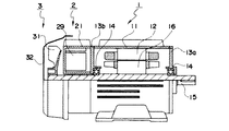
さらに、本発明は、基本的な手段として、図1に示すように、従来の制御装置一体型電動機の制御装置ケース21よりも厚みの薄いユニットケース21a,21b,21cに、コンバータ回路22,専用制御・機能回路24,インバータ回路23の各機能ユニットを分けて内蔵し、これら複数のユニットケース21a,21b,21cを積み重ね、反負荷側エンドブラケット13bと冷却ファン31の間で、反負荷側エンドブラケット13bまたはハウジング11に取り付けることにより構成する。
【0013】
【発明の実施の形態】
以下、本発明の実施例を図面を用いて説明する。
図1を用いて、請求項1に記載された本発明の第1の実施の形態を説明する。図1に示すように、この実施の形態の制御装置一体型電動機は、図8に示した制御装置一体型電動機に比べて、コントローラ部2の制御装置ケース21を複数のユニットケース21a,21b,21cに分割し、それぞれのユニットケース21a,21b,21cに異なる機能を有する装置22,23,24を収容したこと、これらの機能をユーザの要求に従って取捨選択して組み合わせるようにしたことを特徴としている。図1において、図8と同じ符号は同様の構成要素を示している。
【0014】
ユニットケース21a,21b,21cは、それぞれ、同軸に配置された外筒211と内筒212とを中央に穴を有するケース底板213で接続した形状を有し、アルミ等の金属部材により成形されている。ユニットケース21の内筒212には電動機本体1の反負荷側シャフト15が貫通する。
それぞれのユニットケース21a,21b,21cには、コンバータ回路22、専用制御・機能回路24、インバータ回路23がユニットケース21の内側空間に収容され、それぞれの機能回路の回路基板は、ユニットケース21a,21b,21cの内周面や、ケース底板213に取付けられている。ここで、専用制御・機能回路24は、ユーザーの仕様に応じて、例えば電源高調波フィルター等の回路により構成されている。
【0015】
これらユニットケース21a,21b,21cは、積み重ねて反負荷側エンドブラケット13bまたはハウジング11にボルト等により固定される。また、ユニットケース21a,21b,21cを貫通するシャフト15の反負荷側の端に冷却ファン31が取り付けられ、さらに、最外側のユニットケース21aには冷却ファン31を覆うファンカバー32が取り付けられている。
なお、コンバータ回路22と専用制御・機能回路24、専用制御・機能回路24とインバータ回路23、インバータ回路23と固定子12は、それぞれ図示を省略した着脱可能なコネクタ等を介して電気的に接続されている。
【0016】
冷却ファン31により、ユニットケース21a,21b,21cおよびハウジング11の外周に冷却風が流され、ユニットケース内の回路および電動機を冷却する。ここで、制御装置において最も発熱量の大きいスイッチング素子は、ケース21cに内蔵され、周囲温度上昇により寿命が大きく低下するコンバータ回路22の平滑コンデンサは、ケース21aに内蔵されている。
【0017】
各ユニットケース間は、各ユニットケースの底板213により断熱されるので、ユニットケース21aの内部温度は、ケース21c内のスイッチング素子の発熱の影響を受けにくいので比較的低く維持することができ、コンデンサの寿命が極端に低下することがなくなる。このため、制御装置を大容量化することおよび小型化することができる。
【0018】
また、ユニットケース21aに内蔵されるコンバータ回路22と、ユニットケース21cに内蔵されるインバータ回路23は、交流電源から可変周波数電源に変換する必要最小限の基本回路のみを有しているので、ユーザーの要求仕様に応じて専用制御・機能回路24を内蔵したケース21bを追加または交換することによって、ユーザーの要求仕様に容易に、かつ低価格で対応することができる。さらに、制御装置を複数のユニットに分離したので、制御装置が故障したとき、故障した部品・回路を含むユニットケースのみを交換すればよく、修理が短時間で済むとともに、制御装置全部を交換する必要がないことから修理費を低減することができる。
【0019】
図2を用いて、本発明の第2の実施の形態を説明する。図2に示す電動機は、図1に示した電動機の回転子16を永久磁石式回転子18とし、ケース21cに回転子の磁石位置検出器25を内蔵した点に特徴を有している。図2において、図1と同じ符号は同様の構成要素を示している。
このように構成することによって、永久磁石式回転子を有する電動機においても第1の実施の形態と同様の効果を得ることができる。
【0020】
図3を用いて、本発明の第3の実施の形態および第4の実施の形態を説明する。
第3の実施の形態は、コンバータ回路22を内蔵したユニットケース21aとインバータ回路23を内蔵したユニットケース21cを積み重ねて、反負荷側エンドブラケット13b、またはハウジング11にボルト等により取り付けた点に特徴を有している。
このような構成とすることによって、専用制御・機能回路24を省略することができ、制御装置一体型電動機を小型化することができるとともに、安価な電動機とすることができる。
【0021】
また、第4の実施の形態は、回転子16を永久磁石式回転子18とし、ケース21cに回転子の磁石位置検出器25を内蔵したものであり、このような構成とすることによって、永久磁石回転子を有する制御装置一体型電動機において、専用制御・機能回路24を省略することができ、制御装置一体型電動機を小型化することができるとともに、安価な電動機とすることができる。
【0022】
図4を用いて、本発明の第5の実施の形態および第6の実施の形態を説明する。
第5の実施の形態は、コンバータ回路を省略し、専用制御・機能回路24を内蔵したケース21bとインバータ回路23を内蔵したケース21cを積み重ねて、反負荷側エンドブラケット13bまたはハウジング11にボルト等により取り付けた点に特徴を有している。
このように電動機自体のコンバータを省略することによって、図5に示すように、コンバータ22を共用して一台のコンバータで多数の電動機を運転する場合や、交流電源ではなく直流電源を受電し電動機を運転する場合において、電動機自体のコンバータ回路22を省略することができ、制御装置一体型電動機を小型化することができるとともに、安価な電動機とすることができる。
【0023】
第6の実施の態様は、さらに、回転子16を永久磁石式回転子18とするとともに、ユニットケース21cに回転子の磁石位置検出器25を内蔵した点に特徴を有している。これにより、永久磁石式回転子を有する電動機において、図5に示すように、コンバータを共用し、一台のコンバータで多数の電動機を運転する場合や、交流電源ではなく直流電源を受電し電動機を運転する場合において、電動機自体のコンバータ回路22を省略することができ、制御装置一体型電動機を小型化することができるとともに、安価な電動機とすることができる。
【0024】
図6を用いて、本発明の第7の実施の形態および第8の実施の形態ならびに第9の実施の形態を説明する。
第7の実施の形態は、コンバータ回路22を内蔵したユニットケース21aと、専用制御・機能回路24を内蔵したユニットケース21bと、インバータ回路23を内蔵したユニットケース21cを積み重ね、さらに冷却ファン側のユニットにブレーキユニット26を積み重ね、反負荷側エンドブラケット13bまたはハウジング11にボルト等により固定した点に特徴を有している。
このような構成とすることによって、ブレーキの機能を追加させた制御装置一体型電動機を得ることができ、第1の実施の形態と同様の効果を得ることができる。
【0025】
第8の実施の形態は、コンバータ回路22を内蔵したユニットケース21aと、インバータ回路23を内蔵したユニットケース21cを積み重ね、さらに冷却ファン側のユニットにブレーキユニット26を積み重ね、反負荷側エンドブラケット13bまたはハウジング11にボルト等により固定した点に特徴を有している。
このような構成とすることによって、ブレーキの機能を追加させた制御装置一体型電動機を得ることができ、第3の実施の形態と同様の効果を得ることができる。
【0026】
第9の実施の形態は、専用制御・機能回路24を内蔵したユニットケース21bと、インバータ回路23を内蔵したユニットケース21cを積み重ね、さらに冷却ファン側のユニットにブレーキユニット26を積み重ね、反負荷側エンドブラケット13bまたはハウジング11にボルト等により固定した点に特徴を有している。
このような構成とすることによって、ブレーキの機能を追加させた制御装置一体型電動機を得ることができ、第5の実施の形態と同様の効果を得ることができる。
以上、記述したように、本発明の実施の形態によれば、制御装置をコンバータ回路、専用制御・機能回路、インバータ回路に分け、それぞれの回路を各ユニットケースに内蔵し、これらユニットケースを組み合わせて電動機本体に一体化することによって、ユーザーの様々の要求仕様に対して、低コスト化、小型化を計ることができる。また、コンバータの平滑コンデンサをスイッチング素子を有するインバータ素子から遠ざけることができるので、平滑コンデンサの周囲温度上昇を抑えることができ、比較的容量の大きい電動機についても制御装置一体型構造を採用することができる。また、制御装置が故障したときには、故障した部品を含むユニットケースのみ交換すればよいので、容易に修理ができ、かつ従来に比べ修理費および資源の無駄使いを低減することができる。
【0027】
【発明の効果】
以上、記述したように、本発明によれば、電動機と制御装置を一体化することができる。
【図面の簡単な説明】
【図1】本発明にかかる制御装置一体型電動機の第1の実施形態の一部断面側面図。
【図2】本発明にかかる制御装置一体型電動機の第2の実施形態の一部断面側面図。
【図3】本発明にかかる制御装置一体型電動機の第3,第4の実施形態の一部断面側面図。
【図4】本発明にかかる制御装置一体型電動機の第5,第6の実施形態の一部断面側面図。
【図5】図4に示す制御装置一体型電動機のシステムの構成図。
【図6】本発明にかかる制御装置一体型電動機の第7,第8,第9の実施形態の一部断面側面図。
【図7】従来の制御装置一体型電動機のシステム構成図。
【図8】従来の制御装置一体型電動機の第1の実施形態の一部断面側面図。
【符号の説明】
1 電動機
2 コントローラ部
3 冷却部
4 交流電源
11 ハウジング
12 固定子
13a 負荷側エンドブラケット
13b 反負荷側エンドブラケット
14 ベアリング
15 シャフト
16 回転子
18 永久磁石式回転子
21 制御装置ケース
21a コンバータ回路用ユニットケース
21b 専用制御・機能回路用ユニットケース
21c インバータ回路用ユニットケース
21d ブレーキ用ユニットケース
22 コンバータ回路
23 インバータ回路
24 専用制御・機能回路
25 位置検出器
26 ブレーキ
29 制御装置
31 冷却ファン
32 ファンカバー[0001]
BACKGROUND OF THE INVENTION
The present invention relates to electric motive controlled by an inverter or the like.
[0002]
[Prior art]
The structure of a general motor control system composed of an electric motor and a control device will be described with reference to FIG. 7, and the schematic structure of the motor with an integrated control device will be described with reference to FIG.
As shown in FIG. 7, the motor control system includes an AC power source 4, a
[0003]
Conventionally, such an electric motor control system uses the electric motor body 1 and the
Furthermore, there is a problem that a cooling mechanism such as a cooling fan or a heat radiating fin for cooling the separately placed control unit is required, and the size and cost are increased.
[0003]
In order to solve such a problem, it can be considered that the
[0004]
The structure of an electric motor having a general permanent magnet rotor will be described with reference to FIG. FIG. 8 is a side view of the controller-integrated electric motor, and shows the upper half of the electric motor in a sectional view.
As shown in FIG. 8, the control device-integrated electric motor includes a
The
[0005]
Here, the
As a main prior art relating to such an electric motor, there is JP-A-60-152247.
[0006]
On the other hand, in an electric motor having a stator and a bracket molded with resin, a rotor held on a rotating shaft, a ball bearing holding the rotating shaft, and a cooling fan attached to the non-load side of the rotating shaft, Japanese Patent Laid-Open No. Hei 6-292346 discloses a controller-integrated electric motor in which a power circuit and a control circuit are built in a cylindrical case having a hole through which is inserted in the center, and the case is attached to a bracket.
[0007]
[Problems to be solved by the invention]
However, any of the above-described control device-integrated electric motors has the following problems.
In recent years, there has been an increasing demand from users for lowering the price and size of electric motors, and there is also an increased demand for dedicated specifications for control devices according to individual user usage conditions. The number of cases where dedicated circuits are added is increasing.
In order to meet such a demand, if a space for adding a dedicated circuit is provided in the control device case in advance, there is a problem that if the dedicated circuit is unnecessary, it becomes a useless space and cannot be reduced in size. .
In addition, if the control device case is manufactured according to the circuit space that meets each requirement, there is a problem that the number of types of cases increases and the cost increases.
[0008]
Conventionally, when the control device is miniaturized, a temperature rise in a space in which electronic components are arranged has been a problem.
The most heat-generating component in a control device is a switching element such as a power transistor that constitutes an inverter circuit, but such an element is often attached to a case so that heat can be directly dissipated. Their own temperature rise is rarely a problem. However, an electrolytic capacitor such as a smoothing capacitor constituting the converter circuit has a significant decrease in component life due to an increase in ambient temperature.
In order to prevent such a decrease in the component life, it is necessary to suppress the temperature increase around the capacitor, and it is necessary to suppress the temperature increase of the switching element and the like. Therefore, the capacity of the switching elements that can be used is limited, and it has been difficult to adopt a controller-integrated structure for an electric motor having a medium capacity or more.
[0009]
When a component of the control device fails, many (especially small-capacity models) replace the entire control device without repairing the failed part of the control device. This causes a problem that normal functions and parts other than the failed part are discarded, and resources are wasted.
[0010]
Japanese Utility Model Laid-Open No. 63-33391 discloses that the converter, the inverter, and the control device are unitized, but the specific configuration for integrating the motor and the control device is as follows. Not shown.
[0011]
The object of the present invention is to solve these problems, to meet the specifications required by each user, and to reduce the cost and size of the apparatus. An object of the present invention is to provide a control device-integrated electric motor that enables a control device-integrated structure even in an output model and has excellent maintainability.
[0012]
[Means for solving the problems]
In order to solve these problems, the present invention divides the control device into several functional units for each function, stores each functional unit in a separate case, and combines these cases into an integrated motor body. I did it.
Further, as a basic means, the present invention provides a
[0013]
DETAILED DESCRIPTION OF THE INVENTION
Embodiments of the present invention will be described below with reference to the drawings.
A first embodiment of the present invention described in claim 1 will be described with reference to FIG. As shown in FIG. 1, the controller-integrated electric motor of this embodiment has a
[0014]
Each of the
In each
[0015]
These
The
[0016]
The cooling
[0017]
Since each unit case is insulated by the bottom plate 213 of each unit case, the internal temperature of the unit case 21a is hardly affected by the heat generated by the switching element in the
[0018]
In addition, the
[0019]
A second embodiment of the present invention will be described with reference to FIG. The motor shown in FIG. 2 is characterized in that the
By configuring in this way, the same effect as in the first embodiment can be obtained even in an electric motor having a permanent magnet rotor.
[0020]
With reference to FIG. 3, illustrating a third embodiment and a fourth embodiment of the present invention.
The third embodiment is characterized in that a unit case 21a containing a
By adopting such a configuration, the dedicated control /
[0021]
In the fourth embodiment, the
[0022]
With reference to FIG. 4, a description will be given of a fifth embodiment and a sixth embodiment of the present invention.
In the fifth embodiment, a converter circuit is omitted, a
Thus, by omitting the converter of the motor itself, as shown in FIG. 5, when the
[0023]
The sixth embodiment is further characterized in that the
[0024]
With reference to FIG. 6, illustrating a seventh embodiment and eighth ninth embodiment of the embodiment the arrangement of embodiment of the present invention.
In the seventh embodiment, a unit case 21a incorporating a
By adopting such a configuration, it is possible to obtain a control device-integrated electric motor to which a brake function is added, and it is possible to obtain the same effect as that of the first embodiment.
[0025]
In the eighth embodiment, a unit case 21a containing a
By adopting such a configuration, it is possible to obtain a control device-integrated electric motor to which a brake function is added, and it is possible to obtain the same effect as that of the third embodiment.
[0026]
In the ninth embodiment, a
By adopting such a configuration, it is possible to obtain a controller-integrated electric motor to which a brake function is added, and it is possible to obtain the same effect as that of the fifth embodiment.
As described above, according to the embodiment of the present invention, the control device is divided into a converter circuit, a dedicated control / function circuit, and an inverter circuit, each circuit is built in each unit case, and these unit cases are combined. By integrating it into the motor body, it is possible to reduce the cost and size for various user requirements. Further, since the smoothing capacitor of the converter can be kept away from the inverter element having the switching element, an increase in the ambient temperature of the smoothing capacitor can be suppressed, and a controller integrated structure can be adopted even for a motor having a relatively large capacity. it can. Further, when the control device breaks down, it is only necessary to replace the unit case including the failed part. Therefore, repair can be easily performed, and repair costs and waste of resources can be reduced as compared with the conventional case.
[0027]
【The invention's effect】
As heretofore described, according to the present invention, can you to integrate the motor and the control device.
[Brief description of the drawings]
FIG. 1 is a partial cross-sectional side view of a first embodiment of a controller-integrated electric motor according to the present invention.
FIG. 2 is a partial cross-sectional side view of a second embodiment of the controller-integrated electric motor according to the present invention.
FIG. 3 is a partial cross-sectional side view of third and fourth embodiments of a controller-integrated electric motor according to the present invention.
FIG. 4 is a partial cross-sectional side view of fifth and sixth embodiments of a controller-integrated electric motor according to the present invention.
FIG. 5 is a configuration diagram of a system of the controller-integrated electric motor shown in FIG. 4;
FIG. 6 is a partial cross-sectional side view of seventh, eighth, and ninth embodiments of the controller-integrated electric motor according to the present invention.
FIG. 7 is a system configuration diagram of a conventional controller-integrated electric motor.
FIG. 8 is a partial cross-sectional side view of a first embodiment of a conventional controller-integrated electric motor.
[Explanation of symbols]
DESCRIPTION OF SYMBOLS 1
Claims (7)
シャフトが貫通する穴を中央に有するアルミ等の金属部材により形成される円筒状のケースで、インバータ回路を内蔵するケースと、特定の機能を有する制御回路を内蔵したケースと、コンバータ回路を内蔵するケースを、反負荷側エンドブラケットと冷却ファンとの間で軸方向に制御回路を内蔵するケースを間に挟んで多段に積み重ねて反負荷側エンドブラケットまたはハウジングに固定したことを特徴とする制御装置一体型電動機。A housing, a stator having a multiphase AC winding held in the housing, a rotor held by the shaft, a bearing holding the shaft, an end bracket holding the bearing, and an anti-load side end bracket In an electric motor having a cooling fan attached to the end of the fan and a cover covering the cooling fan,
A cylindrical case formed of a metal member such as aluminum with a hole through which the shaft passes in the center. A case with an inverter circuit, a case with a control circuit with a specific function, and a converter circuit. A control device characterized in that the case is stacked in multiple stages with the case containing the control circuit in the axial direction between the anti-load side end bracket and the cooling fan, and is fixed to the anti-load side end bracket or the housing. Integrated motor.
シャフトが貫通する穴を中央に有するアルミ等の金属部材により形成される円筒状のケースで、インバータ回路を内蔵するケースと、コンバータ回路を内蔵するケースを、反負荷側エンドブラケットと冷却ファンとの間で軸方向に2段に積み重ねて反負荷側エンドブラケットまたはハウジングに固定したことを特徴とする制御装置一体型電動機。A housing, a stator having a multiphase AC winding held in the housing, a rotor held by the shaft, a bearing holding the shaft, an end bracket holding the bearing, and an anti-load side end bracket In an electric motor having a cooling fan attached to the end of the fan and a cover covering the cooling fan,
A cylindrical case formed of a metal member such as aluminum with a hole through which the shaft passes in the center. The case that incorporates the inverter circuit and the case that incorporates the converter circuit are connected between the anti-load side end bracket and the cooling fan. A controller-integrated electric motor characterized by being stacked in two stages in the axial direction between and fixed to an anti-load side end bracket or a housing.
シャフトが貫通する穴を中央に有するアルミ等の金属部材により形成される円筒状のケースで、インバータ回路を内蔵するケースと、特定の機能を有する制御回路を内蔵したケースを、反負荷側エンドブラケットと冷却ファンとの間で軸方向に多段に積み重ねて反負荷側エンドブラケットまたはハウジングに固定したことを特徴とする制御装置一体型電動機。A housing, a stator having a multiphase AC winding held in the housing, a rotor held by the shaft, a bearing holding the shaft, an end bracket holding the bearing, and an anti-load side end bracket In an electric motor having a cooling fan attached to the end of the fan and a cover covering the cooling fan,
Cylindrical case formed of a metal member such as aluminum with a hole through which the shaft passes in the center, a case with a built-in inverter circuit, and a case with a control circuit with a specific function The controller-integrated electric motor is characterized in that it is stacked in multiple stages in the axial direction between the fan and the cooling fan and fixed to the anti-load side end bracket or the housing.
シャフトが貫通する穴を中央に有するアルミ等の金属部材により形成される円筒状のケースで、インバータ回路を内蔵するケースと、特定の機能を有する制御回路を内蔵したケースと、コンバータ回路を内蔵するケースと、ブレーキユニットを内蔵するケースを、反負荷側エンドブラケットと冷却ファンとの間で軸方向にブレーキユニットが冷却ファン側に位置するように多段に積み重ねて反負荷側エンドブラケットまたはハウジングに固定することを特徴とする制御装置一体型電動機。A housing, a stator having a multiphase AC winding held in the housing, a rotor held by the shaft, a bearing holding the shaft, an end bracket holding the bearing, and an anti-load side end bracket In an electric motor having a cooling fan attached to the end of the fan and a cover covering the cooling fan,
A cylindrical case formed of a metal member such as aluminum with a hole through which the shaft passes in the center. A case with an inverter circuit, a case with a control circuit with a specific function, and a converter circuit. The case and the case containing the brake unit are stacked in multiple stages so that the brake unit is positioned on the cooling fan side in the axial direction between the anti-load side end bracket and the cooling fan, and fixed to the anti-load side end bracket or housing. A control device-integrated electric motor.
シャフトが貫通する穴を中央に有するアルミ等の金属部材により形成される円筒状のケースで、インバータ回路を内蔵するケースと、コンバータ回路を内蔵するケースと、ブレーキユニットを内臓するケースを、反負荷側エンドブラケットと冷却ファンとの間で軸方向にブレーキユニットが冷却ファン側に位置するように多段に積み重ねて反負荷側エンドブラケットまたはハウジングに固定することを特徴とする制御装置一体型電動機。 A housing, a stator having a multiphase AC winding held in the housing, a rotor held by the shaft, a bearing holding the shaft, an end bracket holding the bearing, and an anti-load side end bracket In an electric motor having a cooling fan attached to the end of the fan and a cover covering the cooling fan,
A cylindrical case formed of a metal member such as aluminum with a hole through which the shaft passes in the center. A case with an inverter circuit, a case with a converter circuit, and a case with a built-in brake unit A controller-integrated electric motor characterized by being stacked in multiple stages so that the brake units are positioned on the cooling fan side in the axial direction between the side end bracket and the cooling fan and fixed to the non-load side end bracket or the housing .
シャフトが貫通する穴を中央に有するアルミ等の金属部材により形成される円筒状のケースで、インバータ回路を内蔵するケースと、特定の機能を有する制御回路を内蔵したケースと、ブレーキユニットを内蔵するケースを、反負荷側エンドブラケットと冷却ファンとの間で軸方向にブレーキユニットが冷却ファン側に位置するように多段に積み重ねて反負荷側エンドブラケットまたはハウジングに固定することを特徴とする制御装置一体型電動機。A housing, a stator having a multiphase AC winding held in the housing, a rotor held by the shaft, a bearing holding the shaft, an end bracket holding the bearing, and an anti-load side end bracket In an electric motor having a cooling fan attached to the end of the fan and a cover covering the cooling fan,
A cylindrical case formed by a metal member such as aluminum having a bore in which the shaft penetrates the center, built a case that incorporates the inverter circuit, and a case with a built-in control circuit having a specific function, the brake unit The control is characterized in that the case is stacked in multiple stages so that the brake unit is positioned on the cooling fan side in the axial direction between the anti-load side end bracket and the cooling fan and fixed to the anti-load side end bracket or the housing. Device-integrated electric motor.
Priority Applications (1)
| Application Number | Priority Date | Filing Date | Title |
|---|---|---|---|
| JP17814797A JP3688853B2 (en) | 1997-07-03 | 1997-07-03 | Control device integrated motor |
Applications Claiming Priority (1)
| Application Number | Priority Date | Filing Date | Title |
|---|---|---|---|
| JP17814797A JP3688853B2 (en) | 1997-07-03 | 1997-07-03 | Control device integrated motor |
Publications (2)
| Publication Number | Publication Date |
|---|---|
| JPH1127903A JPH1127903A (en) | 1999-01-29 |
| JP3688853B2 true JP3688853B2 (en) | 2005-08-31 |
Family
ID=16043468
Family Applications (1)
| Application Number | Title | Priority Date | Filing Date |
|---|---|---|---|
| JP17814797A Expired - Lifetime JP3688853B2 (en) | 1997-07-03 | 1997-07-03 | Control device integrated motor |
Country Status (1)
| Country | Link |
|---|---|
| JP (1) | JP3688853B2 (en) |
Cited By (1)
| Publication number | Priority date | Publication date | Assignee | Title |
|---|---|---|---|---|
| CN103904813A (en) * | 2012-12-25 | 2014-07-02 | 中山大洋电机股份有限公司 | Large-power motor heat-radiation structure |
Families Citing this family (22)
| Publication number | Priority date | Publication date | Assignee | Title |
|---|---|---|---|---|
| DE19957064B4 (en) * | 1999-11-26 | 2020-06-18 | Sew-Eurodrive Gmbh & Co Kg | cover |
| JP4597312B2 (en) * | 2000-05-12 | 2010-12-15 | 住友重機械工業株式会社 | Control motor and speed control device mounting structure for control motor |
| DE10242414A1 (en) * | 2002-09-12 | 2004-03-25 | Hilti Ag | Power tool with blower |
| AU2004307193B2 (en) * | 2003-10-30 | 2009-03-12 | Regal Beloit Australia Pty Ltd | Variable speed electric motors |
| AU2003259599A1 (en) * | 2003-10-30 | 2005-05-19 | Cmg Technology Pty Ltd | Variable speed electric motors |
| JP4156542B2 (en) * | 2004-03-03 | 2008-09-24 | 三菱電機株式会社 | Rotating electrical machine for vehicle |
| JP2005304199A (en) | 2004-04-13 | 2005-10-27 | Mitsubishi Electric Corp | Vehicle dynamo-electric machine apparatus |
| JP2007037280A (en) * | 2005-07-27 | 2007-02-08 | Mitsubishi Electric Corp | Rotary electric machine with integrated inverter |
| JP2007060734A (en) | 2005-08-22 | 2007-03-08 | Mitsubishi Electric Corp | Rotary electric machine |
| DE102005058400A1 (en) * | 2005-11-30 | 2007-05-31 | Jungheinrich Ag | Driving and steering system for wheel of industrial truck, has electronic control unit, which consists of printed circuit board, arranged coaxially between traction motor and steering motor or steering motor and steering gear |
| DE102006047269A1 (en) * | 2006-10-04 | 2008-04-10 | Robert Bosch Gmbh | converter motor |
| DE102007008229B4 (en) | 2007-02-20 | 2021-09-23 | Mitsubishi Electric Corp. | Rotating electric machine |
| DE102007010357A1 (en) | 2007-03-03 | 2008-09-04 | Jungheinrich Aktiengesellschaft | Drive unit, particularly for industrial trucks, has electric motor and control section arranged in common housing and separate cooling channel with highly effective thermal conductor |
| JP5238348B2 (en) * | 2008-05-16 | 2013-07-17 | 株式会社荏原製作所 | Motor assembly and pump device |
| JP4628460B2 (en) | 2008-10-22 | 2011-02-09 | 三菱電機株式会社 | Rotating electric machine and manufacturing method thereof |
| JP2011234513A (en) * | 2010-04-28 | 2011-11-17 | Mitsubishi Electric Corp | Control unit-integrated rotary electric machine |
| JP5722644B2 (en) | 2011-01-27 | 2015-05-27 | 株式会社日立産機システム | Rotating electric machine |
| JP5783830B2 (en) | 2011-07-22 | 2015-09-24 | 株式会社日立産機システム | Rotating electric machine |
| MX2018011010A (en) | 2016-03-11 | 2019-03-07 | Itt Mfg Enterprises Llc | Motor assembly for driving a pump or rotary device, having power plane with multi-layer power and control printed circuit board assembly. |
| JP6302023B2 (en) * | 2016-09-07 | 2018-03-28 | 株式会社日立産機システム | Rotating electric machine |
| JP6871749B2 (en) * | 2017-02-07 | 2021-05-12 | 株式会社荏原製作所 | Motor assembly |
| WO2019151186A1 (en) * | 2018-02-01 | 2019-08-08 | 株式会社荏原製作所 | Electric motor assembly |
-
1997
- 1997-07-03 JP JP17814797A patent/JP3688853B2/en not_active Expired - Lifetime
Cited By (2)
| Publication number | Priority date | Publication date | Assignee | Title |
|---|---|---|---|---|
| CN103904813A (en) * | 2012-12-25 | 2014-07-02 | 中山大洋电机股份有限公司 | Large-power motor heat-radiation structure |
| CN103904813B (en) * | 2012-12-25 | 2016-05-04 | 中山大洋电机股份有限公司 | A kind of heavy-duty motor radiator structure |
Also Published As
| Publication number | Publication date |
|---|---|
| JPH1127903A (en) | 1999-01-29 |
Similar Documents
| Publication | Publication Date | Title |
|---|---|---|
| JP3688853B2 (en) | Control device integrated motor | |
| KR100783253B1 (en) | Rotating electric machine with built-in control device | |
| CN101005224B (en) | Control device integrated dynamo-electric machine | |
| JP3958593B2 (en) | Vehicle power supply | |
| KR100770103B1 (en) | Rotary electric machine for vehicles | |
| EP2354550B1 (en) | Integrated-inverter electric compressor | |
| JP4275614B2 (en) | Rotating electric machine for vehicles | |
| US20030173839A1 (en) | Liquid-cooled rotary electric machine integrated with an inverter | |
| JP6621491B2 (en) | Rotating electric machine | |
| WO2014087729A1 (en) | Inverter-integrated electric compressor | |
| JP2004112860A (en) | Alternator for vehicle | |
| JP2012157194A (en) | Rotary electric machine assembly | |
| US20030094920A1 (en) | Inverter-equipped motor | |
| US20100090554A1 (en) | Outer-rotor brushless motor | |
| US6208052B1 (en) | Cooling module for an electronically controlled engine | |
| JP4879772B2 (en) | Electrical equipment | |
| JP4889517B2 (en) | Rotating electrical machine equipment | |
| JP6302023B2 (en) | Rotating electric machine | |
| JP2003274599A (en) | Driving device | |
| JP2005151712A (en) | Power supply system | |
| JPH09285056A (en) | Motor | |
| JP6854936B1 (en) | Rotating machine | |
| JP6365654B2 (en) | Rotating electric machine | |
| JP6961990B2 (en) | Motor unit | |
| JP2007166900A (en) | Power unit for vehicle |
Legal Events
| Date | Code | Title | Description |
|---|---|---|---|
| A521 | Written amendment |
Free format text: JAPANESE INTERMEDIATE CODE: A523 Effective date: 20040628 |
|
| A621 | Written request for application examination |
Free format text: JAPANESE INTERMEDIATE CODE: A621 Effective date: 20040628 |
|
| A711 | Notification of change in applicant |
Free format text: JAPANESE INTERMEDIATE CODE: A712 Effective date: 20040628 |
|
| RD02 | Notification of acceptance of power of attorney |
Free format text: JAPANESE INTERMEDIATE CODE: A7422 Effective date: 20040628 |
|
| A521 | Written amendment |
Free format text: JAPANESE INTERMEDIATE CODE: A821 Effective date: 20040628 |
|
| A977 | Report on retrieval |
Free format text: JAPANESE INTERMEDIATE CODE: A971007 Effective date: 20050228 |
|
| A131 | Notification of reasons for refusal |
Free format text: JAPANESE INTERMEDIATE CODE: A131 Effective date: 20050308 |
|
| A521 | Written amendment |
Free format text: JAPANESE INTERMEDIATE CODE: A523 Effective date: 20050506 |
|
| TRDD | Decision of grant or rejection written | ||
| A01 | Written decision to grant a patent or to grant a registration (utility model) |
Free format text: JAPANESE INTERMEDIATE CODE: A01 Effective date: 20050607 |
|
| A61 | First payment of annual fees (during grant procedure) |
Free format text: JAPANESE INTERMEDIATE CODE: A61 Effective date: 20050609 |
|
| R150 | Certificate of patent or registration of utility model |
Free format text: JAPANESE INTERMEDIATE CODE: R150 |
|
| FPAY | Renewal fee payment (event date is renewal date of database) |
Free format text: PAYMENT UNTIL: 20080617 Year of fee payment: 3 |
|
| FPAY | Renewal fee payment (event date is renewal date of database) |
Free format text: PAYMENT UNTIL: 20090617 Year of fee payment: 4 |
|
| FPAY | Renewal fee payment (event date is renewal date of database) |
Free format text: PAYMENT UNTIL: 20100617 Year of fee payment: 5 |
|
| FPAY | Renewal fee payment (event date is renewal date of database) |
Free format text: PAYMENT UNTIL: 20110617 Year of fee payment: 6 |
|
| FPAY | Renewal fee payment (event date is renewal date of database) |
Free format text: PAYMENT UNTIL: 20110617 Year of fee payment: 6 |
|
| FPAY | Renewal fee payment (event date is renewal date of database) |
Free format text: PAYMENT UNTIL: 20120617 Year of fee payment: 7 |
|
| FPAY | Renewal fee payment (event date is renewal date of database) |
Free format text: PAYMENT UNTIL: 20120617 Year of fee payment: 7 |
|
| FPAY | Renewal fee payment (event date is renewal date of database) |
Free format text: PAYMENT UNTIL: 20130617 Year of fee payment: 8 |
|
| EXPY | Cancellation because of completion of term |