JP3688198B2 - Rotary encoder - Google Patents
Rotary encoder Download PDFInfo
- Publication number
- JP3688198B2 JP3688198B2 JP2000401370A JP2000401370A JP3688198B2 JP 3688198 B2 JP3688198 B2 JP 3688198B2 JP 2000401370 A JP2000401370 A JP 2000401370A JP 2000401370 A JP2000401370 A JP 2000401370A JP 3688198 B2 JP3688198 B2 JP 3688198B2
- Authority
- JP
- Japan
- Prior art keywords
- rotating body
- rotary encoder
- speed nut
- shaft portion
- tongue piece
- Prior art date
- Legal status (The legal status is an assumption and is not a legal conclusion. Google has not performed a legal analysis and makes no representation as to the accuracy of the status listed.)
- Expired - Fee Related
Links
Images


Landscapes
- Measurement Of Length, Angles, Or The Like Using Electric Or Magnetic Means (AREA)
- Transmission And Conversion Of Sensor Element Output (AREA)
- Power Steering Mechanism (AREA)
Description
【0001】
【発明の属する技術分野】
本発明は、自動車のパワーステアリング等において、ステアリングの回転角度を検出する等の用途に用いられる回転型エンコーダであって、特にその内部の取付構造に関する。
【0002】
【従来の技術】
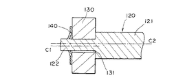
従来の回転型エンコーダR1を図9〜図11に基づいて説明すると、図9は従来の回転型エンコーダの要部断面図、図10はそのスピードナットの平面図、図11は従来の回転型エンコーダの要部拡大断面図である。
【0003】
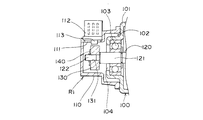
回転型エンコーダR1が取り付けられる本体部100には、一部の壁部101から有底円筒状に突出して形成された円筒部102が形成されており、該円筒部102内には複数のボールを有するボールベアリング部からなる軸受部103が配置されている。
また、円筒部102の側壁の中央には、円状の通孔104が形成されている。
【0004】
回転型エンコーダR1は、2段の筒状部からなる筐体110と、軸部120と、該軸部120と共回りするコード部材たるコード板130と、このコード板130に対向して配置されたホール素子113と、該コード板130が軸部120から抜け落ちないように保持するスピードナット140等から構成されている。
【0005】
筐体110は、断面略凸型に形成され、側壁(図9中上方)に開口部111が形成されて、筒状部の開放側が半田付け等の適宜手段によって本体部100に固定されている。また、開口部111には、平板矩形状のプリント基板112が外方に突出するように取り付けられており、該プリント基板112にはホール素子113が検出回路(図示せず)等に接続された状態で取り付けられ、このホール素子113は、開口部111に位置するようになっている。
【0006】
軸部120は、径の大きい第1の軸部121と、該第1の軸部121の一端から突出するように形成されると共に、径の小さい第2の軸部122とから構成されている。そして第1の軸部121は、円筒部102の通孔104を貫通した状態で軸受部103に回転可能に保持されており、また第2の軸部122は、円筒部102から突出して、筐体110の内部に位置している。
【0007】
コード板130は、円板状の永久磁石からなり、中央には貫通孔131が形成されている。そしてこのコード板130の貫通孔131には、第2の軸部122が遊嵌状態で挿通しており、このコード板130の一面が、第1、第2の軸部121、122の境目に位置した段部である第1の軸部121の先端面に当接している。
【0008】
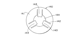
スピードナット140は、金属製の円形平板から構成され、図10に示すように、円板状の基体141と、両側に切り欠き142を設けて基体141から、中央に突出して形成された3つの舌片143と、基体141の中央に形成された円形状の貫通孔144を有している。このような構成をしたスピードナット140は、第2の軸122に強嵌合されて、コード板130の他面に押しつけられて、軸部120からコード板130が抜けるのを防止している。即ち、貫通孔144に第2の軸部122を挿通し、基体141を第1の軸部121方向へ押圧し、スピードナット140と第1の軸部121とでコード板130を挟みつけるようになっている。このとき、3つの舌片143が押圧方向と反対方向(図9中左方)にそれぞれ撓むことによって第2の軸部122に強嵌合する。こうして舌片143が強嵌合すると、スピードナット140は軸線方向へ移動が不可能となり、結果としてコード板130の抜けが防止されると共に、スピードナット140とコード板130が軸部120と共回りするようになる。
【0009】
このとき、第2の軸部122は、コード板130の貫通孔131に遊嵌状態となっているため、図11に示すように、貫通孔131のセンターC1と第2の軸部122のセンターC2とが、軸線方向と直交する方向においてずれたままスピードナット140により、第2の軸部122とコード板130との位置が決定してしまう。
【0010】
次に従来の回転型エンコーダR1の動作を説明すると、ステアリングシャフト(図示せず)を介して軸部120が回転すると、その回転に伴ってコード板130が回転する。そして、ホール素子113により磁極の変化を検出し、プリント基板112に形成されている磁気検出回路(図示せず)によって、コード板130の回転に応じた検出パルスを検出させるようになっている。そして、貫通孔131のセンターC1と第2の軸部122のセンターC2とがずれたまま軸部120が回転すると、コード板130が楕円を描いて回転してしまい、正常なパルスが検出できなくなり、また、その値は回転型エンコーダR1毎に異なる値となってしまうので、精度良く回転角度を測定できないという恐れがある。
【0011】
【発明が解決しようとする課題】
上記説明した従来の回転型エンコーダR1において、スピードナット140は、第2の軸部122に嵌合して、単に、コード板130に当接するのみであるため、スピードナット140とコード板130との位置がずれる恐れがある。このようにスピードナット140とコード板130との間にズレが生ずると、スピードナット140とコード板130のセンター位置C1、C2が決まらず、軸部120を回転させると、コード板130が楕円を描くように回転しまい、このため性能が悪化する。このズレを防止するため、コード板130の貫通孔131と第2の軸部122との精度を手作業で補正しようとすると、量産性が悪化する他、コスト高になるという問題がある。また、両者の寸法精度を高めるとコスト高になってしまうという問題もある。
【0012】
本発明はかかる課題に鑑みてなされたものであり、スピードナットの位置を規制して、軸部の回転に伴ってコード部材が正確な円を描くように回転する回転型エンコーダを提供することを目的とする。
【0013】
【課題を解決するための手段】
上記課題を解決するための第1の解決手段として、本発明の回転型エンコーダは、筐体と、この筐体側に取り付けられた検出素子と、軸部が挿通される取付孔を中心部に備え、前記検出素子に対向するコード部材が設けられ、回転可能に前記筐体に保持された回転体と、複数の舌片を備え、該舌片が前記軸部の外周囲に強嵌合可能なスピードナットとを有し、前記スピードナットは、前記軸部及び前記回転体と共回り可能となっていると共に、前記回転体の回転軸線と直交する方向への前記回転体と前記スピードナットとの間における移動が規制される位置規制手段が設けられた構成とした。
【0014】
また第2の解決手段として、本発明の回転型エンコーダにおける前記スピードナットには係合部が設けられ、該係合部が前記回転体の外周に係止することで、前記位置規制手段が構成されている。
また第3の解決手段として、本発明の回転型エンコーダにおける前記係合部は、筒部で形成されている構成とした。
【0015】
また第4の解決手段として、本発明の回転型エンコーダにおける前記回転体は、前記コード部材を保持する基部と、この基部の外径よりも小さい外径を有し前記基部の端面から前記回転体の回転軸線方向に突出形成された係止部とを備え、該係止部は、円筒もしくは同一円周上に配置された複数の突起から構成され、前記係合部が前記係止部に係止されている構成とした。
【0016】
また第5の解決手段として、本発明の回転型エンコーダにおける前記スピードナットの前記舌片及び前記係合部は、一枚の金属板よって形成されている構成とした。
また第6の解決手段として、本発明の回転型エンコーダにおける前記回転体はカシメ部を有し、該カシメ部に前記スピードナットがカシメ付けられることで、前記位置規制手段が構成されている。
【0017】
また第7の解決手段として、本発明の回転型エンコーダにおける前記スピードナットの複数の前記舌片は、互いに対向して形成されている構成とした。
また第8の解決手段として、本発明の回転型エンコーダにおける前記スピードナットの複数の前記舌片は、第1の舌片と、該第1の舌片と切り欠きを隔てて隣接すると共にこの第1の舌片よりも長さの小さい第2の舌片とを有し、該第2の舌片の先端を結んで形成された円周領域が、前記軸部の外径と略同一である構成とした。
【0018】
また第9の解決手段として、本発明の回転型エンコーダにおける前記スピードナットが係止された側の反対側に位置した前記回転体の面には、前記軸部に形成される鍔部が当接可能としている構成とした。
【0019】
【発明の実施の形態】
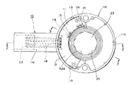
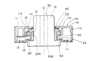
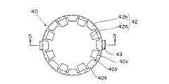
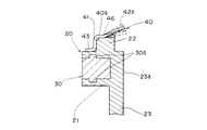
本発明の第1の実施の形態に係る回転型エンコーダを図面を用いて詳細に説明する。図1は本発明の第1の実施の形態の回転型エンコーダに係り軸部や下蓋等を取り除いた下面図、図2は図1の2−2線における断面図、図3は図1の3−3線における断面図、図4は本発明の回転型エンコーダに係るスピードナットの平面図、図5は図4の5−5線における断面図、図6は本発明の回転型エンコーダに係る回転体とスピードナットの取付構造を説明するための要部拡大断面図である。
【0020】
筐体10は、合成樹脂の成型品からなり、基体11と、この基体11とスナップ結合するリング状の平板からなる下蓋12とから構成されている。
基体11は、断面コ字状のリング状の壁部を有する筒状の収納部11aと、該収納部11aの側縁から連結して外方に突出した細長矩形状のコネクタ部11bで構成されている。収納部11aは、大径からなる外側壁11cと、小径からなる内側壁11dと、この外側壁11cと内側壁11dとを連結し、中央部に孔11mを有する平板状の壁部11eとで構成されている。内側壁11dは、図1を参照するに、2箇所外側壁11c側にへこんで凹状部11kを形成している。また、コネクタ部11bには、2段状の矩形状の窪みからなる受部11fが、収納部11aに向かって形成されている。なお、収納部11aとコネクタ部11bとの境目には、コネクタ部11b側に広がるように形成された段部11gが設けられており、外側壁11cの縁部には爪受孔11hが設けられている。
下蓋12は、合成樹脂のリング状の平板から構成され、孔12bを有する中央部がリング状に凹んでいると共に、外縁には爪部を有する取付脚12aが形成されている。
そして、この下蓋12は、収納部11aの開放側を覆うようにスナップ結合されて固定される。即ち、収納部11aの開放側から外側壁11cの内側にはまるように下蓋12を被せ、取付脚12aの爪部が爪受孔11hに係合することで、スナップ結合がなされる。
そして、下蓋12がスナップ結合されると、下蓋12と収納部11aの内・外側壁11d、11cとの間でドーナツ状の中空部11iが形成されると共に、内側壁11dの内側と下蓋12とで収納用の窪み部11jが形成され、この窪み部11jはその上・下が孔11m、12bによって開放された状態となっている。
【0021】
プリント基板13は、扇状で平板状のリジッドな絶縁基板からなり、またコネクタ部11bは、90度折り曲がった4本の端子14を有している。端子14の一端は、プリント基板13を貫通した状態で半田付けされると共に、他端は受部11f内に突出している。また、図1,3に示すように、プリント基板13の内方部には楕円柱状の検出素子たるホール素子15が半田付け等の適宜手段によって、該プリント基板13に対して垂直に取り付けられている。
そして、プリント基板13は、内側壁11d上と段部11g上に載置されると共に、コネクタ部11bに埋設された4本の端子14が半田付けされ、収納部11aの中空部11i内に固定されている。なお、ホール素子15は、図1、3に示すように、内側壁11dの凹状部11k内に収納されて、窪み部11j側に露出している。
【0022】
回転体20は、リング状の基部21と、該基部21の端面から回転軸線G方向に一体にリング状に形成された係止部22と、基部21の中心部に設けられた円筒状の円筒部23とから構成されている。また、基部21の内側に設けられた円筒部23には取付孔23aが形成されいると共に、この円筒部23の端部には、すり鉢状にテーパーが設けてある。
係止部22は、比較的高さの低い円筒から構成され、該円筒の外径は基部21の外径よりも小さくなっている。なお、本実施の形態では係止部22は円筒から構成したものとしたが、同一円周上に形成された複数の突起、例えば比較的大きい角度を有する円弧状に突出した2個の突起や、3個以上の突起を同一間隔に配置しても良い。
【0023】
コード部材30は、プラスチックマグネット等の永久磁石からなり、略リング状を呈し、該コード部材30の上面と下面とにリング状の凸部30aが形成されている。このようなコード部材30は、回転体20にインサート形成により取り付けられて、該回転体20と一体になっている。このとき、コード部材30は凸部30aでも係止されるようになるので、高速で回転して大きな遠心力が加わってもコード部材30を確実に回転体20に保持できるそ、また、コード部材30と回転体20の剥がれを防止することができる。
【0024】
このようにコード部材30と一体となっている回転体20は、筐体10の窪み部11jに収納されて、内側壁11dと対向するようになっている。このとき、コード部材30がホール素子15と同じ高さになるように回転体20を位置させ、コード部材30の一部は、図3に示すように、凹状部11kに収納されたホール素子15に対向する状態となる。
このような状態で収納されたコード部材30と一体になった回転体20は、窪み部11j内を回転自在となっており、回転体20と共回りするコード部材30の磁極の変化をホール素子15が読みとるようになっている。
【0025】
スピードナット40は、特に図4、図5に示すように、一枚の金属板から形成されており、平板のリング状からなる基部40aと、この基部40aの外周縁から下方に延びた筒部からなる係合部41と、基部40aの内周縁から切り起こされて上方に突出形成された複数の第1の舌片42aと、この第1の舌片42a間に位置した状態で基部40aから中心方向に延びる複数の第2の舌片42bと、係合部41の端部外周から互いに反対方向に突出する2つの突出片43有する。第1の舌片42aは、第2の舌片42bよりもラジアル方向の長さが大きく、また第2の舌片42bは、第1の舌片42aと切り欠き40bを隔てて隣接するとと共に、第1の舌片42aよりも長さが短く、この第1、第2の舌片42a、42bは交互に360度に渡って形成されている。第1の舌片42aは、それぞれ基部40aの中心を挟んで互いに対向、即ち中心に向かって互いに向き合っている状態になっていおり、また、第2の舌片42bも同様に基部40aの中心を挟んで互いに向き合って配置されている。また、基部40aの外周には筒部からある係合部41が設けられているため、基部40aは強度が高められ、その結果、第1、第2の舌片42a、42bの両側に設けられた切り欠き40bは、係合部41に近い位置まで深く形成でき、第1の舌片42aの長さを大きくできると共に、基部40aの外径を小さくできて、スピードナット40の小型化を図ることができる。このような第1の舌片42aの伸長化に伴って、第1の舌片42aのバネ強度が低下するが、第1の舌片42aの根本部40cの近傍には、筒部からなる係合部41が設けられているため、基部40aの浮き上がりが防止され、結果としてバネ強度の低下が抑制される。また、第2の舌片42bの先端を結ぶ線で、円周領域を形成している。
なお、本実施の形態では係合部41として筒部を設けたが、必ずしも円筒にする必要はなく、この筒部に代えて比較的大きい角度を有する円弧状の側壁を2個設けたり、3個以上の側壁を同一円周上に設けても良い。そして、このスピードナット40は、一枚の金属板をプレス加工にて打ち抜いて外形を形成し、絞り加工することで、筒部からなる係合部41を形成して製造される。
【0026】
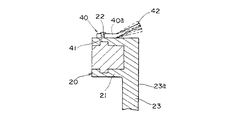
このような構成を有するスピードナット40は、図6に示すように、係合部41が回転体20の係止部22の外周に係止することによって、回転体20と一体になる。即ち、係合部41が係止部22に強嵌合されることによって、スピードナット40は係止部22に確実に固定される。そして、このように係止がなされることで、スピードナット40は、回転体20との間において回転体20の回転軸線Gと直交する方向への移動が規制される。つまり、この係合部41と係止部22との係合によって位置規制手段が構成されている。
【0027】
軸部50は、金属製からなり、本実施の形態では焼結金属によって形成され、円柱状の基部51と、この基部51と一体に形成された円板状をなすフランジからなる鍔部52を有し、中心には基体51から鍔部52にかけて上下に貫通する貫通孔50aが形成されている。
このような軸部50は、回転体20の取付孔23aに挿通され、スピードナット40の第1の舌片42aが撓むことによって該第1の舌片42aと強嵌合状態となる。即ち、軸部50を取付孔23aに挿通し、スピードナット40まで達すると、第2の舌片42bはその先端を結んで形成された円周領域が、軸部50の基部51の外形と略同一で、少なくとも大径になるよう形成してあるので軸中心の位置決めとして機能し、さらに軸部50を押し込むことによって、第1の舌片42aが挿通方向に(図2中上方)に撓んで、軸部50の該外周壁と強嵌合する。そして、鍔部52に回転体20の下端面が当接するまで押圧される。このとき、第1の舌片42aが互いに対向する状態になっており、付勢力が均等に作用するので、スピードナット40に対して軸部50のセンターが決まりやすい。また、鍔部52に回転体20の下端が当接しているので、回転軸線Gに対して回転体20の傾きを抑えることができる。さらには、突出片43が回転体20の図示しない凹部に係合されて、より確実に共回りするようになっている。
【0028】
ところで、軸部50は焼結金属からなっているので十分な強度があり、比較的安価に製造可能であるが、寸法にばらつきが生じやすく、回転体20との隙間が大きい場合、小さい場合等あり、回転体20の取付孔23aとの間にズレが生ずる恐れがあるる。しかし、回転体20の回転軸線Gと直交する方向において、回転体20に対するスピードナット40の移動が、係合部41による係止により規制されているので、たとえ、軸部50と取付孔23aとの間にズレが生じた状態で、軸部50が挿入されても、軸部50が第1の舌片42aに嵌合したとき、軸部50は第1の舌片42aが均等に撓むので、スピードナット40の中心位置となると共に、位置規制手段によって回転体20がスピードナット40に追従するため、回転体20の取付孔23aの中心に軸部50が位置するようになる。即ち、スピードナット40と回転体20との間に形成された位置規制手段によって、軸部50は自動的に取付孔23aの中心に位置するようになる。また、軸部50は第2の舌片42bにガイドされて挿通されるので、回転体20のセンターと軸部50のセンターずれをなくすことができる。
そして、図示していないが、軸部50は貫通孔50aにステアリングシャフトに繋がるウォームギヤ等のシャフトが嵌合され、該シャフトによって回転可能に固定されている。なお、軸部50の圧入時に係合部41と係止部22の嵌合が外れないよう、係合部41と係止部22の嵌合には十分な嵌合力が得られるように設定されている。
【0029】
次に本発明の回転型エンコーダの動作について図2に基づいて説明する。図示せぬステアリングシャフトが回転することによってウォームギアが回転すると、この回転に伴って軸部50が回転する。軸部50が回転すると、回転体20が共回りし、コード部材30も共回りする。そして、2個のホール素子15により磁極の変化を検出して2相の正弦波を出力し、プリント基板13に形成されているCPU等(図示せず)によって、コード部材30の回転に応じた検出パルスを検出し、端子14から電気信号として出力するようになっている。
【0030】
次に本発明の回転型エンコーダの第2の実施の形態について図7に基づいて説明する。図7は本発明の第2の実施の形態の回転型エンコーダに係る回転体とスピードナットの取付構造を説明するための要部拡大断面図である。第2の実施の形態にかかる回転型エンコーダについての説明において、第1の実施の形態と同様の機能を有する部品については、同じ番号・名称を用いる。
【0031】
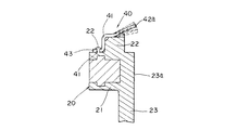
本発明の第2の実施の形態に係る回転型エンコーダは、第1の実施の形態が位置規制手段を回転体20の円筒状の係止部22と、スピードナット40の筒部からなる係合部41による係止によって構成したことに対して、位置規制手段が回転体20に設けた複数個のカシメ部からなる係止部22と、スピードナット40の基部40aに設けられた複数個のカシメ孔からなる係合部41によって、スピードナット40をカシメ付けてすることで構成されたことが異なる。
このようにカシメ付けを行うことにより、スピードナット40は回転軸線Gに直交する方向への移動が、係止部22によって規制される。さらに、カシメ付けにより、基部40aが回転体20の端部に強固に当接するので、第1の舌片42が撓んでも、基部40aが浮く可能性が少なく、且つ回転体20とスピードナット40の分離もなくなる。
【0032】
なお、その他の構成・関係については第1の実施の形態と同様なので、同一部材に同一番号を付し、ここでは説明を省略する。
【0033】
次に本発明の回転型エンコーダの第3の実施の形態について図8に基づいて説明する。図8は本発明の第3の実施の形態の回転型エンコーダに係る回転体とスピードナットの取付構造を説明するための要部拡大断面図である。第3の実施の形態にかかる回転型エンコーダについての説明において、第1、第2の実施の形態と同様の機能を有する部品については、同じ番号・名称を用いる。
【0034】
本発明の第3の実施の形態に係る回転型エンコーダは、第1の実施の形態と第2の実施の形態とを組み合わせた形態から構成されている。すなわち、位置規制手段が、スピードナット40の筒部たる係合部41による係止と、カシメ孔たる係合部41によるカシメ付けとの2つで構成されている。
こうすることで、スピードナット40の回転軸線Gに直交する方向への移動が、リング状の係止部22と筒部たる係合部41及び、突起状のカシメ部たる係止部22とカシメ孔たる係合部41によって、規制される。さらに、カシメ付けにより、突出片43が回転体20の端部に強固に取り付けられるので、スピードナット40が浮く可能性がほとんどない。
【0035】
なお、その他の構成・関係については第1の実施の形態と同様なので、同一部材に同一番号を付し、ここでは説明を省略する。
【0036】
本発明の回転型エンコーダは、上記のような構成を有するが、このような構成に限られないのは言うまでもなく、第1の実施の形態において回転体20の基部21の外周部を係止部22とし、スピードナット40の筒部たる係合部41を回転体20の基部21の外周部に係合しても良い。また、第1、もしくは第3の実施の形態において係止部22は必ずしも円状である必要はなく、多角形状でも良い。このときは、スピードナット40の筒部たる係合部41の形状もこの形状に対応して、多角形状にても良い
。なお、第1〜第3の実施の形態において、軸部50は、実施の形態では焼結金属からなると説明したが、金属の削り出しから構成しても良いのは勿論である。また、コード部材30は円形のリング状をなしているが、八角形等の多角形としても良い。
また、第1〜第3の実施の形態では磁気式の回転型エンコーダについて説明したが磁気式に限らず、光学式にも本発明は適用可能であることは勿論である。
【0037】
【発明の効果】
本発明の回転型エンコーダにおけるスピードナットは、軸部及び回転体と共回り可能となっていると共に、回転体の回転軸線と直交する方向への回転体とスピードナット間における移動が規制される位置規制手段が設けられた構成としたため、回転体に対するスピードナットの位置が規制されるので、仮に軸部とコード部材との間に寸法上のばらつきがあっても、軸部がスピードナットの中心にくると共に、回転体は軸部に強嵌合されるスピードナットに追従して移動し、軸部のセンターが取付孔の中心に位置するので、軸部の回転に伴ってコード部材が正確な円を描くように回転し、所望の出力をだす高性能な回転型エンコーダを提供することができる。
【0038】
また、本発明の回転型エンコーダにおけるスピードナットには係合部が設けられ、該係合部が回転体の外周に係止することで、前記位置規制手段が構成されているので、外周への係合という簡単な構成で、位置規制手段を実現することができる。
【0039】
また、本発明の回転型エンコーダにおける係合部は、筒部で形成されている構成としたため、簡単な構成で係合が確実となり、信頼性の高い回転型エンコーダを提供することができる。また、舌片の根本部を筒部に極力近づけることができ、従って、舌片の長さを大きくできると共に、小型の回転型エンコーダを提供することができる。
【0040】
また、本発明の回転型エンコーダにおける回転体は基部と、この基部の外径よりも小さい外径を有する係止部を備え、係合部が係止部に係止されている構成としたため、係止部がラジアル方向において更に小さくなるので、結果として小型の回転型エンコーダを提供することができる。
【0041】
また、本発明の回転型エンコーダにおけるスピードナットの舌片及び係合部は、一枚の金属板よって形成されている構成としたため、簡単な構成で安価に製造することができるので、量産性が良好であると共に、安価な回転型エンコーダを提供することができる。一枚の金属板なので、強固な構造とすることができる。
【0042】
また、本発明の回転型エンコーダにおける回転体はカシメ部を有し、該カシメ部にスピードナットがカシメ付けられることで、位置規制手段が構成されているため、カシメという簡単な構成で、位置規制手段を実現することができる。また、スピードナットの固定も確実となると共に。回転体とスピードナットとが分離することがなくなる。
【0043】
また、本発明の回転型エンコーダにおける舌片は互いに対向して形成されている構成としたため、軸部に付勢力が均等に作用するため、より確実に軸部とスピードナットとのセンターの位置決めをすることができる。
【0044】
また、本発明の回転型エンコーダにおける舌片は、第1の舌片と、該第1の舌片と切り欠きを隔てて隣接すると共にこの第1の舌片よりも長さの小さい第2の舌片とを有し、第2の舌片を先端を結んで形成された領域が、前記軸部の断面と略同一である構成としたため、軸部の側面を第2の舌片の先端に当接させることができ、簡単に軸部の位置決めをすることができる。
【0045】
また、本発明の回転型エンコーダにおける前記軸部には鍔部が形成され、該鍔部は、前記スピードナットが係止された側の反対側に位置した前記回転体の面に当接している構成としたため、簡単な構成で回転体を確実に傾くことなく軸部に回転可能に取り付けることができる。
【図面の簡単な説明】
【図1】本発明の第1の実施の形態の回転型エンコーダに係る軸部や下蓋等を取り除いた下面図。
【図2】図1の2−2線における断面図。
【図3】図1の3−3線における断面図。
【図4】本発明の回転型エンコーダに係るスピードナットの平面図。
【図5】図4の5−5線における断面図。
【図6】本発明の回転型エンコーダに係る回転体とスピードナットの取付構造を説明するための要部拡大断面図。
【図7】本発明の第2の実施の形態の回転型エンコーダに係る回転体とスピードナットの取付構造を説明するための要部拡大断面図。
【図8】本発明の第3の実施の形態の回転型エンコーダに係る回転体とスピードナットの取付構造を説明するための要部拡大断面図。
【図9】従来の回転型エンコーダの要部断面図。
【図10】従来の回転型エンコーダのスピードナットの平面図。
【図11】従来の回転型エンコーダの要部拡大断面図。
【符号の説明】
10 筐体
11 基体
12 下蓋
13 プリント基板
14 端子
15 ホール素子
20 回転体
21 基部
22 係止部
23 円筒部
23a 取付孔
30 コード部材
40 スピードナット
40a 基部
40b 切り欠き
40c 根本部
41 筒部(係合部)
42 舌片
42a 第1の舌片
42b 第2の舌片
43 突出片
50 軸部
50a 貫通孔
51 基体
52 鍔部[0001]
BACKGROUND OF THE INVENTION
The present invention relates to a rotary encoder used for applications such as detecting the rotation angle of a steering in a power steering of an automobile, and more particularly to an internal mounting structure thereof.
[0002]
[Prior art]
The conventional rotary encoder R1 will be described with reference to FIGS. 9 to 11. FIG. 9 is a cross-sectional view of the main part of the conventional rotary encoder, FIG. 10 is a plan view of the speed nut, and FIG. FIG.
[0003]
The
A circular through
[0004]
The rotary encoder R1 is arranged to face the
[0005]
The
[0006]
The
[0007]
The
[0008]
The
[0009]
At this time, since the
[0010]
Next, the operation of the conventional rotary encoder R1 will be described. When the
[0011]
[Problems to be solved by the invention]
In the conventional rotary encoder R1 described above, the
[0012]
The present invention has been made in view of such a problem, and provides a rotary encoder that regulates the position of a speed nut and rotates so that a code member draws an accurate circle as the shaft portion rotates. Objective.
[0013]
[Means for Solving the Problems]
As a first means for solving the above problems, the rotary encoder of the present invention includes a housing, a detection element attached to the housing, and a mounting hole through which the shaft portion is inserted. A cord member that is opposed to the detection element, includes a rotating body that is rotatably held by the housing, and a plurality of tongue pieces, and the tongue pieces can be strongly fitted to the outer periphery of the shaft portion. A speed nut, and the speed nut is capable of rotating together with the shaft portion and the rotating body, and between the rotating body and the speed nut in a direction perpendicular to the rotation axis of the rotating body. A position restricting means for restricting movement between them is provided.
[0014]
As a second solution, the speed nut in the rotary encoder of the present invention is provided with an engaging portion, and the engaging portion is engaged with the outer periphery of the rotating body, whereby the position restricting means is configured. Has been.
As a third solution, the engaging portion in the rotary encoder according to the present invention is formed of a cylindrical portion.
[0015]
As a fourth solution, the rotating body in the rotary encoder of the present invention has a base portion that holds the code member and an outer diameter that is smaller than the outer diameter of the base portion, and the rotating body from the end surface of the base portion. A locking portion that protrudes in the direction of the rotation axis, and the locking portion is formed of a plurality of protrusions arranged on a cylinder or on the same circumference, and the engaging portion is engaged with the locking portion. The configuration is stopped.
[0016]
As a fifth solving means, the tongue piece and the engaging portion of the speed nut in the rotary encoder of the present invention are formed by a single metal plate.
Further, as a sixth solving means, the rotating body in the rotary encoder of the present invention has a caulking part, and the position regulating means is configured by caulking the speed nut to the caulking part.
[0017]
As a seventh solution, the plurality of tongue pieces of the speed nut in the rotary encoder of the present invention are formed to face each other.
As an eighth solution, the plurality of tongue pieces of the speed nut in the rotary encoder of the present invention are adjacent to each other with a first tongue piece and the first tongue piece separated by a notch. A circumferential region formed by connecting the tip of the second tongue piece is substantially the same as the outer diameter of the shaft portion. The configuration.
[0018]
As a ninth solution, a flange formed on the shaft is in contact with the surface of the rotating body located on the opposite side of the speed nut in the rotary encoder of the present invention. The configuration was made possible.
[0019]
DETAILED DESCRIPTION OF THE INVENTION
A rotary encoder according to a first embodiment of the present invention will be described in detail with reference to the drawings. FIG. 1 is a bottom view of the rotary encoder according to the first embodiment of the present invention, with the shaft portion and lower lid removed, FIG. 2 is a sectional view taken along line 2-2 in FIG. 1, and FIG. 4 is a sectional view taken along line 3-3, FIG. 4 is a plan view of a speed nut according to the rotary encoder of the present invention, FIG. 5 is a sectional view taken along line 5-5 of FIG. 4, and FIG. It is a principal part expanded sectional view for demonstrating the attachment structure of a rotary body and a speed nut.
[0020]
The
The base body 11 includes a cylindrical storage portion 11a having a ring-shaped wall portion having a U-shaped cross section, and an elongated rectangular connector portion 11b that is connected to the side edge of the storage portion 11a and protrudes outward. ing. The storage portion 11a includes an outer wall 11c having a large diameter, an inner wall 11d having a small diameter, and a plate-like wall portion 11e that connects the outer wall 11c and the inner wall 11d and has a hole 11m at the center. It is configured. As shown in FIG. 1, the inner side wall 11d is recessed at two locations on the outer side wall 11c to form a concave portion 11k. Further, the connector portion 11b is formed with a receiving portion 11f formed of a two-step rectangular recess toward the storage portion 11a. A step portion 11g formed so as to spread toward the connector portion 11b is provided at the boundary between the storage portion 11a and the connector portion 11b, and a claw receiving hole 11h is provided at an edge portion of the outer wall 11c. ing.
The
The
When the
[0021]
The printed
The printed
[0022]
The rotating
The locking
[0023]
The
[0024]
Thus, the rotating
The rotating
[0025]
As shown in FIGS. 4 and 5, the
In the present embodiment, the cylindrical portion is provided as the engaging
[0026]
As shown in FIG. 6, the
[0027]
The
Such a
[0028]
By the way, since the
Although not shown, the
[0029]
Next, the operation of the rotary encoder of the present invention will be described with reference to FIG. When the worm gear is rotated by rotating a steering shaft (not shown), the
[0030]
Next, a second embodiment of the rotary encoder of the present invention will be described with reference to FIG. FIG. 7 is an enlarged cross-sectional view of a main part for explaining a mounting structure of a rotating body and a speed nut according to the rotary encoder of the second embodiment of the present invention. In the description of the rotary encoder according to the second embodiment, the same numbers and names are used for parts having the same functions as those of the first embodiment.
[0031]
In the rotary encoder according to the second embodiment of the present invention, in the first embodiment, the position restricting means is engaged with the
By performing crimping in this way, the movement of the
[0032]
Since other configurations and relationships are the same as those in the first embodiment, the same members are denoted by the same reference numerals, and description thereof is omitted here.
[0033]
Next, a third embodiment of the rotary encoder of the present invention will be described with reference to FIG. FIG. 8 is an enlarged cross-sectional view of a main part for explaining a mounting structure of a rotating body and a speed nut according to the rotary encoder of the third embodiment of the present invention. In the description of the rotary encoder according to the third embodiment, the same numbers and names are used for components having the same functions as those in the first and second embodiments.
[0034]
The rotary encoder according to the third embodiment of the present invention is configured from a combination of the first embodiment and the second embodiment. In other words, the position restricting means is constituted by two parts: locking by the engaging
By doing so, the movement of the
[0035]
Since other configurations and relationships are the same as those in the first embodiment, the same members are denoted by the same reference numerals, and description thereof is omitted here.
[0036]
Although the rotary encoder of the present invention has the above-described configuration, it is needless to say that the rotary encoder is not limited to such a configuration. In the first embodiment, the outer peripheral portion of the
. In the first to third embodiments, the
In the first to third embodiments, the magnetic rotary encoder has been described. However, the present invention is not limited to the magnetic type and can be applied to an optical type.
[0037]
【The invention's effect】
The speed nut in the rotary encoder according to the present invention is capable of co-rotating with the shaft portion and the rotating body, and is a position where movement between the rotating body and the speed nut in a direction orthogonal to the rotation axis of the rotating body is restricted. Since the position of the speed nut with respect to the rotating body is restricted because the restricting means is provided, even if there is a dimensional variation between the shaft and the cord member, the shaft is centered on the speed nut. At the same time, the rotating body moves following the speed nut that is strongly fitted to the shaft, and the center of the shaft is located at the center of the mounting hole. It is possible to provide a high-performance rotary encoder that rotates to draw a desired output and produces a desired output.
[0038]
Further, the speed nut in the rotary encoder of the present invention is provided with an engaging portion, and the engaging portion is locked to the outer periphery of the rotating body, so that the position restricting means is configured. The position restricting means can be realized with a simple configuration of engagement.
[0039]
In addition, since the engaging portion in the rotary encoder of the present invention is configured by the cylindrical portion, the engagement can be ensured with a simple configuration, and a highly reliable rotary encoder can be provided. In addition, the base portion of the tongue piece can be brought as close as possible to the tube portion, so that the length of the tongue piece can be increased and a small rotary encoder can be provided.
[0040]
Further, the rotating body in the rotary encoder of the present invention has a base and a locking portion having an outer diameter smaller than the outer diameter of the base, and the engaging portion is locked to the locking portion. Since the engaging portion is further reduced in the radial direction, a small rotary encoder can be provided as a result.
[0041]
Further, since the tongue piece and the engaging portion of the speed nut in the rotary encoder of the present invention are formed by a single metal plate, it can be manufactured at a low cost with a simple configuration. A rotary encoder that is good and inexpensive can be provided. Since it is a single metal plate, a strong structure can be obtained.
[0042]
In addition, the rotating body in the rotary encoder of the present invention has a crimping portion, and the speed nut is crimped to the crimping portion to constitute the position regulation means. Means can be realized. In addition, the speed nut can be fixed securely. The rotating body and the speed nut are not separated.
[0043]
In addition, since the tongue pieces in the rotary encoder of the present invention are configured to face each other, the biasing force acts evenly on the shaft portion, so that the center of the shaft portion and the speed nut can be positioned more reliably. can do.
[0044]
Further, the tongue piece in the rotary encoder of the present invention includes a first tongue piece, a second tongue which is adjacent to the first tongue piece with a notch, and is smaller in length than the first tongue piece. Since the region formed by connecting the tip of the second tongue piece is substantially the same as the cross section of the shaft portion, the side surface of the shaft portion is at the tip of the second tongue piece. The shaft portion can be easily positioned.
[0045]
In the rotary encoder of the present invention, a flange is formed on the shaft, and the flange is in contact with the surface of the rotating body located on the opposite side of the side on which the speed nut is locked. Since it was set as the structure, it can attach to a shaft part rotatably without tilting reliably by a simple structure.
[Brief description of the drawings]
FIG. 1 is a bottom view of a rotary encoder according to a first embodiment of the present invention in which a shaft portion, a lower lid, and the like are removed.
FIG. 2 is a cross-sectional view taken along line 2-2 of FIG.
3 is a cross-sectional view taken along line 3-3 in FIG.
FIG. 4 is a plan view of a speed nut according to the rotary encoder of the present invention.
5 is a cross-sectional view taken along line 5-5 in FIG.
FIG. 6 is an enlarged cross-sectional view of a main part for explaining a mounting structure of a rotating body and a speed nut according to the rotary encoder of the present invention.
FIG. 7 is an enlarged cross-sectional view of a main part for explaining a mounting structure of a rotating body and a speed nut according to a rotary encoder of a second embodiment of the present invention.
FIG. 8 is an enlarged cross-sectional view of a main part for explaining a structure for attaching a rotating body and a speed nut according to a rotary encoder of a third embodiment of the present invention.
FIG. 9 is a cross-sectional view of a main part of a conventional rotary encoder.
FIG. 10 is a plan view of a speed nut of a conventional rotary encoder.
FIG. 11 is an enlarged cross-sectional view of a main part of a conventional rotary encoder.
[Explanation of symbols]
10 housing
11 Substrate
12 Lower lid
13 Printed circuit board
14 terminals
15 Hall element
20 Rotating body
21 Base
22 Locking part
23 Cylindrical part
23a Mounting hole
30 Cord member
40 speed nut
40a base
40b cutout
40c Root Department
41 Tube (engagement)
42 Tongue pieces
42a first tongue
42b second tongue
43 Protruding piece
50 Shaft
50a Through hole
51 substrate
52 Buttocks
Claims (9)
軸部が挿通される取付孔を中心部に備え、前記検出素子に対向するコード部材が設けられ、回転可能に前記筐体に保持された回転体と、
複数の舌片を備え、該舌片が前記軸部の外周囲に強嵌合可能なスピードナットとを有し、
前記スピードナットは、前記軸部及び前記回転体と共回り可能となっていると共に、前記回転体の回転軸線と直交する方向への前記回転体と前記スピードナットとの間における移動が規制される位置規制手段が設けられたことを特徴とする回転型エンコーダ。A housing and a detection element attached to the housing;
A rotating body that is provided with a mounting hole through which the shaft portion is inserted in the center portion, is provided with a cord member facing the detection element, and is rotatably held by the housing;
A plurality of tongue pieces, the tongue pieces having a speed nut capable of being strongly fitted to the outer periphery of the shaft portion;
The speed nut can be rotated together with the shaft portion and the rotating body, and movement between the rotating body and the speed nut in a direction orthogonal to the rotation axis of the rotating body is restricted. A rotary encoder characterized in that a position restricting means is provided.
Priority Applications (1)
| Application Number | Priority Date | Filing Date | Title |
|---|---|---|---|
| JP2000401370A JP3688198B2 (en) | 2000-12-27 | 2000-12-27 | Rotary encoder |
Applications Claiming Priority (1)
| Application Number | Priority Date | Filing Date | Title |
|---|---|---|---|
| JP2000401370A JP3688198B2 (en) | 2000-12-27 | 2000-12-27 | Rotary encoder |
Publications (2)
| Publication Number | Publication Date |
|---|---|
| JP2002202150A JP2002202150A (en) | 2002-07-19 |
| JP3688198B2 true JP3688198B2 (en) | 2005-08-24 |
Family
ID=18865812
Family Applications (1)
| Application Number | Title | Priority Date | Filing Date |
|---|---|---|---|
| JP2000401370A Expired - Fee Related JP3688198B2 (en) | 2000-12-27 | 2000-12-27 | Rotary encoder |
Country Status (1)
| Country | Link |
|---|---|
| JP (1) | JP3688198B2 (en) |
Families Citing this family (2)
| Publication number | Priority date | Publication date | Assignee | Title |
|---|---|---|---|---|
| WO2011018808A1 (en) * | 2009-08-12 | 2011-02-17 | Sidel S.P.A. Con Socio Unico | Container-handling machine |
| DE102020203273A1 (en) * | 2020-03-13 | 2021-09-16 | Robert Bosch Gesellschaft mit beschränkter Haftung | Electrically controllable unit |
-
2000
- 2000-12-27 JP JP2000401370A patent/JP3688198B2/en not_active Expired - Fee Related
Also Published As
| Publication number | Publication date |
|---|---|
| JP2002202150A (en) | 2002-07-19 |
Similar Documents
| Publication | Publication Date | Title |
|---|---|---|
| JP3517350B2 (en) | motor | |
| JPS62178762U (en) | ||
| JP3484036B2 (en) | Magnetic sensor | |
| US6566865B2 (en) | Non-contact rotational displacement detecting device | |
| EP1308692A1 (en) | Rotation angle sensor | |
| JP3688199B2 (en) | Rotary encoder | |
| JP3688198B2 (en) | Rotary encoder | |
| JP2000197301A (en) | motor | |
| US6637260B2 (en) | Rotary sensor having elastic members for pressing rotor in axial and non-axial directions | |
| JP3860462B2 (en) | Rotary position detector | |
| JP4036164B2 (en) | Digital camera and switch device | |
| JP2010139490A (en) | Liquid level sensor | |
| JPH10246649A (en) | Magnetic sensor | |
| CN208241475U (en) | The assembly structure of the motor and the gearbox and the fan | |
| JP2001032954A (en) | Electric control valve | |
| CN222439932U (en) | A pressed-sheet magnetic induction encoder and electronic device | |
| US6703828B2 (en) | Mechanical design for a sensor to prevent an ice lock condition | |
| JP3648056B2 (en) | Rotating electrical parts | |
| JP2010090769A (en) | Shaft support structure and rotary sensor | |
| JPH1126212A (en) | Rotary electric part and manufacture thereof | |
| JPS6026547Y2 (en) | Electric motor brush stand holding device | |
| JP3458779B2 (en) | Variable resistor | |
| JP2002286497A (en) | Displacement sensor | |
| JPH0334890Y2 (en) | ||
| JP3490220B2 (en) | Rotation sensor |
Legal Events
| Date | Code | Title | Description |
|---|---|---|---|
| A977 | Report on retrieval |
Free format text: JAPANESE INTERMEDIATE CODE: A971007 Effective date: 20050520 |
|
| TRDD | Decision of grant or rejection written | ||
| A01 | Written decision to grant a patent or to grant a registration (utility model) |
Free format text: JAPANESE INTERMEDIATE CODE: A01 Effective date: 20050531 |
|
| A61 | First payment of annual fees (during grant procedure) |
Free format text: JAPANESE INTERMEDIATE CODE: A61 Effective date: 20050607 |
|
| FPAY | Renewal fee payment (prs date is renewal date of database) |
Free format text: PAYMENT UNTIL: 20080617 Year of fee payment: 3 |
|
| FPAY | Renewal fee payment (prs date is renewal date of database) |
Free format text: PAYMENT UNTIL: 20090617 Year of fee payment: 4 |
|
| FPAY | Renewal fee payment (prs date is renewal date of database) |
Free format text: PAYMENT UNTIL: 20090617 Year of fee payment: 4 |
|
| FPAY | Renewal fee payment (prs date is renewal date of database) |
Free format text: PAYMENT UNTIL: 20100617 Year of fee payment: 5 |
|
| FPAY | Renewal fee payment (prs date is renewal date of database) |
Free format text: PAYMENT UNTIL: 20100617 Year of fee payment: 5 |
|
| FPAY | Renewal fee payment (prs date is renewal date of database) |
Free format text: PAYMENT UNTIL: 20110617 Year of fee payment: 6 |
|
| FPAY | Renewal fee payment (prs date is renewal date of database) |
Free format text: PAYMENT UNTIL: 20120617 Year of fee payment: 7 |
|
| FPAY | Renewal fee payment (prs date is renewal date of database) |
Free format text: PAYMENT UNTIL: 20120617 Year of fee payment: 7 |
|
| FPAY | Renewal fee payment (prs date is renewal date of database) |
Free format text: PAYMENT UNTIL: 20130617 Year of fee payment: 8 |
|
| FPAY | Renewal fee payment (prs date is renewal date of database) |
Free format text: PAYMENT UNTIL: 20140617 Year of fee payment: 9 |
|
| LAPS | Cancellation because of no payment of annual fees |