JP3687362B2 - 2-axis moving device - Google Patents
2-axis moving device Download PDFInfo
- Publication number
- JP3687362B2 JP3687362B2 JP26634998A JP26634998A JP3687362B2 JP 3687362 B2 JP3687362 B2 JP 3687362B2 JP 26634998 A JP26634998 A JP 26634998A JP 26634998 A JP26634998 A JP 26634998A JP 3687362 B2 JP3687362 B2 JP 3687362B2
- Authority
- JP
- Japan
- Prior art keywords
- movable body
- direction movable
- bearing
- moving device
- static pressure
- Prior art date
- Legal status (The legal status is an assumption and is not a legal conclusion. Google has not performed a legal analysis and makes no representation as to the accuracy of the status listed.)
- Expired - Fee Related
Links
Images


Landscapes
- Machine Tool Units (AREA)
- Container, Conveyance, Adherence, Positioning, Of Wafer (AREA)
- Details Of Measuring And Other Instruments (AREA)
Description
【0001】
【発明の属する技術分野】
本発明は、高精度な加工装置や測定装置,半導体製造装置や検査装置などにおいて、試料,工具,検出器などを高い位置精度をもって移動させるのに好適な2軸移動装置に関する。
【0002】
【従来の技術】
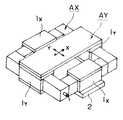
従来のこの種の2軸移動装置としては、例えば特開平4−294947号公報に開示されたものがある(第1従来例)。このものは、図6に示すように、移動用案内軸としての四角い枠型のX方向可動体AXと、この可動体AX上に重ね合わせて組み付けたステージとしての長方形テーブル状のY方向可動体AYとを有する。X方向可動体AXは、4本の枠軸のうちの相対する2本の軸が静圧気体軸受(エアスライド)1X を介して固定台2上に支持され、枠全体でX方向に移動可能になっている。Y方向可動体AYは、可動体AXの残り2本の軸上に静圧気体軸受(エアスライド)1Y を介してY方向に移動可能に支持されている。そして、各可動体AX,AYはそれぞれに設置した駆動用モータで独立に直線駆動されるようになっている。すなわち、X方向可動体AXは固定台2に固定して設置した図外の駆動用モータによりギヤ機構を介してX方向に移動し、Y方向可動体AYの方は静圧気体軸受1Y に一体的に移動可能に設置した図外の駆動用モータによりギヤ機構を介してY方向に移動するものである。
【0003】
また、特開平8−229759号公報には、図7に示すような2軸移動装置が開示されている(第2従来例)。このものは、定盤55上に、Y方向移動体であるYステージ54が載置され、そのYステージ54にX方向移動体であるXステージ51が組み付けられている。Yステージ54は、可動式のXステージ水平方向ガイド54bの両端部の軸受取付板54aの下端面に備えた鉛直方向静圧気体軸受53dにより定盤55上に浮上支持されると共に、その一方の軸受取付板54aの外側面に備えた水平方向静圧気体軸受53cにより、片側に設けられている固定式のYステージ水平方向ガイド52に案内されて、両側に設置されたリニアモータの如き駆動アクチュエータ54cにより、Y方向に移動される。
【0004】
Xステージ51は、被搬送体が装着される移動板51aを支持すると共に、前記可動式のXステージ水平方向ガイド54bを囲む水平方向軸受取付板51bと鉛直方向軸受取付板51cを備えている。そして、水平方向軸受取付板51bの内側面に備えた静圧気体軸受53a及び鉛直方向軸受取付板51cの下面に備えた静圧気体軸受53bにより、Xステージ水平方向ガイド54bに案内されつつ、定盤55から浮上されて、駆動アクチュエータ51cによりX方向に移動される。
【0005】
そして、Xステージ51及びYステージ54に複数の予圧用磁石ユニット56を設け且つ定盤55と固定ガイド52を磁性体で構成することにより、両ステージが常に一定の姿勢となるように調整している。
【0006】
【発明が解決しようとする課題】
しかしながら、上記第1の従来例の2軸移動装置には、次のような問題点がある。
【0007】
▲1▼真直度の悪化
上軸であるY方向可動体AYにかかる重量が、下軸であるX方向可動体AXに直接に負荷される。しかも、Y方向可動体AYがそのストローク端にいる場合と、ストローク中央にいる場合とでは、下軸に対する重量負担が変化する。特に、合成XY運動可能なテーブルであるY方向可動体AY上に重量物が搭載された場合には、変化する負担重量と下軸の軸受剛性との兼ね合いで上軸の真直度が悪化する。
【0008】
▲2▼軸受剛性の低下
上軸(可動体AY)と下軸(可動体AX)との軸受剛性が直列ばねとなり、最終的にXY運動可能なテーブルであるY方向可動体AYの上面では次式のように軸受剛性が低下する。
【0009】
Kz=1/(1/Kx+1/Ky)
Kz:XY運動するテーブル上面での軸受剛性(ばね定数)
Kx:上軸(可動体AY)単独の剛性(ばね定数)
Ky、下軸(可動体AX)単独の剛性(ばね定数)
▲3▼高コスト
一般的に気体軸受は加工精度が厳しく、また精度維持のためにセラミックスを使うなどのために、コストが高い。これをX軸とY軸との双方に使用するので高価になる。
【0010】
一方、上記第2の従来例は、基台(定盤)55が磁性材(鉄)であることから、以下のような問題点を有している。
▲1▼耐焼付き性が低い
基台55と対向している静圧軸受(53b,53d)が、何らかのアクシデントで基台に接触するようなことがあった場合、鉄製の基台との間に焼付きが生じやすい。
【0011】
▲2▼経年変化しやすい
基台55が腐食などで経年変化を起こしやすいため、基台上面を基準面とした静圧軸受部の運動精度が変化し易くなる。
【0012】
▲3▼塑性変形しやすい
装置の組立調整時や使用中に基台55の基準面が衝撃を受けると、軽微な衝撃であっても打痕等の塑性変形が生じる。静圧軸受と基準面との間の軸受すき間は微小であるから、僅かな打痕でも装置の運動精度に影響する。
【0013】
本発明は、このような従来の2軸移動装置の問題点を解決することを課題とするもので、その目的とするところは、真直度,剛性が高くて運動再現性などに優れた安価な2軸移動装置を提供することにある。
【0014】
【課題を解決するための手段】
上記の目的を達成するために、請求項1に係る本発明は、X方向の可動体とY方向の可動体とを備えた2軸移動装置において、前記X方向可動体は転がり案内軸受を介して基台上に支持されると共に両サイド部に立ち上げ面を有し、前記Y方向可動体は上下方向静圧気体軸受を介して基台上に支持されると共に前記X方向可動体の上面と対向する下面を有し、前記Y方向可動体の下面に二つの水平方向静圧気体軸受を前記立ち上げ面に対向するように互いに平行に配設するとともに、前記X方向可動体の上面にリニアモータの固定子をY方向に沿って配設し、かつ前記リニアモータの移動子を前記Y方向可動体の下面に取り付けたことを特徴とする。
【0015】
また、請求項2に係る発明は、請求項1記載の2軸移動装置において、前記X方向可動体の上面と前記Y方向可動体の下面との間に上下方向の磁気吸引部を設けたことを特徴とする。
【0016】
【発明の実施の形態】
以下、本発明の実施の形態を図面を参照して説明する。
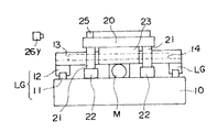
図1〜図4は本発明の一実施の形態を示すもので、図1は本発明の2軸移動装置の平面図、図2はそのII矢視で示す側面図、図3は図1のIII 矢視で示す側面図 、図4は図1のIV−IV線断面図である。図に例示したものは、XY平面上で自在にステップ&スキャン運動を繰り返すことができるタイプで、X軸がステップ位置決め、Y軸が等速スキャンする。半導体製造工程などで好適に用いることができるものであるが、本発明をこのタイプに限定するものではない。
【0017】
基台10の上に、転がり案内軸受である直動案内軸受(リニアガイド)LGのガイドレール11を2本、Y方向に間隔をおいて平行に並べてX方向に長く固定して取り付けている。その各ガイドレール11上には、それぞれ2個ずつのスライダ12を装着してある。その2本のガイドレール11を跨ぐようにして、各スライダ12の上面に、一方の可動体としてX方向の可動体13が載置固定されている。このX方向可動体13は、断面が凹形状で、幅方向の両サイド部に立ち上げ面13aを形成している。また、その溝底をなす上面13bのセンターラインに沿ってリニアモータLMの固定子14が長手方向に配設されている。なお、リニアモータLMの移動子15の方は、後述のY方向可動体の裏面に固定して取り付ける。
【0018】
基台10の上面には、また前記2本のガイドレール11,11と平行に、その中間の任意の位置に1個のボールねじBSを、ベアリング17を介して配設してある。そのボールねじBSのねじ軸18の一端は、基台10の上に固定して配設した回転駆動モータM(例えばDCサーボモータ,ACサーボモータあるいはステップモータなど)の出力軸に連結してある。そして、ボールねじBSのナット19が、図4に示すように、X方向の可動体13の下面に取り付けてある。かくして、X方向の可動体13は、基台10に固定したリニアガイドLGで支持,案内されつつ回転駆動モータMとボールねじBSとによりX方向に円滑に直線移動可能である。
【0019】
他方の可動体であるY方向の可動体20は、ほぼ正方形のテーブル板である。その下面の四隅にそれぞれ支柱21を下方に向けて立設すると共に、各支柱21の下端部に上下方向の支持機能を有する静圧気体軸受(エアパッド)22を基台10の面に対向して設けている。この上下方向静圧気体軸受22により、Y方向の可動体20は基台10の面上を非接触で移動自在である。Y方向の可動体20の下面には、更に、水平方向の支持機能を有する静圧気体軸受(エアパッド)23を、X方向の可動体13の両サイド部の立ち上げ面13aに僅かのすき間を介して対向するように2枚平行に配設している。この水平方向静圧気体軸受23により、X方向の可動体13のX方向の直線移動がY方向可動体20に非接触で伝達可能である。
【0020】
また、先に述べたように、X方向可動体13に設けたリニアモータLMの移動子15をY方向可動体20の下面に取り付けてあるから、Y方向可動体20は当該移動子15の運動に伴いY方向に移動可能である。その場合、前記水平方向静圧気体軸受23がX方向可動体13の立ち上げ面13aを案内面として可動体20と共にY方向に移動して、Y方向可動体20の移動を非接触で抵抗なく滑らかに案内する。
【0021】
Y方向の可動体20の位置検出のため、その上面にL型ミラー25を設置すると共に、これに対向させて2方向のレーザ測長器26x,26yを外部に配設してある。
【0022】
次に、作用を述べる。
この2軸移動装置は、回転駆動モータMの作動をボールねじBSの作動を介してX方向の可動体13に伝達することにより、X方向の可動体13をX方向に移動させる。すると、水平方向の支持機能を有する静圧気体軸受(エアパッド)23を介して係合しているY方向の可動体20も、X方向の可動体13の移動に連動してX方向に移動する。その移動位置(距離)がL型ミラー25の一辺に対向配置されたレーザ測長器26xにより測定され、位置情報として図外の制御装置にフィードバックされる。制御装置は予め入力してある設定位置と比較して回転駆動モータMの作動を制御する。これによりX方向可動体13ひいてはY方向可動体20のX方向のステップ位置決めを正確に行うことができる。一方、X方向可動体13に搭載したリニアモータLMの固定子14のコイルに通電することにより、Y方向可動体20がY方向に等速移動する。その移動位置(距離)がL型ミラー25の他辺に対向配置されたレーザ測長器26yにより測定され、位置情報として図外の制御装置にフィードバックされる。制御装置は予め入力してある設定位置と比較してリニアモータLMの作動を制御する。これによりY方向可動体20のY方向の位置決めを正確に行うことができる。
【0023】
上記の作動において、X軸を構成するX方向可動体13を支承するリニアガイドLGの転がり振動や、駆動用ボールねじBSの振れ回りなどが避けられず、これらは真直度に悪影響を及ぼす成分である。しかし本発明にあっては、X方向可動体13とY方向可動体20とが非接触の水平方向静圧気体軸受23により隔離されており、それらの悪影響がY方向可動体20に及ぶことはない。
【0024】
また、Y方向可動体20で構成されるXYテーブル上に重量物を搭載して移動させた場合も、Y方向可動体20の荷重は全て上下方向静圧気体軸受22を介して基台10に直接支承されており、XYテーブルの自在な二次元運動が軸への偏荷重を生じることはなく、真直度が悪化しにくい。換言すれば、本2軸移動装置は真直度,軸受剛性,運動再現性などの諸元が非常に良好である。さらに、Y方向可動体20の四隅に静圧気体軸受22を配置したので、最も安定良くY方向可動体20を支持できる。
【0025】
しかも、高価な空気軸受の使用をY軸のみとしてX軸には安価なリニアガイドを使用したため低コスト化できる。
なお、本発明の装置に用いる静圧気体軸受としては、自成絞り形,オリフィス絞り形,表面絞り形,スロット絞り形,多孔質絞り形等の公知の静圧式軸受を任意に選定することができる。
【0026】
また、リニアモータについても特に限定はされず、ACリニア誘導モータ,ACリニア同期モータ,リニアパルスモータ,DCリニアモータ,DCブラシレスリニアモータ,ボイスコイルモータ,コア無し又はコア付モータ,複合形のリニアハイブリッドモータ等を任意に選定することができる。
【0027】
また、上記実施形態では、X方向可動体13の駆動源として回転駆動モータとボールねじとを組み合わせて使用するものを示したが、リニアモータを用いることもできる。
【0028】
また、位置検出にレーザ測長器を用いL形ミラーと組み合わせた例を述べたが、リニアエンコーダのような他の測定器でもかまわない。
また、図2のX−Y面は、水平面でも傾斜面でも良い。
【0029】
また、上記実施形態では、ボールねじBSを2本のガイドレール11,11の中間の任意の位置に配設するものとしたが、特に両ガイドレールの中央位置に配置すれば、可動体13,20のヨーイングを防止できる。
【0030】
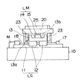
続いて、図4に対応する断面図である図5を参照して本発明の他の実施の形態を説明する。なお、上記第1の実施の形態と同一乃至相当部分には同一の符号を付して、重複する説明を省略する。
【0031】
図5に示すように、この実施の形態では、X方向の可動体13とY方向の可動体20との対向する面の間に上下方向の磁気吸引部30を設けている点が、上記第1の実施の形態とは異なっている。図示のものは、当該磁気吸引部30を構成する永久磁石31をY方向の可動体20の下面に配設し、磁性体よりなる吸引材32を磁気ギャップを隔ててX方向の可動体13の上面に配設しているが、この配置は逆にしてもよい。
【0032】
この磁気吸引部30に作用する磁気吸引力により、Y方向の可動体20を基台10上に浮上支持する上下方向静圧気体軸受22に対し下方向に予圧が負荷される。そして、Y方向の可動体20は、第1の実施の形態の場合に比べて上下方向に強く拘束される。その結果、荷重を直接に受けるY方向の可動体20の上下方向の剛性は一層高くなり、より安定する。
【0033】
しかも、X方向の可動体13の方は転がり案内軸受であるリニアガイドLGにより基台10上に支持されているから、第2の従来例のようにXステージ,Yステージとも静圧軸受により基台上に浮上支持されたものより高い真直度,剛性,運動再現性を備えた2軸移動装置を実現させることができる。且つ、鉄製の基台に代えてセラミックスや石などを用いた基台10が使用可能であり、静圧軸受と基台との焼付きが防止でき、また基台の経年変化や打痕等の塑性変形が起こりにくくて、軸受の運動精度が安定する。
【0034】
【発明の効果】
以上説明したように、請求項1に係る2軸移動装置によれば、一方の軸の支持を安価な転がり案内軸受で行い、他方の軸は静圧気体軸受で支持して荷重を基台で受けるため、XY運動中に偏荷重となることがなく、低コストで高真直度,高軸受剛性であり良好な運動再現性が得られる。
【0035】
また、請求項2に係る2軸移動装置によれば、X方向可動体の上面とY方向可動体の下面との間に磁気吸引部を設けてその磁気吸引力の作用で上下方向静圧気体軸受に予圧を負荷したため、Y方向可動体の耐荷重剛性を向上できて、その結果、上記請求項1の場合より高い真直度,剛性,運動再現性が得られると同時に、加えて、セラミックスや石などの基台の採用により、静圧軸受の焼付き防止、更に基台の経年変化や塑性変形による軸受の運動精度の低下も阻止できるという効果を奏する。
【図面の簡単な説明】
【図1】本発明の一実施形態の平面図である。
【図2】図1のII矢視図である。
【図3】図1のIII 矢視図である。
【図4】図1のIV−IV線断面図である。
【図5】本発明の他の実施形態の、図4に相当する断面図である。
【図6】従来例の2軸移動装置の斜視図である。
【図7】他の従来例の2軸移動装置で、(a)は側面図、(b)は下面図、(c)はA−A断面図である。
【符号の説明】
10 基台
13 X方向の可動体
20 Y方向の可動体
22 上下方向静圧気体軸受
23 水平方向静圧気体軸受
LG 転がり案内軸受(リニアガイド)
30 磁気吸引部
31 磁石
32 吸引材[0001]
BACKGROUND OF THE INVENTION
The present invention relates to a two-axis moving apparatus suitable for moving a sample, a tool, a detector, etc. with high positional accuracy in a highly accurate processing apparatus, measuring apparatus, semiconductor manufacturing apparatus, inspection apparatus, or the like.
[0002]
[Prior art]
As this type of conventional biaxial moving device, for example, there is one disclosed in JP-A-4-294947 (first conventional example). As shown in FIG. 6, a rectangular frame-shaped X-direction movable body AX as a moving guide shaft and a rectangular table-shaped Y-direction movable body as a stage assembled on the movable body AX are assembled. AY. The X-direction movable body AX is supported on the fixed base 2 via two static pressure gas bearings (air slides) 1X among the four frame shafts, and can move in the X direction over the entire frame. It has become. The Y-direction movable body AY is supported on the remaining two shafts of the movable body AX so as to be movable in the Y direction via a static pressure gas bearing (air slide) 1Y. And each movable body AX, AY is linearly driven independently by the drive motor installed in each. That is, the X-direction movable body AX is moved in the X direction through a gear mechanism by a driving motor (not shown) fixed to the fixed base 2, and the Y-direction movable body AY is integrated with the static pressure gas bearing 1Y. It is moved in the Y direction via a gear mechanism by a drive motor (not shown) that is movably installed.
[0003]
JP-A-8-229759 discloses a biaxial moving device as shown in FIG. 7 (second conventional example). In this apparatus, a
[0004]
The
[0005]
Then, by providing a plurality of preloading
[0006]
[Problems to be solved by the invention]
However, the biaxial movement device of the first conventional example has the following problems.
[0007]
(1) Deterioration of straightness The weight applied to the Y-direction movable body AY, which is the upper axis, is directly applied to the X-direction movable body AX, which is the lower axis. And the weight burden with respect to a lower axis changes with the case where the Y direction movable body AY exists in the stroke end, and the case where it exists in the center of a stroke. In particular, when a heavy object is mounted on the Y-direction movable body AY, which is a table capable of synthetic XY movement, the straightness of the upper shaft deteriorates due to the balance between the changing load weight and the bearing rigidity of the lower shaft.
[0008]
(2) Decrease in bearing rigidity The bearing rigidity of the upper shaft (movable body AY) and the lower shaft (movable body AX) becomes a series spring, and finally on the upper surface of the Y-direction movable body AY, which is a table capable of XY movement. The bearing rigidity decreases as in the equation.
[0009]
Kz = 1 / (1 / Kx + 1 / Ky)
Kz: Bearing stiffness (spring constant) on the top surface of the XY moving table
Kx: Upper shaft (movable body AY) independent rigidity (spring constant)
Ky, lower shaft (movable body AX) independent rigidity (spring constant)
(3) High cost In general, gas bearings have high processing accuracy and are expensive due to the use of ceramics to maintain accuracy. Since this is used for both the X axis and the Y axis, it becomes expensive.
[0010]
On the other hand, the second conventional example has the following problems because the base (surface plate) 55 is a magnetic material (iron).
(1) If the hydrostatic bearings (53b, 53d) facing the
[0011]
{Circle around (2)} Since the
[0012]
(3) When the reference surface of the
[0013]
An object of the present invention is to solve such problems of the conventional biaxial moving device. The object of the present invention is to provide a low-cost, high straightness, high rigidity and excellent motion reproducibility. It is to provide a biaxial moving device.
[0014]
[Means for Solving the Problems]
In order to achieve the above object, the present invention according to claim 1 is a biaxial moving device including a movable body in the X direction and a movable body in the Y direction, and the movable body in the X direction is interposed via a rolling guide bearing. It has a raised surface standing on both side portions while being supported on a base Te, an upper surface of the X-direction movable body together with the Y-direction movable body is supported on the base via a vertically externally pressurized gas bearing And two horizontal static pressure gas bearings are arranged in parallel to each other on the lower surface of the Y-direction movable body so as to face the rising surface, and on the upper surface of the X-direction movable body. The linear motor stator is disposed along the Y direction, and the linear motor movable element is attached to the lower surface of the Y direction movable body .
[0015]
According to a second aspect of the present invention, in the biaxial moving device according to the first aspect, a vertical magnetic attraction unit is provided between the upper surface of the X-direction movable body and the lower surface of the Y-direction movable body. It is characterized by.
[0016]
DETAILED DESCRIPTION OF THE INVENTION
Hereinafter, embodiments of the present invention will be described with reference to the drawings.
1 to 4 show an embodiment of the present invention. FIG. 1 is a plan view of a biaxial moving device according to the present invention, FIG. 2 is a side view taken along the line II, and FIG. FIG. 4 is a sectional view taken along line IV-IV in FIG. The example shown in the figure is a type in which the step & scan motion can be freely repeated on the XY plane. The X axis performs step positioning and the Y axis performs constant speed scanning. Although it can be used suitably in a semiconductor manufacturing process etc., this invention is not limited to this type.
[0017]
Two guide rails 11 of linear motion guide bearings (linear guides) LG, which are rolling guide bearings, are arranged on the base 10 in parallel in the Y direction with a long interval in the X direction. Two
[0018]
On the upper surface of the
[0019]
The other movable body Y-direction
[0020]
As described above, since the moving
[0021]
In order to detect the position of the
[0022]
Next, the operation will be described.
This two-axis moving device moves the X-direction
[0023]
In the above operation, rolling vibration of the linear guide LG supporting the X-direction
[0024]
Further, even when a heavy object is mounted and moved on an XY table composed of the Y-direction
[0025]
In addition, the use of an expensive air bearing is limited to the Y axis, and an inexpensive linear guide is used for the X axis, so that the cost can be reduced.
As the hydrostatic gas bearing used in the apparatus of the present invention, a known hydrostatic bearing such as a self-contained throttle type, an orifice throttle type, a surface throttle type, a slot throttle type, or a porous throttle type may be arbitrarily selected. it can.
[0026]
Also, the linear motor is not particularly limited. An AC linear induction motor, an AC linear synchronous motor, a linear pulse motor, a DC linear motor, a DC brushless linear motor, a voice coil motor, a coreless or cored motor, a composite linear A hybrid motor or the like can be arbitrarily selected.
[0027]
In the above-described embodiment, a combination of a rotary drive motor and a ball screw is used as a drive source for the X-direction
[0028]
Moreover, although the example which combined the L-shaped mirror using the laser length measuring device for position detection was described, other measuring devices like a linear encoder may be used.
2 may be a horizontal plane or an inclined plane.
[0029]
In the above embodiment, the ball screw BS is disposed at an arbitrary position between the two guide rails 11, 11. However, if the ball screw BS is disposed at the center position between both guide rails, the
[0030]
Next, another embodiment of the present invention will be described with reference to FIG. 5 which is a sectional view corresponding to FIG. In addition, the same code | symbol is attached | subjected to the same thru | or equivalent part as the said 1st Embodiment, and the overlapping description is abbreviate | omitted.
[0031]
As shown in FIG. 5, in this embodiment, the vertical
[0032]
Due to the magnetic attractive force acting on the magnetic
[0033]
Moreover, since the
[0034]
【The invention's effect】
As described above, according to the two-axis moving device according to the first aspect, one shaft is supported by an inexpensive rolling guide bearing, and the other shaft is supported by a static pressure gas bearing and the load is supported by the base. Therefore, there is no uneven load during XY motion, and high motion straightness and high bearing rigidity are obtained at low cost and good motion reproducibility can be obtained.
[0035]
Further, according to the biaxial moving device according to claim 2, a magnetic attraction portion is provided between the upper surface of the X-direction movable body and the lower surface of the Y-direction movable body, and the vertical static pressure gas is produced by the action of the magnetic attraction force. Since the preload is applied to the bearing, the load bearing rigidity of the movable body in the Y direction can be improved. As a result, higher straightness, rigidity and motion reproducibility can be obtained than in the case of claim 1 above. By adopting a base such as stone, it is possible to prevent seizure of the hydrostatic bearing and to prevent a decrease in the motion accuracy of the bearing due to aging of the base and plastic deformation.
[Brief description of the drawings]
FIG. 1 is a plan view of an embodiment of the present invention.
FIG. 2 is a view taken in the direction of arrow II in FIG.
FIG. 3 is a view taken in the direction of arrow III in FIG.
4 is a cross-sectional view taken along line IV-IV in FIG.
FIG. 5 is a cross-sectional view corresponding to FIG. 4 of another embodiment of the present invention.
FIG. 6 is a perspective view of a conventional biaxial moving device.
7A is a side view, FIG. 7B is a bottom view, and FIG. 7C is a cross-sectional view along line AA. FIG.
[Explanation of symbols]
10
30
Claims (3)
Priority Applications (1)
| Application Number | Priority Date | Filing Date | Title |
|---|---|---|---|
| JP26634998A JP3687362B2 (en) | 1998-03-31 | 1998-09-21 | 2-axis moving device |
Applications Claiming Priority (3)
| Application Number | Priority Date | Filing Date | Title |
|---|---|---|---|
| JP8724798 | 1998-03-31 | ||
| JP10-87247 | 1998-03-31 | ||
| JP26634998A JP3687362B2 (en) | 1998-03-31 | 1998-09-21 | 2-axis moving device |
Publications (2)
| Publication Number | Publication Date |
|---|---|
| JPH11344585A JPH11344585A (en) | 1999-12-14 |
| JP3687362B2 true JP3687362B2 (en) | 2005-08-24 |
Family
ID=26428540
Family Applications (1)
| Application Number | Title | Priority Date | Filing Date |
|---|---|---|---|
| JP26634998A Expired - Fee Related JP3687362B2 (en) | 1998-03-31 | 1998-09-21 | 2-axis moving device |
Country Status (1)
| Country | Link |
|---|---|
| JP (1) | JP3687362B2 (en) |
Cited By (1)
| Publication number | Priority date | Publication date | Assignee | Title |
|---|---|---|---|---|
| US8517363B2 (en) | 2009-03-18 | 2013-08-27 | Sumitomo Heavy Industries, Ltd. | XY stage device, semiconductor inspection apparatus, and semiconductor exposure apparatus |
Families Citing this family (8)
| Publication number | Priority date | Publication date | Assignee | Title |
|---|---|---|---|---|
| JP2007232648A (en) * | 2006-03-02 | 2007-09-13 | Sumitomo Heavy Ind Ltd | Stage device |
| JP4877925B2 (en) * | 2006-03-02 | 2012-02-15 | 住友重機械工業株式会社 | Stage equipment |
| JP5242218B2 (en) * | 2008-03-31 | 2013-07-24 | 住友重機械工業株式会社 | XY stage device |
| CN103617812B (en) * | 2013-11-20 | 2015-10-14 | 贵州航天南海科技有限责任公司 | A kind of translation device |
| CN103934749B (en) * | 2014-04-25 | 2016-05-25 | 厦门安达兴精密机械有限公司 | Grinding machine linear rolling track is installed bearing calibration and device |
| JP2019214087A (en) * | 2018-06-12 | 2019-12-19 | 東芝機械株式会社 | Guide mechanism of machine tool and machine tool |
| WO2020044685A1 (en) * | 2018-08-30 | 2020-03-05 | 住友重機械工業株式会社 | Stage device |
| CN111958220B (en) * | 2020-07-31 | 2022-07-12 | 伯肯森自动化技术(上海)有限公司 | Screw locking device for precisely positioning locking position of set top box |
-
1998
- 1998-09-21 JP JP26634998A patent/JP3687362B2/en not_active Expired - Fee Related
Cited By (1)
| Publication number | Priority date | Publication date | Assignee | Title |
|---|---|---|---|---|
| US8517363B2 (en) | 2009-03-18 | 2013-08-27 | Sumitomo Heavy Industries, Ltd. | XY stage device, semiconductor inspection apparatus, and semiconductor exposure apparatus |
Also Published As
| Publication number | Publication date |
|---|---|
| JPH11344585A (en) | 1999-12-14 |
Similar Documents
| Publication | Publication Date | Title |
|---|---|---|
| US7152331B2 (en) | Positioning apparatus | |
| US6552449B2 (en) | Stage system with onboard linear motor | |
| US5939852A (en) | Stage feeding device | |
| US8109395B2 (en) | Gantry positioning system | |
| JP4160824B2 (en) | Elevating guide unit and stage device incorporating the same | |
| KR100591939B1 (en) | Stage apparatus | |
| CA2777465C (en) | Motorized stage | |
| US20010019250A1 (en) | Exposure apparatus and method utilizing isolated reaction frame | |
| JP2007266585A (en) | Stage apparatus | |
| JP3687362B2 (en) | 2-axis moving device | |
| US11795004B2 (en) | Conveyor table transfer apparatus, transport system and conveyor table transfer method | |
| JPH03245932A (en) | Travelling guide device | |
| TWI260646B (en) | X-Y axis stage device | |
| JP4322762B2 (en) | Stage guide mechanism | |
| JP2003028973A (en) | Stage apparatus | |
| US6715426B1 (en) | Motor driven high stability brake linear motion systems | |
| JP2004317485A (en) | X-y stage device | |
| JP4116167B2 (en) | Static pressure air bearing linear guide device | |
| JPH07276166A (en) | X-y table | |
| JP2952166B2 (en) | Portal drive | |
| JP2006287098A (en) | Positioning device | |
| JPH11280761A (en) | Linear motion rolling guide unit and XY table device using the same | |
| JP2655335B2 (en) | Linear motion guide linear motor drive table | |
| JP7603677B2 (en) | Conveyor table transfer device, transport system and conveyor table transfer method | |
| JPH03293586A (en) | Positioning table apparatus |
Legal Events
| Date | Code | Title | Description |
|---|---|---|---|
| A131 | Notification of reasons for refusal |
Free format text: JAPANESE INTERMEDIATE CODE: A131 Effective date: 20050301 |
|
| A521 | Written amendment |
Free format text: JAPANESE INTERMEDIATE CODE: A523 Effective date: 20050412 |
|
| TRDD | Decision of grant or rejection written | ||
| A01 | Written decision to grant a patent or to grant a registration (utility model) |
Free format text: JAPANESE INTERMEDIATE CODE: A01 Effective date: 20050517 |
|
| A61 | First payment of annual fees (during grant procedure) |
Free format text: JAPANESE INTERMEDIATE CODE: A61 Effective date: 20050530 |
|
| R150 | Certificate of patent (=grant) or registration of utility model |
Free format text: JAPANESE INTERMEDIATE CODE: R150 |
|
| FPAY | Renewal fee payment (prs date is renewal date of database) |
Free format text: PAYMENT UNTIL: 20080617 Year of fee payment: 3 |
|
| FPAY | Renewal fee payment (prs date is renewal date of database) |
Free format text: PAYMENT UNTIL: 20090617 Year of fee payment: 4 |
|
| FPAY | Renewal fee payment (prs date is renewal date of database) |
Free format text: PAYMENT UNTIL: 20100617 Year of fee payment: 5 |
|
| FPAY | Renewal fee payment (prs date is renewal date of database) |
Free format text: PAYMENT UNTIL: 20100617 Year of fee payment: 5 |
|
| FPAY | Renewal fee payment (prs date is renewal date of database) |
Free format text: PAYMENT UNTIL: 20110617 Year of fee payment: 6 |
|
| LAPS | Cancellation because of no payment of annual fees |