JP3685486B2 - Shooting lens - Google Patents
Shooting lens Download PDFInfo
- Publication number
- JP3685486B2 JP3685486B2 JP2001271624A JP2001271624A JP3685486B2 JP 3685486 B2 JP3685486 B2 JP 3685486B2 JP 2001271624 A JP2001271624 A JP 2001271624A JP 2001271624 A JP2001271624 A JP 2001271624A JP 3685486 B2 JP3685486 B2 JP 3685486B2
- Authority
- JP
- Japan
- Prior art keywords
- lens
- positive
- image
- optical axis
- positive meniscus
- Prior art date
- Legal status (The legal status is an assumption and is not a legal conclusion. Google has not performed a legal analysis and makes no representation as to the accuracy of the status listed.)
- Expired - Fee Related
Links
Images


Classifications
-
- G—PHYSICS
- G02—OPTICS
- G02B—OPTICAL ELEMENTS, SYSTEMS OR APPARATUS
- G02B13/00—Optical objectives specially designed for the purposes specified below
- G02B13/001—Miniaturised objectives for electronic devices, e.g. portable telephones, webcams, PDAs, small digital cameras
- G02B13/0015—Miniaturised objectives for electronic devices, e.g. portable telephones, webcams, PDAs, small digital cameras characterised by the lens design
- G02B13/002—Miniaturised objectives for electronic devices, e.g. portable telephones, webcams, PDAs, small digital cameras characterised by the lens design having at least one aspherical surface
- G02B13/003—Miniaturised objectives for electronic devices, e.g. portable telephones, webcams, PDAs, small digital cameras characterised by the lens design having at least one aspherical surface having two lenses
-
- G—PHYSICS
- G02—OPTICS
- G02B—OPTICAL ELEMENTS, SYSTEMS OR APPARATUS
- G02B13/00—Optical objectives specially designed for the purposes specified below
- G02B13/18—Optical objectives specially designed for the purposes specified below with lenses having one or more non-spherical faces, e.g. for reducing geometrical aberration
-
- G—PHYSICS
- G02—OPTICS
- G02B—OPTICAL ELEMENTS, SYSTEMS OR APPARATUS
- G02B9/00—Optical objectives characterised both by the number of the components and their arrangements according to their sign, i.e. + or -
- G02B9/04—Optical objectives characterised both by the number of the components and their arrangements according to their sign, i.e. + or - having two components only
Landscapes
- Physics & Mathematics (AREA)
- General Physics & Mathematics (AREA)
- Optics & Photonics (AREA)
- Lenses (AREA)
Description
【0001】
【発明の属する技術分野】
本発明は、主として小型の電子機器、例えば光センサー、携帯用モジュールカメラおよびWEBカメラなどに使用される撮影レンズに関する。
【0002】
【従来の技術】
近年、CCD(電荷結合素子)などの撮像素子の小型化に伴い、それを用いた電子機器も小型化してきている。例えば、光センサー、携帯用モジュールカメラおよびWEBカメラなどの電子機器は、小型化が著しい。なお、携帯用モジュールカメラとは、携帯電話などに用いられるものであり、WEBカメラとは、例えばインターネットを介した画像データの送信に用いられるものである。これら小型の電子機器で使用される撮影レンズは、小型、携帯性を重視して1枚のレンズのみで構成されていることが多い。
【0003】
【発明が解決しようとする課題】
ところで、近年では、撮像素子の性能が向上し、小型のものでも高画素化が図られてきている(例えば35万画素程度)。このような高画素化に伴い、それに利用される撮影レンズにも従来より高い光学性能が要求され、1枚玉のレンズ構成では十分な性能を満足できないという問題が生じてきている。特に、1枚玉のレンズ構成では、周辺部の性能が著しく低下するという問題がある。この周辺部の性能の低下は、サジタル像面とタンジェンシャル像面との結像位置の違い、すなわち非点較差に起因するものである。
【0004】
そこで、近年の撮像素子の高画素化に耐えうる光学性能を得るために、レンズの枚数を増やして2枚にすることが考えられる。2枚構成の撮影レンズとしては、従来、負レンズと正レンズとを組み合わせたものがある。しかしながら、このような従来の2枚構成の撮影レンズでは、特に全長の点で十分な性能を有しているものが少ない。そこで、小型、高画素化の図られた撮像素子に適した撮影レンズ、すなわち、レンズの枚数を増やしたとしても、全長を長くすることなく、光学性能を向上させることのできる撮影レンズの開発が望まれる。例えば撮像素子も含めて10cm3程度の大きさに収めることのできる小型、高性能の撮影レンズの開発が望まれる。
【0005】
本発明はかかる問題点に鑑みてなされたもので、その目的は、全長が短く、1枚構成の撮影レンズに比べて特に周辺性能の向上を図ることができる撮影レンズを提供することにある。
【0006】
【課題を解決するための手段】
本発明による撮影レンズは、両凸形状で、かつ両面が非球面で構成された正レンズと、像面側に凸面を向け、かつ両面が非球面で構成された正メニスカスレンズとの2枚のレンズが物体側から順に配設されて構成されると共に、正メニスカスレンズの像側の非球面が、光軸から周辺に向かうに従い、正の屈折力を弱めるような形状とされ、かつ、以下の条件式(1),(2)を満足するように構成されていることを基本構成としている。
【0007】
2*dd2<dd1 ……(1)
R3<R4 ……(2)
ただし、dd1は、正レンズの物体側の面と像側の面との光軸上における面間隔を示す。dd2は、正レンズの像側の面と正メニスカスレンズの物体側の面との光軸上における面間隔を示す。R3は、正レンズの像側の面の曲率半径を示し、R4は、正メニスカスレンズの物体側の面の曲率半径を示す。
【0008】
本発明による撮影レンズでは、この基本構成により、全長を長くすることなく、諸収差が良好に補正され、従来の1枚玉の撮影レンズに比べて光学性能の向上が図られる。
【0009】
特に、正メニスカスレンズの像側の非球面が、光軸から周辺に向かうに従い、正の屈折力を弱めるような形状となっていることにより、サジタル像面とタンジェンシャル像面との結像位置を合わせることが容易となり、周辺部の性能を向上させることができる。
【0010】
本発明による撮影レンズは、正レンズおよび正メニスカスレンズのd線に対するアッベ数νd1,νd2に関して、以下の条件式(3),(4)を満足するように構成されていることが望ましい。条件式(3),(4)を満足することにより、特に、倍率色収差が軽減される。
νd1>50 ……(3)
νd2<35 ……(4)
【0011】
【発明の実施の形態】
以下、本発明の実施の形態について図面を参照して詳細に説明する。
【0012】
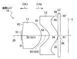
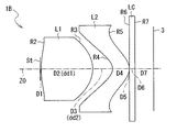
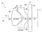
図1は、本発明の一実施の形態に係る撮影レンズの一構成例を示している。また、図2〜図5は、本実施の形態に係る撮影レンズの他の構成例を示している。図1〜図5に示した構成例は、それぞれ、後述の第1から第5の数値実施例(図6〜図10)のレンズ構成に対応している。なお、図1〜図5において、符号Zobjで示す側が物体側、すなわち、撮影用の被写体が存在する側である。また、符号Zimgで示す側が結像側(像面側)である。3は、結像面を示す。また、図1において、符号Riは、絞りStも含めて最も物体側の構成要素の面を1番目として、像面側に向かうに従い順次増加するi番目の構成要素の面の曲率半径を示す。符号Diは、i番目の面とi+1番目の面との光軸上の面間隔を示す。
【0013】
図1〜図5に示した本実施の形態に係る撮影レンズ1A〜1E(以下、1A〜1Eを総称して1と記す。)は、例えば、光センサー、携帯用モジュールカメラおよびWEBカメラなど、撮像素子を用いた小型の電子機器に利用されるものである。
【0014】
この撮影レンズ1は、光軸Z0に沿って、物体側より順に配設された2枚のレンズL1,L2を有して構成されている。絞りStは、1枚目のレンズL1よりも物体側に設けられている。2枚目のレンズL2よりも像面側には、必要に応じてカバーガラスLCが配置されていても良い。カバーガラスLCは、CCDなどの撮像素子の撮像面を保護するためのものである。なお、図では、カバーガラスLCが、結像面3と離れた位置に配置されているが、実際には、カバーガラスLCの像面側の面が、結像面3、すなわち、撮像面と一致するように配置されていることが望ましい。
【0015】
この撮影レンズ1において、1枚目のレンズL1は、両凸形状で、かつ両面が非球面の正レンズであることを基本構成としている。また、2枚目のレンズL2は、像面側に凸面を向け、かつ両面が非球面の正メニスカスレンズであることを基本構成としている。
【0016】
この撮影レンズ1は、以下の条件式(1),(2)を満足するように構成されている。式(1)において、dd1は、図にも示したとおり、正レンズL1の物体側の面と像側の面との光軸上における面間隔D2を示す。dd2は、正レンズL1の像側の面と正メニスカスレンズL2の物体側の面との光軸上における面間隔D3を示す。*は、乗算記号を示す。式(2)において、R3は、図にも示したとおり、正レンズL1の像側の面の曲率半径を示し、R4は、正メニスカスレンズL2の物体側の面の曲率半径を示す。
【0017】
2*dd2<dd1 ……(1)
R3<R4 ……(2)
【0018】
この撮影レンズ1において、正メニスカスレンズL2の像側の非球面(R5)は、光軸Z0から周辺に向かうに従い、正の屈折力(パワー)を弱めるような形状となっていることが望ましい。この場合、この非球面は、例えば中心部では像側に凸形状、周辺部では像側に凹形状となっていることが望ましい。また、正メニスカスレンズL2は、中心付近では正、周辺部では負のパワーとなるような非球面形状となっていることが望ましい。
【0019】
撮影レンズ1は、また、正レンズL1および正メニスカスレンズL2のd線に対するアッベ数νd1,νd2に関して、以下の条件式(3),(4)を満足するように構成されていることが望ましい。これらの条件は、後述する実施例4,5の撮影レンズが満足している。
【0020】
νd1>50 ……(3)
νd2<35 ……(4)
【0021】
次に、以上のような構成の撮影レンズ1によってもたらされる光学的な作用および効果について説明する。
【0022】
条件式(1)は、全長の制限と収差補正とに寄与している。条件式(1)を満足することで、全長を短くしたまま、良好に収差補正を行うことができる。条件式(1)の範囲を外れることは、2枚のレンズL1,L2の間隔が大きくなることを意味するが、この場合、特に、像面がオーバーとなってしまう。
【0023】
条件式(2)は、特に、像面およびディストーションの補正、ならびに周辺光量の確保に寄与している。この条件を外れると、サジタル像面とタンジェンシャル像面とが離れ、また、ディストーションも増大する。また、周辺光量も減少してしまう。
【0024】
既に[発明が解決しようとする課題]の項目において述べたように、従来の1枚玉の撮影レンズでは、サジタル像面とタンジェンシャル像面との結像位置の違い、すなわち非点較差により、周辺部の性能劣化が生じる。本撮影レンズ1において、特に、物体側から2番目に配置された正メニスカスレンズL2に関して、像側の非球面を、光軸Z0から周辺に向かうに従い、正の屈折力を弱める形状とし、また、中心付近では正、周辺部では負のパワーになるような非球面形状にすることで、サジタル像面とタンジェンシャル像面との結像位置を合わせることが容易となり、周辺部の性能を向上させることができる。
【0025】
条件式(3),(4)は、特に、倍率の色収差の補正に寄与している。2枚のレンズL1,L2に関しては、共に同一の材質のレンズで構成しても良いが、条件式(3),(4)を満足するような別々の材質のレンズで構成した方が、色収差が良好に補正されるので好ましい。
【0026】
このように、本実施の形態に係る撮影レンズ1によれば、上述の基本構成において適宜上述した望ましい構成を採用することにより、全長が短く、従来の1枚玉の撮影レンズに比べて、特に周辺性能の向上を図ることができ、小型、高画素化の図られた撮像素子に適した性能を得ることができる。
【0027】
[実施例](実施例1〜5)
次に、本実施の形態に係る撮影レンズ1の具体的な数値実施例について説明する。以下では、第1〜第5の数値実施例(実施例1〜5)についてまとめて説明する。
【0028】
図6(A),(B)〜図10(A),(B)は、それぞれ、図1〜図5に示した撮影レンズ1A〜1Eに対応する具体的な数値実施例としてのレンズデータを示している。より詳しくは、図6(A)〜図10(A)には、レンズデータの基本的な値を示し、図6(B)〜図10(B)には、非球面形状に関する値を示す。各図のレンズデータにおける面番号Siの欄には、各実施例の撮影レンズについて、絞りStを1番目として、像面側に向かうに従い順次増加する構成要素の面の番号を示している。なお、絞りStについてはSTOと表記して示す。曲率半径Riの欄には、図1〜図5に示した符号Riに対応させて、絞りStも含めて物体側からi番目の構成要素の面の曲率半径の値を示す。曲率半径Riの値が0の部分は、平面であることを示す。面間隔Diの欄についても、図1〜図5に示した符号Diに対応させて、物体側からi番目の面Siとi+1番目の面Si+1との光軸上の間隔を示す。曲率半径Riおよび面間隔Diの値の単位はミリメートル(mm)である。Ndj,νdjの欄には、それぞれ、物体側からj番目のレンズ要素のd線(波長λd=587.6nm)に対する屈折率およびアッベ数の値を示す。また、fは、全体の焦点距離(mm)を示す。
【0029】
図6(B)〜図10(B)に示した非球面データは、以下の式(A)によって表される非球面多項式における定数または係数である。式(A)の非球面多項式f(ρ)は、光軸Z0に直交する方向にρ軸を取って非球面の形状を表したものである。非球面は、式(A)で表される曲線を光軸Z0の周りに回転して得られる曲面である。式(B)において、x,yは、互いに光軸Z0に直交する2つの座標軸上の座標点を示す。式(B)からも分かるように、ρは、光軸Z0からレンズ面までの距離(高さ)(単位:mm)に相当する。f(ρ)の値は、光軸Z0から高さρの位置にある非球面上の点から、非球面の頂点の接平面(光軸に垂直な平面)に下ろした垂線の長さ(単位:mm)を示す。Cは、光軸近傍におけるレンズ面の近軸曲率半径Rの逆数(1/R)である。また、Kは、離心率(または円錐定数)を表し、A4,A6,A8,A10は、それぞれ4次,6次,8次,10次の非球面係数を表す。なお、図6(B)〜図10(B)に示した非球面係数を表す数値において、記号“E”は、その次に続く数値が10を底とした“べき指数”であることを示し、その10を底とした指数関数で表される数値が“E”の前の数値に乗算されることを示す。例えば、「1.0E−02」は、「1.0×10-2」であることを示す。
【0030】
f(ρ)=[Cρ2/{1+(1−K・C2・ρ2)1/2}]
+A4ρ4 +A6ρ6 +A8ρ8 +A10ρ10 ……(A)
ただし、ρ2=x2+y2 ……(B)
【0031】
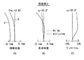
図11〜図15は、各実施例の撮影レンズについての諸収差を示している。より詳しくは、図11〜図15において、(A)は球面収差を示し、(B)は非点収差を示し、(C)はディストーション(歪曲収差)を示している。各収差図(B)において、実線はサジタル像面に対する収差を示し、破線はタンジェンシャル(メリジオナル)像面に対する収差を示している。球面収差は、g線およびd線について示す。図11〜図15の各収差図において、特に波長を明記していないものは、d線に対する収差を示す。なお、g線の波長は、435.8nmである。また、各収差図において、Fnoは、Fナンバーを、ωは半画角を示す。
【0032】
図6(A)〜図10(A)のレンズデータから分かるように、すべての実施例について、条件式(1),(2)を満たしている。また、すべての実施例について、正メニスカスレンズL2の像側の非球面R5は、中心部では像側に凸形状、周辺部では像側に凹形状であり、光軸Z0から周辺に向かうに従い、正の屈折力を弱めるような形状となっている。特に、実施例4,5については、正レンズL1および正メニスカスレンズL2のアッベ数νd1,νd2に関して、上述の条件式(3),(4)をも満足しており、像面およびディストーションが良好に補正されている。
【0033】
以上のように、すべての実施例について、全長が短く、従来の1枚玉の撮影レンズに比べて、特に周辺性能の向上が図られ、小型、高画素化の図られた撮像素子に適した性能を得ることができた。これにより、例えば撮像素子も含めて10cm3程度の大きさに収めることのできる撮影レンズを実現できる。
【0034】
なお、本発明は、上記実施の形態および各実施例に限定されず種々の変形実施が可能である。例えば、各レンズ成分の曲率半径R、面間隔Dおよび屈折率Nおよびアッベ数νの値などは、上記各数値実施例で示した値に限定されず、他の値をとり得る。
【0035】
【発明の効果】
以上説明したように、請求項1または2に記載の撮影レンズによれば、両凸形状で、かつ両面が非球面で構成された正レンズと、像面側に凸面を向け、かつ両面が非球面で構成された正メニスカスレンズとの2枚のレンズを物体側から順に配設した構成にすると共に、正メニスカスレンズの像側の非球面を、光軸から周辺に向かうに従い、正の屈折力を弱めるような形状にし、さらに、全長の制限および収差補正に寄与する所定の条件式(1)ならびに収差補正などに寄与する所定の条件式(2)を満足するように構成したので、全長が短く、1枚構成の撮影レンズに比べて特に周辺性能の向上を図ることができる。
特に、物体側から2番目に配設された正メニスカスレンズの像側の非球面を、光軸から周辺に向かうに従い、正の屈折力を弱めるような形状となるようにしたので、サジタル像面とタンジェンシャル像面との結像位置を合わせることが容易となり、周辺部の性能をさらに向上させることができる。
【0037】
特に、請求項2記載の撮影レンズによれば、請求項1記載の撮影レンズにおいて、正レンズおよび正メニスカスレンズのアッベ数に関する所定の条件式(3),(4)を満足するように構成したので、特に、倍率の色収差を軽減することができる。
【図面の簡単な説明】
【図1】本発明の一実施の形態に係る撮影レンズの一構成例を示すものであり、第1の数値実施例に対応する断面図である。
【図2】本発明の一実施の形態に係る撮影レンズの他の構成例を示すものであり、第2の数値実施例に対応する断面図である。
【図3】本発明の一実施の形態に係る撮影レンズの他の構成例を示すものであり、第3の数値実施例に対応する断面図である。
【図4】本発明の一実施の形態に係る撮影レンズの他の構成例を示すものであり、第4の数値実施例に対応する断面図である。
【図5】本発明の一実施の形態に係る撮影レンズの他の構成例を示すものであり、第5の数値実施例に対応する断面図である。
【図6】本発明の一実施の形態に係る撮影レンズの第1の数値実施例(実施例1)としてのレンズデータを示す説明図である。
【図7】本発明の一実施の形態に係る撮影レンズの第2の数値実施例(実施例2)としてのレンズデータを示す説明図である。
【図8】本発明の一実施の形態に係る撮影レンズの第3の数値実施例(実施例3)としてのレンズデータを示す説明図である。
【図9】本発明の一実施の形態に係る撮影レンズの第4の数値実施例(実施例4)としてのレンズデータを示す説明図である。
【図10】本発明の一実施の形態に係る撮影レンズの第5の数値実施例(実施例5)としてのレンズデータを示す説明図である。
【図11】実施例1の撮影レンズにおける球面収差、非点収差およびディストーションを示す収差図である。
【図12】実施例2の撮影レンズにおける球面収差、非点収差およびディストーションを示す収差図である。
【図13】実施例3の撮影レンズにおける球面収差、非点収差およびディストーションを示す収差図である。
【図14】実施例4の撮影レンズにおける球面収差、非点収差およびディストーションを示す収差図である。
【図15】実施例5の撮影レンズにおける球面収差、非点収差およびディストーションを示す収差図である。
【符号の説明】
L1…正レンズ、L2…正メニスカスレンズ、LC…カバーガラス、
St…絞り、Z0…光軸、1(1A〜1E)…撮影レンズ、3…結像面。[0001]
BACKGROUND OF THE INVENTION
The present invention relates to a photographing lens mainly used for small electronic devices such as optical sensors, portable module cameras, and WEB cameras.
[0002]
[Prior art]
In recent years, along with miniaturization of image sensors such as CCDs (charge coupled devices), electronic devices using them have also been miniaturized. For example, electronic devices such as optical sensors, portable module cameras, and WEB cameras are significantly downsized. The portable module camera is used for a mobile phone or the like, and the WEB camera is used for transmitting image data via the Internet, for example. In many cases, photographing lenses used in these small electronic devices are composed of only one lens with an emphasis on small size and portability.
[0003]
[Problems to be solved by the invention]
By the way, in recent years, the performance of the image sensor has been improved, and even with a small size, the number of pixels has been increased (for example, about 350,000 pixels). Along with such an increase in the number of pixels, higher optical performance is required for the photographing lens used therefor, and there has been a problem that sufficient performance cannot be satisfied with a single lens configuration. In particular, with a single lens configuration, there is a problem that the performance of the peripheral portion is significantly reduced. This deterioration in the performance of the peripheral portion is caused by a difference in imaging position between the sagittal image plane and the tangential image plane, that is, astigmatism difference.
[0004]
Therefore, in order to obtain optical performance that can withstand the increase in the number of pixels of recent imaging devices, it is conceivable to increase the number of lenses to two. 2. Description of the Related Art Conventionally, a two-lens photographic lens includes a combination of a negative lens and a positive lens. However, there are few conventional two-lens imaging lenses that have sufficient performance, particularly in terms of the overall length. Therefore, the development of a photographic lens suitable for an image sensor with a small size and high pixels, that is, a photographic lens capable of improving the optical performance without increasing the total length even when the number of lenses is increased. desired. For example, it is desired to develop a small and high-performance photographic lens that can be accommodated in a size of about 10 cm 3 including the image sensor.
[0005]
The present invention has been made in view of such problems, and an object of the present invention is to provide a photographic lens that has a short overall length and can particularly improve peripheral performance as compared with a photographic lens having a single lens structure.
[0006]
[Means for Solving the Problems]
The photographic lens according to the present invention includes two lenses, a positive lens having a biconvex shape and having both aspherical surfaces, and a positive meniscus lens having a convex surface facing the image surface and having both aspherical surfaces. lens is configured to be disposed in order from the object side Rutotomoni, aspherical image side of the positive meniscus lens, toward the periphery from the optical axis, is shaped to weaken the positive refractive power, and the following The basic configuration is that the conditional expressions (1) and (2) are satisfied.
[0007]
2 * dd2 <dd1 (1)
R3 <R4 (2)
Here, dd1 indicates a surface interval on the optical axis between the object-side surface and the image-side surface of the positive lens. dd2 indicates a surface interval on the optical axis between the image side surface of the positive lens and the object side surface of the positive meniscus lens. R3 represents the radius of curvature of the image side surface of the positive lens, and R4 represents the radius of curvature of the object side surface of the positive meniscus lens.
[0008]
In the photographic lens according to the present invention, various aberrations are favorably corrected without increasing the overall length, and the optical performance is improved as compared with the conventional single-lens photographic lens.
[0009]
In particular, the aspherical surface on the image side of the positive meniscus lens, toward the periphery from the optical axis, by which is shaped to weaken the positive refractive power, the imaging position of the sagittal image plane and tangential image surface It becomes easy to match, and the performance of the peripheral part can be improved.
[0010]
The photographing lens according to the present invention is preferably configured to satisfy the following conditional expressions (3) and (4) with respect to the Abbe numbers νd1 and νd2 with respect to the d-line of the positive lens and the positive meniscus lens. By satisfying conditional expressions (3) and (4), chromatic aberration of magnification is particularly reduced.
νd1> 50 (3)
νd2 <35 (4)
[0011]
DETAILED DESCRIPTION OF THE INVENTION
Hereinafter, embodiments of the present invention will be described in detail with reference to the drawings.
[0012]
FIG. 1 shows a configuration example of a photographic lens according to an embodiment of the present invention. 2 to 5 show other configuration examples of the photographing lens according to the present embodiment. The configuration examples shown in FIGS. 1 to 5 correspond to the lens configurations of first to fifth numerical examples (FIGS. 6 to 10) described later, respectively. 1 to 5, the side indicated by the reference symbol Zobj is the object side, that is, the side where the subject to be photographed exists. The side indicated by the symbol Zimg is the imaging side (image plane side).
[0013]
The photographing
[0014]
The photographing
[0015]
In this
[0016]
The taking
[0017]
2 * dd2 <dd1 (1)
R3 <R4 (2)
[0018]
In this
[0019]
The taking
[0020]
νd1> 50 (3)
νd2 <35 (4)
[0021]
Next, optical actions and effects brought about by the photographing
[0022]
Conditional expression (1) contributes to the limitation of the total length and aberration correction. By satisfying conditional expression (1), it is possible to correct aberrations satisfactorily while keeping the overall length short. Out of the range of the conditional expression (1) means that the distance between the two lenses L1 and L2 is increased. In this case, however, the image plane is particularly over.
[0023]
Conditional expression (2) contributes particularly to the correction of the image plane and distortion and the securing of the amount of peripheral light. If this condition is not satisfied, the sagittal image plane and the tangential image plane are separated from each other, and the distortion increases. Also, the amount of peripheral light is reduced.
[0024]
As already described in the section of [Problems to be Solved by the Invention], in the conventional single-lens shooting lens, due to the difference in imaging position between the sagittal image plane and the tangential image plane, that is, astigmatism difference, Peripheral performance degradation occurs. In the photographing
[0025]
Conditional expressions (3) and (4) particularly contribute to the correction of chromatic aberration of magnification. The two lenses L1 and L2 may both be composed of lenses of the same material, but chromatic aberration is better when they are composed of lenses of different materials that satisfy the conditional expressions (3) and (4). Is preferable because it is corrected well.
[0026]
As described above, according to the
[0027]
[Examples] (Examples 1 to 5)
Next, specific numerical examples of the photographing
[0028]
FIGS. 6A, 6B to 10A, 10B respectively show lens data as specific numerical examples corresponding to the photographing
[0029]
The aspheric data shown in FIGS. 6B to 10B are constants or coefficients in an aspheric polynomial expressed by the following equation (A). The aspherical polynomial f (ρ) in Expression (A) represents the shape of the aspherical surface taking the ρ axis in the direction orthogonal to the optical axis Z0. An aspherical surface is a curved surface obtained by rotating the curve represented by the formula (A) around the optical axis Z0. In the formula (B), x and y indicate coordinate points on two coordinate axes that are orthogonal to the optical axis Z0. As can be seen from the equation (B), ρ corresponds to the distance (height) (unit: mm) from the optical axis Z0 to the lens surface. The value of f (ρ) is the length (unit) of a perpendicular line drawn from a point on the aspheric surface at a height ρ from the optical axis Z0 to the tangent plane (plane perpendicular to the optical axis) of the aspheric surface. : Mm). C is the reciprocal (1 / R) of the paraxial radius of curvature R of the lens surface in the vicinity of the optical axis. K represents an eccentricity (or conic constant), and A 4 , A 6 , A 8 , and A 10 represent 4th, 6th, 8th, and 10th order aspheric coefficients, respectively. In the numerical values representing the aspheric coefficients shown in FIGS. 6B to 10B, the symbol “E” indicates that the numerical value that follows is a “power exponent” with 10 as the base. The numerical value represented by the exponential function with the base of 10 is multiplied by the numerical value before “E”. For example, “1.0E-02” indicates “1.0 × 10 −2 ”.
[0030]
f (ρ) = [Cρ 2 / {1+ (1-K · C 2 · ρ 2 ) 1/2 }]
+ A 4 ρ 4 + A 6 ρ 6 + A 8 ρ 8 + A 10 ρ 10 (A)
However, ρ 2 = x 2 + y 2 (B)
[0031]
11 to 15 show various aberrations with respect to the photographic lens of each example. More specifically, in FIGS. 11 to 15, (A) shows spherical aberration, (B) shows astigmatism, and (C) shows distortion (distortion aberration). In each aberration diagram (B), the solid line indicates the aberration with respect to the sagittal image plane, and the broken line indicates the aberration with respect to the tangential (meridional) image plane. Spherical aberration is shown for g-line and d-line. In each aberration diagram of FIGS. 11 to 15, those for which the wavelength is not specified indicate aberration with respect to the d-line. The wavelength of g-line is 435.8 nm. In each aberration diagram, Fno represents an F number, and ω represents a half angle of view.
[0032]
As can be seen from the lens data in FIGS. 6A to 10A, the conditional expressions (1) and (2) are satisfied for all the examples. In all the examples, the aspherical surface R5 on the image side of the positive meniscus lens L2 has a convex shape on the image side in the central portion and a concave shape on the image side in the peripheral portion, and as it goes from the optical axis Z0 toward the periphery, It has a shape that weakens the positive refractive power. In particular, in Examples 4 and 5, the Abbe numbers νd1 and νd2 of the positive lens L1 and the positive meniscus lens L2 also satisfy the above conditional expressions (3) and (4), and the image plane and distortion are good. It has been corrected.
[0033]
As described above, in all the embodiments, the overall length is short, and the peripheral performance is particularly improved as compared with the conventional single-lens shooting lens, which is suitable for an image sensor with a small size and high pixels. Performance was able to be obtained. Thereby, for example, it is possible to realize a photographing lens that can be accommodated in a size of about 10 cm 3 including the image sensor.
[0034]
In addition, this invention is not limited to the said embodiment and each Example, A various deformation | transformation implementation is possible. For example, the values of the radius of curvature R, the surface interval D, the refractive index N, and the Abbe number ν of each lens component are not limited to the values shown in the above numerical examples, and may take other values.
[0035]
【The invention's effect】
As described above, according to the photographic lens described in
In particular, the aspherical surface on the image side of the positive meniscus lens disposed second from the object side has a shape that weakens the positive refractive power from the optical axis toward the periphery. And the tangential image plane can be easily aligned and the performance of the peripheral portion can be further improved.
[0037]
In particular, according to the photographic lens described in
[Brief description of the drawings]
FIG. 1 is a cross-sectional view illustrating a configuration example of a photographic lens according to an embodiment of the present invention and corresponding to the first numerical example.
FIG. 2 is a cross-sectional view illustrating another configuration example of the photographing lens according to the embodiment of the present invention and corresponding to the second numerical example.
FIG. 3 is a cross-sectional view illustrating another configuration example of the photographing lens according to the embodiment of the present invention and corresponding to the third numerical example.
FIG. 4 is a cross-sectional view illustrating another configuration example of the photographing lens according to the embodiment of the present invention and corresponding to the fourth numerical example.
FIG. 5 is a cross-sectional view illustrating another configuration example of the photographing lens according to the embodiment of the present invention and corresponding to the fifth numerical example.
FIG. 6 is an explanatory diagram showing lens data as a first numerical example (Example 1) of the photographing lens according to an embodiment of the present invention.
FIG. 7 is an explanatory diagram showing lens data as a second numerical example (Example 2) of the photographing lens according to one embodiment of the present invention.
FIG. 8 is an explanatory diagram showing lens data as a third numerical value example (Example 3) of the photographing lens according to one embodiment of the present invention;
FIG. 9 is an explanatory diagram showing lens data as a fourth numerical example (Example 4) of the photographing lens according to one embodiment of the present invention;
FIG. 10 is an explanatory diagram showing lens data as a fifth numerical example (Example 5) of the photographing lens according to one embodiment of the present invention;
11 is an aberration diagram showing spherical aberration, astigmatism, and distortion in the photographing lens of Example 1. FIG.
12 is an aberration diagram showing spherical aberration, astigmatism, and distortion in the photographic lens of Example 2. FIG.
13 is an aberration diagram showing spherical aberration, astigmatism, and distortion in the photographing lens of Example 3. FIG.
14 is an aberration diagram showing spherical aberration, astigmatism, and distortion in the photographing lens of Example 4. FIG.
15 is an aberration diagram showing spherical aberration, astigmatism, and distortion in the photographing lens of Example 5. FIG.
[Explanation of symbols]
L1 ... positive lens, L2 ... positive meniscus lens, LC ... cover glass,
St: stop, Z0: optical axis, 1 (1A to 1E): photographing lens, 3: imaging plane.
Claims (2)
像面側に凸面を向け、かつ両面が非球面で構成された正メニスカスレンズと
の2枚のレンズが物体側から順に配設されて構成されると共に、前記正メニスカスレンズの像側の非球面が、光軸から周辺に向かうに従い、正の屈折力を弱めるような形状とされ、
かつ、以下の条件式(1),(2)を満足するように構成されている
ことを特徴とする撮影レンズ。
2*dd2<dd1 ……(1)
R3<R4 ……(2)
ただし、
dd1は、前記正レンズの物体側の面と像側の面との光軸上における面間隔を示す。dd2は、前記正レンズの像側の面と前記正メニスカスレンズの物体側の面との光軸上における面間隔を示す。
R3は、前記正レンズの像側の面の曲率半径を示し、R4は、前記正メニスカスレンズの物体側の面の曲率半径を示す。A positive lens having a biconvex shape and an aspheric surface on both sides;
A convex surface directed toward the image side, and two lenses of a positive meniscus lens having both surfaces is aspheric is constructed are disposed in order from the object side Rutotomoni, aspherical image side of the positive meniscus lens However, as it goes from the optical axis to the periphery, it is shaped to weaken the positive refractive power,
The photographic lens is configured to satisfy the following conditional expressions (1) and (2).
2 * dd2 <dd1 (1)
R3 <R4 (2)
However,
dd1 represents a surface interval on the optical axis between the object-side surface and the image-side surface of the positive lens. dd2 represents a surface interval on the optical axis between the image side surface of the positive lens and the object side surface of the positive meniscus lens.
R3 represents the radius of curvature of the image side surface of the positive lens, and R4 represents the radius of curvature of the object side surface of the positive meniscus lens.
ことを特徴とする請求項1記載の撮影レンズ。
νd1>50 ……(3)
νd2<35 ……(4)
ただし、νd1,νd2は、それぞれ、前記正レンズおよび前記正メニスカスレンズのd線に対するアッベ数を示す。Furthermore, the following conditional expression (3), the imaging lens according to claim 1, characterized by being configured to satisfy the (4).
νd1> 50 (3)
νd2 <35 (4)
Here, νd1 and νd2 indicate Abbe numbers with respect to the d-line of the positive lens and the positive meniscus lens, respectively.
Priority Applications (3)
| Application Number | Priority Date | Filing Date | Title |
|---|---|---|---|
| JP2001271624A JP3685486B2 (en) | 2001-09-07 | 2001-09-07 | Shooting lens |
| US10/225,358 US6650485B2 (en) | 2001-09-07 | 2002-08-22 | Photographic lens |
| US11/280,934 USRE43592E1 (en) | 2001-09-07 | 2005-11-17 | Photographic lens |
Applications Claiming Priority (1)
| Application Number | Priority Date | Filing Date | Title |
|---|---|---|---|
| JP2001271624A JP3685486B2 (en) | 2001-09-07 | 2001-09-07 | Shooting lens |
Publications (3)
| Publication Number | Publication Date |
|---|---|
| JP2003075719A JP2003075719A (en) | 2003-03-12 |
| JP3685486B2 true JP3685486B2 (en) | 2005-08-17 |
| JP2003075719A5 JP2003075719A5 (en) | 2005-09-22 |
Family
ID=19097107
Family Applications (1)
| Application Number | Title | Priority Date | Filing Date |
|---|---|---|---|
| JP2001271624A Expired - Fee Related JP3685486B2 (en) | 2001-09-07 | 2001-09-07 | Shooting lens |
Country Status (2)
| Country | Link |
|---|---|
| US (2) | US6650485B2 (en) |
| JP (1) | JP3685486B2 (en) |
Cited By (1)
| Publication number | Priority date | Publication date | Assignee | Title |
|---|---|---|---|---|
| EP2009908A2 (en) | 2007-06-26 | 2008-12-31 | Fujinon Corporation | Imaging device, camera module, and mobile terminal apparatus |
Families Citing this family (22)
| Publication number | Priority date | Publication date | Assignee | Title |
|---|---|---|---|---|
| US6927927B2 (en) * | 2001-11-27 | 2005-08-09 | Minolta Co., Ltd. | Taking lens system |
| TWI261682B (en) * | 2002-04-16 | 2006-09-11 | Konica Corp | Miniature image-capturing lens, image-capturing unit and mobile terminal provided therewith |
| JP2003329921A (en) | 2002-05-10 | 2003-11-19 | Seiko Epson Corp | Image pickup lens |
| JP3717483B2 (en) * | 2003-02-19 | 2005-11-16 | フジノン株式会社 | Imaging lens |
| KR100545068B1 (en) * | 2003-04-30 | 2006-01-24 | 삼성전기주식회사 | Camera Lens Using Imaging Device |
| JP2004361440A (en) * | 2003-05-30 | 2004-12-24 | Seiko Precision Inc | Photographic lens and imaging apparatus using the same |
| KR101012697B1 (en) | 2003-06-20 | 2011-02-09 | 삼성테크윈 주식회사 | Optical system for forming image |
| JP2005037764A (en) | 2003-07-17 | 2005-02-10 | Olympus Corp | Image pickup optical system and imaging apparatus using same |
| DE602004031340D1 (en) * | 2003-07-23 | 2011-03-24 | Konica Minolta Opto Inc | ILLUMINATING LENS AND PICTURE DEVICE |
| DE10358374A1 (en) * | 2003-12-11 | 2005-07-07 | Vision & Control Gmbh | Electronic camera objective for e.g. machine-vision imaging, having greater depth of focus at f numbers exceeding specified value, combines condenser lens with correction lens |
| CN1328609C (en) * | 2004-05-15 | 2007-07-25 | 清华大学 | Taking lens system |
| CN1323306C (en) * | 2004-06-16 | 2007-06-27 | 清华大学 | Micro photographic lens system |
| CN100462769C (en) * | 2004-08-18 | 2009-02-18 | 清华大学 | Minitype pick-up lens system |
| CN100419488C (en) * | 2004-08-27 | 2008-09-17 | 清华大学 | Micro-camera lens system |
| CN100462771C (en) * | 2004-09-08 | 2009-02-18 | 清华大学 | Micro-camera lens system |
| CN100462770C (en) * | 2004-10-28 | 2009-02-18 | 清华大学 | Minisize camera lens system |
| JP3857713B2 (en) | 2005-05-25 | 2006-12-13 | 株式会社エンプラス | Imaging lens |
| CN102466855A (en) * | 2010-11-16 | 2012-05-23 | 一品光学工业股份有限公司 | Optical imaging lens with two lenses |
| TWI422857B (en) * | 2010-12-15 | 2014-01-11 | Largan Precision Co Ltd | Photographing optical lens assembly |
| WO2012100405A1 (en) | 2011-01-24 | 2012-08-02 | Ether Precision, Inc. | Two lens module including a plano-convex lens |
| JP5585471B2 (en) * | 2011-01-28 | 2014-09-10 | コニカミノルタ株式会社 | Imaging lens and image processing apparatus |
| CN106780378B (en) * | 2016-12-08 | 2017-12-05 | 中国人民解放军国防科学技术大学 | A kind of blind convolved image restored method that two lenses lens have been corrected for aberration |
Family Cites Families (2)
| Publication number | Priority date | Publication date | Assignee | Title |
|---|---|---|---|---|
| JPH09203858A (en) | 1996-01-25 | 1997-08-05 | Olympus Optical Co Ltd | Lens for read |
| JPH09304695A (en) * | 1996-05-13 | 1997-11-28 | Fuji Photo Optical Co Ltd | Image-formation lens |
-
2001
- 2001-09-07 JP JP2001271624A patent/JP3685486B2/en not_active Expired - Fee Related
-
2002
- 2002-08-22 US US10/225,358 patent/US6650485B2/en not_active Ceased
-
2005
- 2005-11-17 US US11/280,934 patent/USRE43592E1/en not_active Expired - Lifetime
Cited By (1)
| Publication number | Priority date | Publication date | Assignee | Title |
|---|---|---|---|---|
| EP2009908A2 (en) | 2007-06-26 | 2008-12-31 | Fujinon Corporation | Imaging device, camera module, and mobile terminal apparatus |
Also Published As
| Publication number | Publication date |
|---|---|
| JP2003075719A (en) | 2003-03-12 |
| US20030117723A1 (en) | 2003-06-26 |
| USRE43592E1 (en) | 2012-08-21 |
| US6650485B2 (en) | 2003-11-18 |
Similar Documents
| Publication | Publication Date | Title |
|---|---|---|
| JP3685486B2 (en) | Shooting lens | |
| JP4804856B2 (en) | Single focus lens | |
| JP4828317B2 (en) | Imaging lens | |
| JP5475978B2 (en) | Imaging lens, camera module, and imaging device | |
| JP5037963B2 (en) | Imaging lens | |
| JP4965199B2 (en) | Imaging lens | |
| JP4804857B2 (en) | Single focus lens | |
| JP2008241999A (en) | Imaging lens | |
| JP2003270530A (en) | Wide angle lens having aspheric synthetic resin lens | |
| JP3768509B2 (en) | Single focus lens and imaging device | |
| JP2008197594A (en) | Zoom lens | |
| JP3717489B2 (en) | Single focus lens | |
| JP4861798B2 (en) | Imaging lens and imaging apparatus provided with the same | |
| JP4628554B2 (en) | Single focus lens | |
| JP2006301221A (en) | Imaging lens | |
| JP4804858B2 (en) | Single focus lens | |
| JP3768510B2 (en) | Wide angle single focus lens and imaging device | |
| JP3770493B2 (en) | Imaging lens | |
| JP2005107369A (en) | Telephoto lens | |
| JP4409242B2 (en) | Single focus lens | |
| JP2008076594A (en) | Imaging lens, camera module, and portable terminal device | |
| JP4074203B2 (en) | Single focus lens | |
| JP4812957B2 (en) | Wide angle single focus lens | |
| JP2002296496A (en) | Monofocal lens | |
| JP4156961B2 (en) | Single focus lens |
Legal Events
| Date | Code | Title | Description |
|---|---|---|---|
| A621 | Written request for application examination |
Free format text: JAPANESE INTERMEDIATE CODE: A621 Effective date: 20050322 |
|
| A521 | Written amendment |
Free format text: JAPANESE INTERMEDIATE CODE: A523 Effective date: 20050421 Free format text: JAPANESE INTERMEDIATE CODE: A821 Effective date: 20050421 |
|
| A871 | Explanation of circumstances concerning accelerated examination |
Free format text: JAPANESE INTERMEDIATE CODE: A871 Effective date: 20050421 |
|
| A975 | Report on accelerated examination |
Free format text: JAPANESE INTERMEDIATE CODE: A971005 Effective date: 20050519 |
|
| TRDD | Decision of grant or rejection written | ||
| A01 | Written decision to grant a patent or to grant a registration (utility model) |
Free format text: JAPANESE INTERMEDIATE CODE: A01 Effective date: 20050524 |
|
| A61 | First payment of annual fees (during grant procedure) |
Free format text: JAPANESE INTERMEDIATE CODE: A61 Effective date: 20050530 |
|
| R150 | Certificate of patent or registration of utility model |
Free format text: JAPANESE INTERMEDIATE CODE: R150 |
|
| LAPS | Cancellation because of no payment of annual fees |