JP3684635B2 - Image forming apparatus - Google Patents
Image forming apparatus Download PDFInfo
- Publication number
- JP3684635B2 JP3684635B2 JP27308795A JP27308795A JP3684635B2 JP 3684635 B2 JP3684635 B2 JP 3684635B2 JP 27308795 A JP27308795 A JP 27308795A JP 27308795 A JP27308795 A JP 27308795A JP 3684635 B2 JP3684635 B2 JP 3684635B2
- Authority
- JP
- Japan
- Prior art keywords
- intermediate transfer
- polishing
- drum
- transfer drum
- toner
- Prior art date
- Legal status (The legal status is an assumption and is not a legal conclusion. Google has not performed a legal analysis and makes no representation as to the accuracy of the status listed.)
- Expired - Fee Related
Links
Images


Landscapes
- Color Electrophotography (AREA)
- Cleaning In Electrography (AREA)
- Electrostatic Charge, Transfer And Separation In Electrography (AREA)
- Control Or Security For Electrophotography (AREA)
Description
【0001】
【発明の属する技術分野】
本発明は、電子写真プリンタ等の画像形成装置に係り、特に中間転写体の面の電気抵抗に応じて研磨手段の動作を制御する画像形成装置に関するものである。
【0002】
近来、オフィスオートメーションの発達に伴い、普通紙が使用でき、低騒音で、しかも高速で高品質の印字が得られ、またカラー化が容易であるといった利点を備えた文字画像情報出力装置への需要が高まってきている。このため感光ドラムに静電潜像を形成して現像剤で現像する電子写真プリンタや静電プリンタが提供され、コンピュータ端末装置、複写機及びファクシミリ装置等に使用されている。
【0003】
このようなプリンタにおいて、カラー印刷を行うものでは、感光ドラムの周辺に複数の現像器を配置して、順次感光ドラム上に形成された静電潜像をカラートナーで現像して、一旦中間転写ドラムに転写し、全色を中間転写ドラム上で重ね合わせた後に印刷用紙に転写している。
【0004】
しかし、中間転写ドラムは使用するに連れて表面の変質により転写効率が低下して色が薄くなる。特にカラー印刷ではドラム側の色が薄くなるため色が変わってくるので、表面を研磨して変質層を除去する必要があるが、研磨の時期を適切に行い、且つ研磨によって発生する研磨粉の処理を容易にする方法が望まれている。
【0005】
【従来の技術】
図9に多色電子写真印刷装置の内部側面図を例示している。図に示すように、矢印の方向に回転する感光ドラム1aの周囲に、帯電器2、レーザ露光器3、感光ドラム1aの静電潜像を各色トナー7で現像する4個の現像器4a〜4d、中間転写ドラム5a及びクリーナ6が配置されている。
【0006】
現像器4a〜4dは、夫々異なる色(イエロー:Y、シアン:C、マゼンタ:M、ブラック:BK)のトナー7を保有し、現像ローラ40a〜40dを備えている。現像ローラ40a〜40dは、感光ドラム1aに対向して、トナー層により感光ドラム1a上に形成された静電潜像を順次現像する。また、図示していない離接機構を有し、現像時には、4個の内の1個だけが、感光ドラム1aに接触し、他の3個は離れている。
【0007】
中間転写ドラム5aは、金属材(例えば、アルミニウム材)で形成された管状の芯金にゴムライニングしたドラム50にポリカーボネート(PC)或いはETFE(四フッ化エチレンエチレン樹脂)で形成(例えば、厚さ 100μm程度) された導電性フィルム51が弛みなく巻付けられている。
【0008】
中間転写ドラム5aの周囲には、転写ローラ9a、クリーナ10A、搬送ベルト11、定着器12が配置されている。クリーナ10Aは、中間転写ドラム5aから残留トナーを清掃するクリーニングブレード10a、及び清掃した廃トナーを収容する収容部100 でユニットに構成されている。
【0009】
感光ドラム1aと中間転写ドラム5aは圧接して、図示省略したモータの駆動によって連動して夫々矢印方向に回転する。
このような構成を有しており、次に作用を説明すると、まず、感光ドラム1a及び中間転写ドラム5aが回転を開始し、帯電器2によってマイナス帯電された感光ドラム1aの表面に対してレーザ露光器3から所定の印刷パターンに応じた光が当てられると、露光した部分の電荷が減少して静電潜像が形成される。
【0010】
更にこの潜像領域が第1色目の現像器4aの現像ローラ40aを通過すると、マイナスに帯電したトナー7が潜像領域に付着してトナー像が形成される。
感光ドラム1aに付着した第1色目のトナー像は、中間転写ドラム5aのドラム50から印加されたバイアス電位と圧力により感光ドラム1aに接触する中間転写ドラム5aに転写(一次転写)される。感光ドラム1a上の転写されなかったトナー7はクリーナ6によって除去され、第2色目の露光、現像及び転写に備え、再び元のプロセス位置を回る。
【0011】
かくて、タイミングを取って順次第2色〜第4色について位置決めされて、露光、現像及び転写が行われ、4色のトナー像が中間転写ドラム5a上に重ねて転写される。この4色の重ねの間、中間転写ドラム5aに対して転写ローラ9a及びクリーニングブレード10aは離間されている。
【0012】
一方、印刷用紙 (以下用紙という)8a は、ホッパー13より繰り出しローラ14によって1枚ずつ繰り出されて、矢印A方向に中間転写ドラム5a上に転写されたトナー像に接触する位置に搬送される。転写ローラ9aは用紙8aにプラスの電荷を与えるように構成されている。従って中間転写ドラム5aのトナー像は用紙8aのプラス電荷に吸引されて転写される。転写が終了すると転写ローラ9aは中間転写ドラム5aから離間する。
【0013】
中間転写ドラム5aに4色のトナー像を転写した後、クリーナ6によって残留トナーが清掃され、また、中間転写ドラム5aにクリーニングブレード10aが接触して残留トナーが清掃されて夫々初期状態に戻る。
【0014】
4色のトナー像が転写された用紙8aは、定着器12を構成するヒートローラR1及びこれに押し付けられて回転するゴムローラR2の間に挟まれ、トナー像が熱と圧力によって用紙8aに定着され、図示していないスタッカに送出される。
【0015】
以上の動作を繰り返すことによって、次々とカラー印刷が行われる。
なお、上記例ではマイナス帯電のプロセスの場合を説明したが、プラス帯電でも同様のプロセスである。
【0016】
このように、複数の現像器4a〜4dによって順次異なる色のトナー像を感光ドラム1a上に形成し、一旦中間転写ドラム5a上に重ねてカラーのトナー像を形成した後、このトナー像を用紙8aに転写することにより、カラー画像を出力している。
【0017】
上記の感光ドラム1aに代えてベルト感光体を使用した装置もあり、また、中間転写ドラム5aに代えて中間転写ベルトを使用した装置もある。
【0018】
【発明が解決しようとする課題】
上記従来方法によれば、中間転写ドラムは、その転写性能を満足するために、表面が所定の抵抗値を維持する必要がある。しかし、中間転写ドラムの材質によっては、転写の際に印加されるバイアスにより表面が変質し、その抵抗値が低下する。変質の深さは表面から数μm程度であるが、転写効率の低下等転写性能を劣化させる。
【0019】
即ち、転写性能の劣化により、転写トナーが薄くなる。特にカラー印刷では、三色或いは四色の重ねによりトナーが厚くなり、中間転写ドラム側の色トナーが薄くなって、色が変わってしまうという問題点がある。
【0020】
中間転写ドラムの表面の問題について、特開平5−241454号公報において、中間転写体の周辺に第1のクリーニング手段と第2のクリーニング手段(スポンジゴムにフッ素樹脂であるPFA製のチューブを巻いたクリーニングローラ)とを備えて、第1のクリーニング手段で中間転写ドラム表面の残留トナーを除去し、印刷の繰り返しにより除去しきれながった残留トナーや紙粉等の不純物を第2のクリーニング手段で、例えば、10枚印刷する毎に除去する方法が記載されているが、この方法では、上記問題点の解決する方法には成り得ない。
【0021】
また、特開平2−52373号公報には、中間転写体の表面状態(表面に付着した微小なトナーや熱や圧力等で溶解したトナー等で形成されるトナーフィルミング層の生成状態)を光センサで検知して、摺擦部材によって除去する方法が提案されているが、この方法では、トナーフィルミング層の生成による中間転写体とクリーナとの摩擦増加を正常に戻して、付着物による転写効率の低下の防止と摩擦による不安定な駆動の防止を図るものであり、上記問題点の解決には成り得ない。
【0022】
本発明は、中間転写体の表面の変質層を除去して、転写性能の低下を防止して印刷品質を高めることができる像形成装置を提供することを目的としている。
【0023】
【課題を解決するための手段】
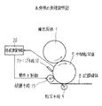
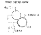
図1は本発明の原理説明図である。図において、1は像形成体、8は記録媒体、5は像形成体1に形成されたトナー像を一次転写する中間転写体、9は中間転写体5に一次転写されたトナー像を記録媒体8に二次転写する転写手段、10は転写手段9による二次転写後に、中間転写体5の面をクリーニングするクリーニング手段、15は中間転写体5の面に接触及び退避し、接触によって、中間転写体5の表面が変質して電気抵抗値が低下した変質層を研磨する研磨手段、20は少なくとも転写手段9による二次転写後に、中間転写体5の電気抵抗を測定する抵抗測定手段である。また、研磨手段15は、中間転写体5の回転方向に対して転写手段9の下流側でクリーニング手段10の上流側に設けた構成とする。
【0024】
画像形成装置において、抵抗測定手段20による測定結果に応じて研磨手段15の動作を制御するように構成されている。
従って、抵抗測定手段20によって中間転写体5の電気抵抗を測定して、抵抗値が許容限界値以下に低下したか否かにより、研磨手段15を中間転写体5に接触させて研磨するか否かを制御して、表面の変質層のために抵抗値が低下して転写性能が悪化した中間転写体5の変質層を研磨手段15の研磨によって除去し、正常な抵抗値に戻して転写性能を復旧させることができ、印刷品質を確保することができる。
【0025】
従って、研磨手段15によって削られた中間転写体5の変質層の研磨粉が研磨手段15をすり抜けても、クリーニング手段10によって残留トナーと共に除去することができる。
【0029】
【発明の実施の形態】
以下、従来例で説明した多色電子写真装置に本発明を適用した実施例1及び実施例2を図2〜図8を参照して説明する。全図を通じて同一符号は同一対象物を示す。
【0030】
1)実施例1
図2〜図7により実施例1を説明する。図2は本発明の実施例1を示す内部側面図、図3は実施例1の要部を拡大して示す説明図、図4は実施例1の制御ブロック図、図5は実施例1のフローチャート、図6は実施例1の電圧測定の説明図、図7は実施例1のタイムチャートである。
【0031】
図2に示すように、中間転写ドラム5a(中間転写体)の周辺の転写ローラ9a(転写手段)とクリーナ10Aの間に、研磨ローラ15a(研磨手段)及び研磨によって発生する研磨粉を収容する収容部150 でユニットに構成された研磨部15Aが配置されている。研磨ローラ15aは、目の細かい研磨材で形成されている。
【0032】
中間転写ドラム5aの表面の変質層は厚さ3〜5μmを越えると転写性能の低下が顕著になるので、3〜5μmを許容限度とし、中間転写ドラム5aの数回転程度で数μmの研磨ができて正常面が得られるように、研磨ローラ15aの研磨材の目の粗さ及び中間転写ドラム5aとの後述する接触圧力が設定される。
【0033】
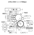
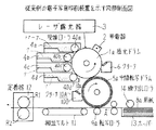
図3に示すように、研磨ローラ15aは、離接機構16によって中間転写ドラム5aに対して接触及び退避し、接触時に回転機構17によって回転する。
離接機構16は、研磨ローラ15aが駆動軸160 に固定され、駆動軸160 を一端で回動自在に支持し、中間点で支軸161 に回動自在に支持されたレバー162 が設けられている。
【0034】
レバー162 の他端はスプリング164 に付勢されて偏心カム163 に圧接し、常態では、偏心カム163 の短径がレバー162 に接触し、研磨ローラ15aは中間転写ドラム5aから退避している。偏心カム163 の軸165 にモータM1が連結している。
【0035】
また、回転機構17は、モータM2が連結する歯付きプーリ (以下プーリという)P1 、支軸161 に回動自在に支持されたプーリP2、駆動軸160 に固定されたプーリP3、プーリP1,P2 に掛けられたタイミングベルト (以下ベルトという)B1 及びプーリP2,P3 に掛けられたベルトB2で構成されている。
【0036】
従って、モータM2の駆動でプーリP1の回転がプーリP2を介してプーリP3に伝達し、研磨ローラ15aが回転する。
よって、モータM1の駆動で偏心カム163 を半回転すると偏心カム163 の長径がレバー162 を押し、レバー162 の揺動で研磨ローラ15aは中間転写ドラム5aに所定圧力で接触する。この時までにモータM2を駆動させて研磨ローラ15aを回転させれば、中間転写ドラム5aの表面が研磨ローラ15aによって研磨される。
【0037】
クリーニングブレード10a(クリーニング手段)は、図示していないプランジャーマグネット (図4参照)に連結し、常態では、先端が中間転写ドラム5aから離れており、プランジャーマグネットの励磁により先端が中間転写ドラム5aに接触する。
【0038】
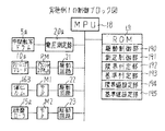
また、図4の制御ブロック図は、本発明に関係するものだけ (従って、直接印刷動作に関わるものは省いている) を示しており、図において、18はMPU、19はROM、20aは電圧測定器(抵抗測定手段)、21〜23は駆動回路を示す。
【0039】
MPU18は、ROM19に格納された制御プログラムに従って各部を制御する。
ROM19は、駆動制御部190 、測定制御部191 、限界判定部192 及び基準判定部193 のプログラムと、限界値設定部194 及び基準値設定部195 を備えている。
【0040】
駆動制御部190 は、限界判定部192 から電圧測定器20aによる測定値V1が限界値VL以下であるとの通知を受けた時に、感光ドラム1a及び中間転写ドラム5aを空回りさせて、駆動回路21を制御してクリーニングブレード10aを中間転写ドラム5aへ接触させ、同時に駆動回路22,23 を制御して研磨ローラ15aを回転させると共に中間転写ドラム5aへ接触させる。また、基準判定部193 から正常復帰、即ち、電圧測定器20aによる測定値V1が基準値Vo以上であるとの通知を受けた時に、研磨ローラ15aを中間転写ドラム5aから退避させて回転を停止させ、次いでクリーニングブレード10aを中間転写ドラム5aから退避させる。(図7参照)
また、基準判定部193 からの正常復帰の通知により研磨ローラ15aを中間転写ドラム5aから退避させると共に回転を停止させ、次いで、クリーニングブレード10aを中間転写ドラム5aから退避させる。
【0041】
測定制御部191 は、装置に電源が投入された時、定電流印加(中間転写ドラム5aの転写バイアス) での電圧測定器20aによる中間転写ドラム5aに掛かる電圧の測定を制御し、測定値V1を限界判定部192 へ送る。また、研磨ローラ15aによる研磨中に、同様に電圧測定を制御し、測定値V1を基準判定部193 へ送る。基準判定部193 から基準値Voに達した旨の通知により測定を停止する。
【0042】
限界判定部192 は、測定制御部191 から送られた測定値V1と、限界値設定部194 から読み出した限界値VLを比較し、V1>VLであれば、許容範囲内であることを測定制御部191 へ通知し、V1≦VLであれば、限界値VL以下 (中間転写ドラム5aの研磨が必要) である旨を駆動制御部190 及び測定制御部191 へ通知する。
【0043】
基準判定部193 は、測定制御部191 から送られた測定値V1と、基準値設定部195 から読み出した基準値Voを比較し、V1≧Voになった時に、基準値Voに達した旨を駆動制御部190 及び測定制御部191 へ通知する。
【0044】
限界値設定部194 は、中間転写ドラム5aの表面の限界値VLが設定されている。
電圧限界値VLは、中間転写ドラム5aの転写性能の低下の許容限界の電圧値である。
【0045】
基準値設定部195 は、中間転写ドラム5aの基準値Vo (=VL+α) が設定されている。基準値Voは、中間転写ドラム5aの正常な転写性能が得られる電圧値である。
【0046】
電圧測定器20aは、測定制御部191 に制御されて、定電流電源PWにより中間転写ドラム5aに(アルミニウムの芯金から印加)掛かる電圧を測定して、測定制御部191 に通知する。
【0047】
即ち、図6に示すように、電圧測定は定電流電源PWによって中間転写ドラム5aとアース間の電圧を測定する。元来は、中間転写ドラム5aの表面の電気抵抗Rの低下状態をチェックするために測定するのであるが、RI=V(ここで、Vは電圧、Iは電流)であり、定電流電源PWであるので、RはVに比例し、Rを計算するまでもなく、Vの低下状態からRの低下を判定することができる。
【0048】
このような構成及び機能を有するので、次に図5のフローチャート及び図7のタイムチャートにより作用を説明する。
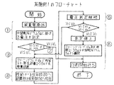
▲1▼まず、装置の電源をONすると、電圧測定器20aで中間転写ドラム5aに掛かる電圧を測定し、測定値V1を限界判定部192 へ送る。
【0049】
▲2▼限界判定部192 で測定値V1と設定された限界値VLを比較し、V1>VLであれば、印刷開始待ち状態とする。
▲3▼比較結果が、V1≦VLであれば、図7に示すように、クリーニングブレード10a及び研磨ローラ15aを中間転写ドラム5aに接触させて、残留トナーのクリーニング及び変質層の研磨を行う。
【0050】
即ち、図7(c) 及び(d) に示すように、研磨ローラ15aが回転を開始し、クリーニングブレード10aが中間転写ドラム5aに接触し、同時に(a) に示すように、偏心カム163 が1/2回転して、(b) に示すように研磨ローラ15aが中間転ドラム5aを押圧して研磨を開始する。
【0051】
▲4▼クリーニングされた残留トナーはクリーナ10Aの収容部100 に収容され、研磨で発生した研磨粉は研摩部15Aの収容部150 へ収容される。
▲5▼研磨の進行中、電圧測定器20aにより電圧測定を継続して行い、測定値V1を基準判定部193 へ送る。
【0052】
▲6▼基準判定部193 で測定値V1と設定された基準値Voを比較し、V1≧Voとなった時に、測定を停止し、図7に示すように、クリーニングブレード10a及び研磨ローラ15aを中間転写ドラム5aから離間し、印刷開始待ち状態となる。
【0053】
即ち、図7(a) 〜(c) に示すように、偏心カム163 を1/2回転を開始すると同時に研磨ローラ15aを中間転写ドラム5aから離間し、(a) 及び(d) に示すように、偏心カム163 の1/2回転が終了したタイミングでクリーニングブレード10aを中間転写ドラム5aから離間する。
【0054】
このようにして、中間転写ドラム5aの表面が変質して電気抵抗が低下するのを電圧測定器20aによって測定し、測定値が許容限界値以下に低下した時に、研磨ローラ15aで研磨して変質層を除去することができるので、転写性能の低下により色が薄くなること、特にカラー印刷における色変わりを防止し、印刷品質を向上させることができる。しかも、中間転写ドラム5aの導電性フィルム51を研磨によって転写性能を復旧させて有効に使用することができる。
【0055】
また、中間転写ドラム5aの回転方向に対してクリーナ10Aの下流側に研磨部15Aを配置したので、研磨粉が研磨ローラ15aをすり抜けても、研磨粉をクリーニングブレード10aで除去できて、中間転写ドラム5a上から除くことができるので、画質の劣化を防止することができる。
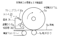
2)実施例2
図8により実施例2を説明する。実施例2が上記実施例1と異なるのは、実施例1のクリーナ10Aと研磨部15Aを纏めて1つのユニットに構成し、収容部100,150 を共通化したものである。
【0056】
即ち、図8に示すように、クリーニングブレード10a及び研磨ローラ15aが1つの筺体24内に配置され、共通の収容部240 が設けられて、ユニット25に構成されている。クリーニングブレード10a及び研磨ローラ15aは、図示省略した移動機構によって筺体24を水平に移動させることにより中間転写ドラム5aに同時に離接する。研磨ローラ15aの回転機構及び制御は実施例1と同様である。
【0057】
このような構成を有するので、研磨ローラ15aを回転し、クリーニングブレード10a及び研磨ローラ15aを中間転写ドラム5aに接触させて、中間転写ドラム5aを研磨ローラ15aが研磨したときに生じた研磨粉、及びクリーニングブレード10aによってクリーニングされた残留トナーが収容部240 に収容される。
【0058】
従って、ユニット筺体及び離接機構が共通化されて部品点数が削減され、廃トナー及び研磨粉の処理が簡単になり、コストの改善及び装置の小型化を図ることができる。
【0059】
本発明では、中間転写体の表面の電気抵抗を測定して、抵抗値が所定値以下になった時に、中間転写体の表面の変質層を研磨する方法であるが、変質層の生成と印刷量の間には、近似的ながら相関があるので、所定枚数(例えば、1000〜2000枚) 印刷する毎に所定時間(或いは中間転写ドラム5aの回転回数) 研磨する方法としても相当の効果が得られる。また、印刷動作によって所定枚数で研磨を行うことができない場合には、印刷枚数に比例した時間だけ研磨する方法としても良い。
【0060】
上記実施例では、定電流電源により電圧を測定する方法を説明したが、定電圧電源により電流を測定する方法としても良いことは勿論である。
また、中間転写ドラム5aを使用した装置の場合を説明したが、中間転写ベルトを使用した装置の場合にも適用することができる。
【0061】
更に、カラー印刷を行う場合を説明したが、モノクロ印刷の場合にも中間転写体を有する装置であれば、同様に適用することができる。また、感光ドラム1aを使用した装置の場合を説明したが、感光ベルトを使用した装置の場合にも同様に適用することができる。
【0062】
【発明の効果】
以上説明したように本発明によれば、
▲1▼中間転写体の表面が変質して電気抵抗値が低下しても、変質層を除去することができて、転写性能の低下により転写トナーが薄くなることが防止でき、特にカラー印刷の場合の色の変化を防止できて、印刷品質を高めることができる。
【0063】
▲2▼中間転写体の表面の導電性フィルムを有効に使用することができる。
▲3▼中間転写体の表面を研磨した際に生じる研磨粉が、研磨手段をすり抜けてもクリーニング手段に除去されて、中間転写体上から除去することができるので、画質の劣化を防止することができる。
【0064】
▲4▼クリーニング手段の廃トナーの収容部と研磨手段の研磨粉の収容部を共通とし、また、クリーニング手段と研磨手段を共通ユニットに構成したことにより、ユニット筺体及び離接機構が共通化されて部品点数が削減され、廃トナー及び研磨粉の処理が簡単になり、コストの改善及び装置の小型化を図ることができる。という効果がある。
【図面の簡単な説明】
【図1】 本発明の原理説明図
【図2】 本発明の実施例1を示す内部側面図
【図3】 実施例1の要部を拡大して示す説明図
【図4】 実施例1の制御ブロック図
【図5】 実施例1のフローチャート
【図6】 実施例1の電圧測定の説明図
【図7】 実施例1のタイムチャート
【図8】 実施例2の要部を示す側面図
【図9】 従来例の電子写真印刷装置を示す内部側面図
【符号の説明】
1は像形成体、 1aは感光ドラム、 5は中間転写体、
5aは中間転写ドラム、 6,10Aはクリーナ、 8は記録媒体、
8aは用紙、 9は転写手段、 9aは転写ローラ、
10はクリーニング手段、10aはクリーニングブレード、
15は研磨手段、 15Aは研磨部、 15aは研磨ローラ、
20は抵抗測定手段、 20aは電圧測定器、 25はユニット、
100,150,240 は収容部[0001]
BACKGROUND OF THE INVENTION
The present invention relates to an image forming apparatus such as an electrophotographic printer, and more particularly to an image forming apparatus that controls the operation of a polishing unit in accordance with the electric resistance of the surface of an intermediate transfer member.
[0002]
In recent years, with the development of office automation, demand for character image information output devices with the advantages that plain paper can be used, low noise, high speed and high quality printing, and easy colorization. Is growing. For this reason, electrophotographic printers and electrostatic printers that form an electrostatic latent image on a photosensitive drum and develop it with a developer are provided and used in computer terminal devices, copying machines, facsimile machines, and the like.
[0003]
In such a printer that performs color printing, a plurality of developing units are arranged around the photosensitive drum, and the electrostatic latent images formed on the photosensitive drum are sequentially developed with color toners, and then temporarily transferred to an intermediate transfer. The image is transferred to a drum, and all colors are superimposed on an intermediate transfer drum and then transferred to a printing sheet.
[0004]
However, as the intermediate transfer drum is used, the transfer efficiency is lowered due to surface alteration, and the color becomes light. Especially in color printing, since the color on the drum side becomes lighter, the color changes. Therefore, it is necessary to polish the surface and remove the deteriorated layer. A method that facilitates processing is desired.
[0005]
[Prior art]
FIG. 9 illustrates an internal side view of the multicolor electrophotographic printing apparatus. As shown in the figure, around the photosensitive drum 1a rotating in the direction of the arrow, there are four developing
[0006]
The developing
[0007]
The
[0008]
Around the
[0009]
The photosensitive drum 1a and the
Next, the operation will be described. First, the photosensitive drum 1a and the
[0010]
Further, when this latent image area passes through the developing roller 40a of the developing
The first color toner image adhering to the photosensitive drum 1a is transferred (primary transfer) to the
[0011]
Thus, the second color to the fourth color are sequentially positioned with timing, exposure, development and transfer are performed, and the four color toner images are transferred onto the
[0012]
On the other hand, the printing paper (hereinafter referred to as paper) 8a is fed one by one from the hopper 13 by the feeding roller 14 and conveyed to a position in contact with the toner image transferred onto the
[0013]
After the four color toner images are transferred to the
[0014]
The paper 8a on which the toner images of four colors are transferred is sandwiched between the heat roller R1 constituting the fixing device 12 and the rubber roller R2 that is pressed against and rotates, and the toner image is fixed on the paper 8a by heat and pressure. Are sent to a stacker (not shown).
[0015]
By repeating the above operation, color printing is performed one after another.
In the above example, the case of the negative charging process has been described. However, the same process is performed for the positive charging.
[0016]
In this way, toner images of different colors are sequentially formed on the photosensitive drum 1a by the plurality of developing
[0017]
There is also an apparatus that uses a belt photoreceptor instead of the photosensitive drum 1a, and there is an apparatus that uses an intermediate transfer belt instead of the
[0018]
[Problems to be solved by the invention]
According to the conventional method, the intermediate transfer drum needs to maintain a predetermined resistance value on the surface in order to satisfy the transfer performance. However, depending on the material of the intermediate transfer drum, the surface is altered by the bias applied during transfer, and the resistance value is lowered. The depth of alteration is about several μm from the surface, but it deteriorates transfer performance such as a decrease in transfer efficiency.
[0019]
That is, the transfer toner becomes thinner due to the deterioration of the transfer performance. In particular, in color printing, there is a problem that the toner becomes thick due to the superposition of three colors or four colors, and the color toner on the intermediate transfer drum side becomes thin and the color changes.
[0020]
Regarding the problem of the surface of the intermediate transfer drum, in Japanese Patent Laid-Open No. 5-241454, a first cleaning means and a second cleaning means (PFA tube made of fluororesin is wound around sponge rubber around the intermediate transfer member) Cleaning roller), the first cleaning means removes the residual toner on the surface of the intermediate transfer drum, and the second cleaning means removes residual toner and paper dust that cannot be removed by repeated printing. Thus, for example, a method of removing every 10 sheets is described, but this method cannot be a method for solving the above problems.
[0021]
Japanese Laid-Open Patent Publication No. 2-52373 discloses the surface state of an intermediate transfer member (the generation state of a toner filming layer formed by a minute toner adhering to the surface or a toner dissolved by heat or pressure). A method of detecting by a sensor and removing it by a rubbing member has been proposed, but in this method, the increase in friction between the intermediate transfer member and the cleaner due to the generation of the toner filming layer is restored to normal, and transfer due to adhered matter is performed. This is intended to prevent the decrease in efficiency and the unstable driving due to friction, and cannot solve the above problems.
[0022]
An object of the present invention is to provide an image forming apparatus that can remove a deteriorated layer on the surface of an intermediate transfer member to prevent deterioration in transfer performance and improve print quality.
[0023]
[Means for Solving the Problems]
FIG. 1 is a diagram illustrating the principle of the present invention. In the figure, 1 is an image forming body, 8 is a recording medium, 5 is an intermediate transfer body that primarily transfers a toner image formed on the image forming body 1, and 9 is a recording medium that is primarily transferred to the
[0024]
The image forming apparatus is configured to control the operation of the polishing unit 15 in accordance with the measurement result by the
Therefore, whether or not the polishing means 15 is brought into contact with the
[0025]
What follow, even abrasive powder deteriorated layer of the
[0029]
DETAILED DESCRIPTION OF THE INVENTION
Embodiments 1 and 2 in which the present invention is applied to the multicolor electrophotographic apparatus described in the conventional example will be described below with reference to FIGS. The same reference numerals denote the same objects throughout the drawings.
[0030]
1) Example 1
A first embodiment will be described with reference to FIGS. 2 is an internal side view showing the first embodiment of the present invention, FIG. 3 is an explanatory diagram showing an enlarged main part of the first embodiment, FIG. 4 is a control block diagram of the first embodiment, and FIG. FIG. 6 is an explanatory diagram of voltage measurement according to the first embodiment, and FIG. 7 is a time chart according to the first embodiment.
[0031]
As shown in FIG. 2, a polishing
[0032]
When the thickness of the deteriorated layer on the surface of the
[0033]
As shown in FIG. 3, the polishing
The separation / contact mechanism 16 includes a polishing
[0034]
The other end of the lever 162 is urged by the spring 164 and presses against the
[0035]
The rotation mechanism 17 includes a toothed pulley (hereinafter referred to as a pulley) P1 connected to the motor M2, a pulley P2 rotatably supported on a support shaft 161, a pulley P3 fixed to a drive shaft 160, and pulleys P1 and P2. A timing belt (hereinafter referred to as a belt) B1 hung on the belt B1 and a belt B2 hung on the pulleys P2 and P3.
[0036]
Accordingly, the rotation of the pulley P1 is transmitted to the pulley P3 via the pulley P2 by driving the motor M2, and the polishing
Therefore, when the
[0037]
The cleaning blade 10a (cleaning means) is connected to a plunger magnet (not shown) (see FIG. 4). Normally, the tip is separated from the
[0038]
Further, the control block diagram of FIG. 4 shows only those related to the present invention (therefore, those relating to the direct printing operation are omitted). In the figure, 18 is MPU, 19 is ROM, and 20a is voltage. Measuring devices (resistance measuring means), 21 to 23 indicate drive circuits.
[0039]
The MPU 18 controls each unit in accordance with a control program stored in the ROM 19.
The ROM 19 includes a
[0040]
When the
In addition, the polishing
[0041]
The
[0042]
The
[0043]
The
[0044]
The limit value setting unit 194 sets the limit value VL of the surface of the
The voltage limit value VL is a voltage value that is an allowable limit for a decrease in transfer performance of the
[0045]
The reference value setting unit 195 sets a reference value Vo (= VL + α) for the
[0046]
The voltage measuring device 20a is controlled by the
[0047]
That is, as shown in FIG. 6, the voltage is measured by measuring the voltage between the
[0048]
Since it has such a configuration and function, the operation will be described with reference to the flowchart of FIG. 5 and the time chart of FIG.
{Circle around (1)} First, when the apparatus is turned on, the voltage applied to the
[0049]
(2) The
(3) If the comparison result is V1 ≦ VL, as shown in FIG. 7, the cleaning blade 10a and the polishing
[0050]
That is, as shown in FIGS. 7C and 7D, the polishing
[0051]
(4) The cleaned residual toner is accommodated in the
(5) While the polishing is in progress, voltage measurement is continuously performed by the voltage measuring instrument 20a, and the measured value V1 is sent to the
[0052]
(6) The
[0053]
That is, as shown in FIGS. 7 (a) to 7 (c), the
[0054]
In this way, the voltage measuring device 20a measures that the surface of the
[0055]
Further, since the polishing portion 15A is disposed on the downstream side of the cleaner 10A with respect to the rotation direction of the
2) Example 2
A second embodiment will be described with reference to FIG. The second embodiment is different from the first embodiment in that the cleaner 10A and the polishing portion 15A of the first embodiment are combined into one unit and the
[0056]
That is, as shown in FIG. 8, the cleaning blade 10 a and the polishing
[0057]
Since it has such a configuration, the polishing
[0058]
Therefore, the unit housing and the separation / contact mechanism are made common, the number of parts is reduced, the processing of the waste toner and the abrasive powder is simplified, the cost can be improved, and the apparatus can be downsized.
[0059]
In the present invention, the electrical resistance of the surface of the intermediate transfer member is measured, and the deteriorated layer on the surface of the intermediate transfer member is polished when the resistance value becomes a predetermined value or less. Since there is an approximate correlation between the amounts, a considerable effect can be obtained as a method of polishing for a predetermined time (or the number of rotations of the
[0060]
In the above embodiment, the method of measuring the voltage with the constant current power source has been described, but it is needless to say that the method of measuring the current with the constant voltage power source may be used.
Further, the case of the apparatus using the
[0061]
Furthermore, although the case of performing color printing has been described, the present invention can be similarly applied to monochrome printing as long as the apparatus has an intermediate transfer member. Further, the case of the apparatus using the photosensitive drum 1a has been described, but the same can be applied to the case of an apparatus using the photosensitive belt.
[0062]
【The invention's effect】
As described above, according to the present invention,
(1) Even if the surface of the intermediate transfer member changes in quality and the electric resistance value decreases, the deteriorated layer can be removed and the transfer toner can be prevented from being thinned due to a decrease in transfer performance. In this case, the color change can be prevented and the print quality can be improved.
[0063]
(2) The conductive film on the surface of the intermediate transfer member can be used effectively.
(3) Since the polishing powder generated when the surface of the intermediate transfer member is polished can be removed from the intermediate transfer member by being removed by the cleaning unit even if it passes through the polishing unit, the deterioration of the image quality can be prevented. Can do.
[0064]
(4) The waste toner storage part of the cleaning means and the polishing powder storage part of the polishing means are made common, and the cleaning means and polishing means are configured in a common unit, so that the unit housing and the separation / contact mechanism are made common. Thus, the number of parts can be reduced, waste toner and polishing powder can be easily processed, cost can be improved, and the apparatus can be downsized. There is an effect.
[Brief description of the drawings]
FIG. 1 is a diagram illustrating the principle of the present invention. FIG. 2 is an internal side view showing a first embodiment of the present invention. FIG. 3 is an explanatory diagram showing an enlarged main part of the first embodiment. Control block diagram [FIG. 5] Flow chart of embodiment 1 [FIG. 6] Explanatory diagram of voltage measurement of embodiment 1 [FIG. 7] Time chart of embodiment 1 [FIG. 8] Side view showing essential parts of embodiment 2 [FIG. FIG. 9 is an internal side view showing a conventional electrophotographic printing apparatus.
1 is an image forming member, 1a is a photosensitive drum, 5 is an intermediate transfer member,
5a is an intermediate transfer drum, 6,10A is a cleaner, 8 is a recording medium,
8a is paper, 9 is transfer means, 9a is transfer roller,
10 is a cleaning means, 10a is a cleaning blade,
15 is a polishing means, 15A is a polishing section, 15a is a polishing roller,
20 is a resistance measuring means, 20a is a voltage measuring device, 25 is a unit,
100,150,240 is the accommodating part
Claims (1)
Priority Applications (1)
| Application Number | Priority Date | Filing Date | Title |
|---|---|---|---|
| JP27308795A JP3684635B2 (en) | 1995-10-20 | 1995-10-20 | Image forming apparatus |
Applications Claiming Priority (1)
| Application Number | Priority Date | Filing Date | Title |
|---|---|---|---|
| JP27308795A JP3684635B2 (en) | 1995-10-20 | 1995-10-20 | Image forming apparatus |
Publications (2)
| Publication Number | Publication Date |
|---|---|
| JPH09114269A JPH09114269A (en) | 1997-05-02 |
| JP3684635B2 true JP3684635B2 (en) | 2005-08-17 |
Family
ID=17522968
Family Applications (1)
| Application Number | Title | Priority Date | Filing Date |
|---|---|---|---|
| JP27308795A Expired - Fee Related JP3684635B2 (en) | 1995-10-20 | 1995-10-20 | Image forming apparatus |
Country Status (1)
| Country | Link |
|---|---|
| JP (1) | JP3684635B2 (en) |
Families Citing this family (9)
| Publication number | Priority date | Publication date | Assignee | Title |
|---|---|---|---|---|
| JP2933602B1 (en) * | 1998-04-14 | 1999-08-16 | 新潟日本電気株式会社 | Image forming device |
| KR20000024728A (en) * | 1998-10-01 | 2000-05-06 | 윤종용 | Device for cleaning roller of electrophotographic type printer |
| JP4310020B2 (en) * | 1999-03-31 | 2009-08-05 | キヤノン株式会社 | Image forming apparatus |
| JP3605007B2 (en) * | 1999-07-16 | 2004-12-22 | キヤノン株式会社 | Image forming device |
| JP3248523B2 (en) | 1999-07-22 | 2002-01-21 | 新潟富士ゼロックス製造株式会社 | Transfer fixing device for electrophotographic image forming apparatus |
| JP5387945B2 (en) * | 2008-11-12 | 2014-01-15 | 株式会社リコー | Image forming apparatus |
| JP5750912B2 (en) * | 2011-01-28 | 2015-07-22 | 富士ゼロックス株式会社 | Image forming apparatus |
| JP2014021205A (en) * | 2012-07-13 | 2014-02-03 | Ricoh Co Ltd | Fixing device and image forming apparatus |
| JP2015106134A (en) * | 2013-12-02 | 2015-06-08 | 富士ゼロックス株式会社 | Image forming apparatus |
-
1995
- 1995-10-20 JP JP27308795A patent/JP3684635B2/en not_active Expired - Fee Related
Also Published As
| Publication number | Publication date |
|---|---|
| JPH09114269A (en) | 1997-05-02 |
Similar Documents
| Publication | Publication Date | Title |
|---|---|---|
| EP0579499B1 (en) | An image forming apparatus comprising a charging member | |
| US6990309B2 (en) | Method and apparatus for image forming performing improved cleaning and discharging operation on image forming associated members | |
| JP4966043B2 (en) | Image forming apparatus | |
| US6341205B1 (en) | Image forming apparatus with cleaning bias feature | |
| US7751752B2 (en) | Image forming apparatus | |
| JP3684635B2 (en) | Image forming apparatus | |
| JP4684617B2 (en) | Image forming apparatus | |
| JPH11194690A (en) | Image forming device | |
| JPH0895317A (en) | Image forming device | |
| JP3203974B2 (en) | Image forming device | |
| US6912369B2 (en) | Image forming apparatus | |
| JP4842399B2 (en) | Image forming method and apparatus | |
| JP6335664B2 (en) | Image forming apparatus | |
| JP2011095557A (en) | Image forming method and image forming apparatus | |
| JP2005099781A (en) | Image forming method and apparatus | |
| JP3576761B2 (en) | Image forming device | |
| JP4054536B2 (en) | Image forming apparatus | |
| JPH08110709A (en) | Image forming device | |
| JP7215279B2 (en) | image forming device | |
| JP2003345106A (en) | Image forming apparatus | |
| JP7140553B2 (en) | image forming device | |
| JPH10274891A (en) | Image forming device | |
| JP2002258613A (en) | Image forming device | |
| JP2006267549A (en) | Image forming apparatus | |
| JPH09179459A (en) | Image forming device |
Legal Events
| Date | Code | Title | Description |
|---|---|---|---|
| A131 | Notification of reasons for refusal |
Free format text: JAPANESE INTERMEDIATE CODE: A131 Effective date: 20040907 |
|
| A521 | Request for written amendment filed |
Free format text: JAPANESE INTERMEDIATE CODE: A523 Effective date: 20041105 |
|
| A131 | Notification of reasons for refusal |
Free format text: JAPANESE INTERMEDIATE CODE: A131 Effective date: 20041124 |
|
| A521 | Request for written amendment filed |
Free format text: JAPANESE INTERMEDIATE CODE: A523 Effective date: 20050121 |
|
| TRDD | Decision of grant or rejection written | ||
| A01 | Written decision to grant a patent or to grant a registration (utility model) |
Free format text: JAPANESE INTERMEDIATE CODE: A01 Effective date: 20050510 |
|
| A61 | First payment of annual fees (during grant procedure) |
Free format text: JAPANESE INTERMEDIATE CODE: A61 Effective date: 20050523 |
|
| R150 | Certificate of patent or registration of utility model |
Free format text: JAPANESE INTERMEDIATE CODE: R150 |
|
| FPAY | Renewal fee payment (event date is renewal date of database) |
Free format text: PAYMENT UNTIL: 20090610 Year of fee payment: 4 |
|
| FPAY | Renewal fee payment (event date is renewal date of database) |
Free format text: PAYMENT UNTIL: 20100610 Year of fee payment: 5 |
|
| FPAY | Renewal fee payment (event date is renewal date of database) |
Free format text: PAYMENT UNTIL: 20110610 Year of fee payment: 6 |
|
| LAPS | Cancellation because of no payment of annual fees |