JP3683531B2 - Tensioner with damping mechanism - Google Patents
Tensioner with damping mechanism Download PDFInfo
- Publication number
- JP3683531B2 JP3683531B2 JP2001547477A JP2001547477A JP3683531B2 JP 3683531 B2 JP3683531 B2 JP 3683531B2 JP 2001547477 A JP2001547477 A JP 2001547477A JP 2001547477 A JP2001547477 A JP 2001547477A JP 3683531 B2 JP3683531 B2 JP 3683531B2
- Authority
- JP
- Japan
- Prior art keywords
- pivot
- belt
- tensioner
- force component
- cylindrical member
- Prior art date
- Legal status (The legal status is an assumption and is not a legal conclusion. Google has not performed a legal analysis and makes no representation as to the accuracy of the status listed.)
- Expired - Lifetime
Links
Images


Classifications
-
- F—MECHANICAL ENGINEERING; LIGHTING; HEATING; WEAPONS; BLASTING
- F16—ENGINEERING ELEMENTS AND UNITS; GENERAL MEASURES FOR PRODUCING AND MAINTAINING EFFECTIVE FUNCTIONING OF MACHINES OR INSTALLATIONS; THERMAL INSULATION IN GENERAL
- F16H—GEARING
- F16H7/00—Gearings for conveying rotary motion by endless flexible members
- F16H7/08—Means for varying tension of belts, ropes, or chains
- F16H7/10—Means for varying tension of belts, ropes, or chains by adjusting the axis of a pulley
- F16H7/12—Means for varying tension of belts, ropes, or chains by adjusting the axis of a pulley of an idle pulley
- F16H7/1209—Means for varying tension of belts, ropes, or chains by adjusting the axis of a pulley of an idle pulley with vibration damping means
- F16H7/1218—Means for varying tension of belts, ropes, or chains by adjusting the axis of a pulley of an idle pulley with vibration damping means of the dry friction type
-
- F—MECHANICAL ENGINEERING; LIGHTING; HEATING; WEAPONS; BLASTING
- F16—ENGINEERING ELEMENTS AND UNITS; GENERAL MEASURES FOR PRODUCING AND MAINTAINING EFFECTIVE FUNCTIONING OF MACHINES OR INSTALLATIONS; THERMAL INSULATION IN GENERAL
- F16H—GEARING
- F16H7/00—Gearings for conveying rotary motion by endless flexible members
- F16H7/08—Means for varying tension of belts, ropes, or chains
- F16H2007/0802—Actuators for final output members
- F16H2007/081—Torsion springs
-
- F—MECHANICAL ENGINEERING; LIGHTING; HEATING; WEAPONS; BLASTING
- F16—ENGINEERING ELEMENTS AND UNITS; GENERAL MEASURES FOR PRODUCING AND MAINTAINING EFFECTIVE FUNCTIONING OF MACHINES OR INSTALLATIONS; THERMAL INSULATION IN GENERAL
- F16H—GEARING
- F16H7/00—Gearings for conveying rotary motion by endless flexible members
- F16H7/08—Means for varying tension of belts, ropes, or chains
- F16H7/0829—Means for varying tension of belts, ropes, or chains with vibration damping means
- F16H2007/084—Means for varying tension of belts, ropes, or chains with vibration damping means having vibration damping characteristics dependent on the moving direction of the tensioner
-
- F—MECHANICAL ENGINEERING; LIGHTING; HEATING; WEAPONS; BLASTING
- F16—ENGINEERING ELEMENTS AND UNITS; GENERAL MEASURES FOR PRODUCING AND MAINTAINING EFFECTIVE FUNCTIONING OF MACHINES OR INSTALLATIONS; THERMAL INSULATION IN GENERAL
- F16H—GEARING
- F16H7/00—Gearings for conveying rotary motion by endless flexible members
- F16H7/08—Means for varying tension of belts, ropes, or chains
- F16H2007/0889—Path of movement of the finally actuated member
- F16H2007/0893—Circular path
Abstract
Description
【0001】
(発明の背景)
本発明は、ダンピング機構を備えたテンショナを有するベルト伝動システムに関する。特に、本発明は、ベルトに係合するプーリが回転自在に取り付けられたピボットアームの位置を偏倚させる捩りスプリングを備えるテンショナに関する。ダンピング機構を備えた本発明のテンショナは、特に自動車のエンジン周りに用いられるフロントエンドアクセサリドライブのマイクロVベルトの張力を制御するのに有効である。
【0002】
機械的なテンショナは、自動車のエンジン周りに用いられるフロントエンドアクセサリドライブのベルトの張力を自動制御するために用いられる。このようなテンショナはピボットアームを有する。ピボットアームはベースに固定されたピボットの回りに回転し、回転するピボットアームの軸受面としてピボットにスリーブブッシングを用いる。多くのこのようなブッシングはプラスチックから作られており、テンショナの余命をもたせるために用いられる。捩りスプリングは多くの場合、ピボットアームの位置を偏倚させ、取り付けられたプーリがベルトに当接して配置されるように、一方の端がピボットアームに連結されており、他方の端がベースに連結されている。スプリングは、ダンピング手段に働く弾性力を発生させるためにも用いられ、ダンピング手段は、ピボットアームの遥動を抑制あるいは減衰させるために、摩擦摺動面に対する垂直力成分を発生させる。
【0003】
このようなテンショナの1つがアメリカ合衆国特許第4,473,362号に開示されている。‘362のテンショナはオフセット円筒部材に取り付けられたピボットアームを備え、このオフセット円筒部材はピボットアームを支持するとともにベースに固定されたピボットの回りに回動する。たった1つの捩りスプリングが、一方の端がピボットアームに連結され、他方の端がベースに連結された状態で用いられる。ピボットに設けられた単一のスリーブ型のブッシングは、円筒部材を支える軸受面を備える。プーリベアリングのラジアル面はスリーブ型のブッシングに対して片寄っており、ブッシングにより担われるべき荷重としてモーメントすなわち偶力をもたらす。このようなテンショナは、プーリのその支持部材あるいはベースに対する片寄った構造から、しばしば「Z」型テンショナと呼ばれる。ブッシングの軸受面にもたらされた不均一な圧力荷重は、過度のブッシングの摩滅と、これに付随するプーリのミスアライメントをもたらす可能性がある。
【0004】
このようなZ型テンショナを適用した伝動システムのベルトは、プーリと係合してプーリでベルト力を発生し、このベルト力は円筒部材に伝達される(以下ハブ荷重)。‘362号の特許で説明されているように、ブッシングに対する不均一な荷重は、ハブ荷重と略同じ方向にかかる垂直力成分を発生するダンピング手段により低減される。このような力の成分をもつベルト力の指向性は、ブッシング荷重と付随する摩滅の問題の幾つかを確かに軽減する。しかし、これはあるベルト駆動状態では十分ではない。何故ならば、ダンピング手段の垂直力成分は、ある場合には、ハブ荷重を担う円筒部材に対して片寄っているベルト力により生じるモーメントとバランスをとるには十分でないからである。そして単一のブッシングは、ピボットアームが時計回り、反時計回りに搖動して軸受圧力荷重が変化することにより「べベル(bevel)」あるいは「クラウン(crown)」となる傾向がある。
【0005】
単一のブッシングにおける「べベル」あるいは「クラウン」を解決するベルトテンショナのデザインは、アメリカ合衆国特許第5,647,813号に開示されている。‘813号の特許に説明されているように、ハブ荷重とダンピング機構により発生される垂直力成分は、軸方向に離間した2つの軸受面を有する少なくとも1つあるいは2つのブッシングにより担われる。しかしながら、‘813号のテンショナはブッシングの摩滅を解消するのには好適なデザインであるものの、少なくとも2つの軸方向に離間した軸受面を用いることは、テンショナ全体の大きさや、重量、価格を増大する。更に、ハブ荷重とダンピング機構により発生される垂直力成分は、ブッシングに対して合成荷重を生じ、この合成荷重は大きすぎる可能性があり、過度のピボットブッシングの摩滅を起こす可能性がある。
【0006】
(発明の要約)
本発明によれば、特に自動車の応用分野で用いられるマイクロVフロントエンドアクセサリベルト伝動システムにおいて好適なテンショナが提供される。この分野では、テンショナの寿命を通して最高のプーリアライメントを実現するために、最高のバランシングと最小のピボットブッシングの摩滅と組み合わされた最小のテンショナ容積が重要である。本発明のベルトテンショナはベースを有する形式のものである。ピボットアームは、円筒部材に取り付けられており、円筒部材はピボットアームを支持するとともに、ベースに固定されたピボットの回りに回転する。少なくとも1つのスリーブ型ブッシングがピボットに設けられ、円筒部材を支持する軸受面を有する。プーリは、ピボットアームにベルトと係合するために取り付けられており、ベルト荷重を受ける。ベルト荷重は円筒部材に伝達されるベルト力成分を発生する(ハブ荷重)。一方の端がベースに連結され、他方の端がダンピング手段に連結された捩りスプリングは、ベルト力成分と反対方向にかかるダンピング力成分を発生する。ダンピング手段は、実質的にピボットアームとブッシングの間にピボットと平行な面に沿って取り付けられる。
【0007】
本発明の有利な点は、ハブ荷重がより効果的に実質的にピボットブッシングのより小さい荷重とバランスを取ることができ、それにより耐久性が向上されることにある。本発明の別の有利な点は、ブッシングに担われる圧力を増大させないブッシングの小型化であり、それによりテンショナ全体の容積と価格を低減することである。
【0008】
本発明のこれらの目的や他の目的、あるいは利点に関しては図面とそれについての説明を一読した後に明らかとなる。
【0009】
(発明の好ましい実施形態の説明)
図1及び図2を参照すると、プーリ12を有するテンショナ10がベルト16と幾つかのプーリを備えるベルト伝動システムの構成要素として描かれている。例えば、ベルト16はクランクプーリ18、ファン/ウオータポンププーリ20、パワーステアリングプーリ22、オルタネータプーリ24、アイドラプーリ26、テンショナプーリ12の回りに掛け回されている。テンショナプーリ12はベルト16に係合し、ベルト張力を調節するためにプーリがどのように運動するかを模式的に表わすために幾つかの位置に示されている。テンショナプーリ12はベルト16に係合し、隣接するベルトスパン28、30のベルト張力T1、T2という形でベルト荷重を受ける。ベルト張力T1、T2(すなわち荷重)は合成され、ベルトスパン28、30の間に形成される角度、あるいは二等分線に沿ってベルト力成分BFを生成する。ベルト力成分は、テンショナのピボット32対して軸方向に片寄っており、力とモーメントを含む複雑なハブ荷重を発生し、これは矢印HLで象徴的(すなわち、非具体的)に表わされている。
【0010】
図2〜図4を参照すると、テンショナ10は機械式であり、ベース42、捩りスプリング44と、シャフト64に設けられたボールベアリング62によりピボットアーム52に回転自在に取り付けられたプーリ12を備えている。ボールベアリング62は、シャフト64にフランジ付ファスナ66により保持されている。ピボットアーム52は円筒部材53に取り付けられており、円筒部材はピボットアーム52を支持するとともにピボットシャフト55の回りに回動する。少なくとも1つのスリーブ型ブッシング56がピボット32に配置されている。ピボットブッシング56は好ましくはポリメリックタイプ(polymeric type)からなり、ピボットシャフト55に対して回転するようにピボットに配置され、それによりピボットアーム52を支持する。1つのピボットブッシング56が示されているが、1つ以上のピボットブッシングを有することも可能である。ファスナ60を備えるピボットシャフト55は、円筒部材53のフランジ付穿孔57とピボットブッシング56を通って延在し、それによりピボットアーム52はベース42に取り付けられる。
【0011】
例示されたダンピング手段51は、アメリカ合衆国特許第5,647,813号に開示された形式の典型例であり、この開示内容は参照として本明細書に組み込まれる。ダンピング手段51の機構は、スプリング端部48の延長部78、ブレーキシュー70を具備し、ブレーキシュー70は、ベース42の相補的な内側弧状面74に係合する外側弧状摩擦面72を有する。ブレーキシュー70は、頂角Aで挟まれる空間を隔てて反対側を向いている内側ランプ面86、88を有する。
【0012】
ダンピング手段51に連結するスプリングの端部48は、ピボットアーム52に形成、あるいはピボットアーム52に取り付けられた突出部96の回りに曲げられている。スプリング端部の延長部78は、ブレーキシュー70から形成された内側ランプ面86と摺動自在に係合する面98を備える。ピボットアーム52は、ピボットアーム52に形成された、あるいはピボットアーム52に取り付けられた突起部100を有し、突起部100は、ブレーキシュー70から形成されたランプ面88に摺動自在に係合する相補的なランプ面102を有する。
【0013】
ダンピング手段51は、実質的にプーリ12とピボットブッシング56の間にピボット32と平行な面に沿って取り付けられる。
【0014】
ピボットアーム52の円筒部材53は、ベース42と同軸であり、ベース42と共に捩りスプリング44とダンピング手段51のためのハウジングを提供する。ピボットアーム52はベース42の第1の端部43を超えて延びている。ある応用においては、ダストシール(不図示)がスプリング44とダンピング手段51のためのクリーンな環境を維持するために用いられるかもしれない。
【0015】
図5を参照して、作動時、ベルト16と係合するためにピボットアーム52に取り付けられたプーリ12は、円筒部材に伝達されるベルト力成分を生じるベルト荷重を受ける(ハブ荷重HL)。ベース42に連結された一方の端46とダンピング手段51に連結された他方の端48とを有する捩りスプリング44は、ベルト力成分とは反対方向に作用するダンピング力DF成分を生む。図示はされていないが、一方の端46が、代わりにアーム52に連結され、他方の端48がダンピング手段51に連結されてもよいことは無論である。ハブ荷重HLとダンピング力DFは、ベース42に対し反作用力を生じ、軸受面を有するブッシング56によって担われ、例えばRFによって表される。ダンピング手段51が実質的にプーリ12とブッシング56との間にピボット32と平行な面に沿って取り付けられていることから、反作用力は実質的にブッシング56の軸受面において作用する。
【図面の簡単な説明】
【図1】 本発明のベルトテンショナを有するフロントエンドアクセサリ駆動システムの模式的な正面図である。
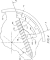
【図2】 テンショナと協働する様々な成分の力が描かれた図1の主に線2における模式的な拡大部分図である。
【図3】 4分の1の断面で示されたプーリを除いた図2の線3−3に沿った横断面図である。
【図4】 主に図3の線4−4に沿った拡大露出図であり、本発明のダンピング機構を示している。
【図5】 図2の線3−3に沿った概略図であり、本発明に係る力の要素を表わすためにプーリが取り外されている。[0001]
(Background of the Invention)
The present invention relates to a belt transmission system having a tensioner provided with a damping mechanism. In particular, the present invention relates to a tensioner including a torsion spring that biases the position of a pivot arm to which a pulley that engages a belt is rotatably attached. The tensioner of the present invention having a damping mechanism is particularly effective for controlling the tension of a micro V belt of a front end accessory drive used around an automobile engine.
[0002]
The mechanical tensioner is used to automatically control the belt tension of the front end accessory drive used around the vehicle engine. Such a tensioner has a pivot arm. The pivot arm rotates about a pivot fixed to the base, and a sleeve bushing is used for the pivot as a bearing surface of the rotating pivot arm. Many such bushings are made of plastic and are used to give the tensioner a life expectancy. The torsion springs often deviate the position of the pivot arm so that one end is connected to the pivot arm and the other end is connected to the base so that the attached pulley is placed against the belt Has been. The spring is also used to generate an elastic force acting on the damping means, and the damping means generates a normal force component with respect to the friction sliding surface in order to suppress or attenuate the pivot arm swinging.
[0003]
One such tensioner is disclosed in US Pat. No. 4,473,362. The '362 tensioner includes a pivot arm attached to an offset cylindrical member that supports the pivot arm and pivots about a pivot secured to the base. Only one torsion spring is used with one end connected to the pivot arm and the other end connected to the base. A single sleeve type bushing provided on the pivot includes a bearing surface that supports the cylindrical member. The radial surface of the pulley bearing is offset with respect to the sleeve-type bushing and provides a moment or couple as a load to be carried by the bushing. Such tensioners are often referred to as “Z” type tensioners because of the offset structure of the pulley relative to its support member or base. Non-uniform pressure loads introduced to the bushing bearing surface can result in excessive bushing wear and associated pulley misalignment.
[0004]
A belt of a transmission system to which such a Z-type tensioner is applied engages with a pulley to generate a belt force by the pulley, and this belt force is transmitted to a cylindrical member (hereinafter referred to as a hub load). As explained in the '362 patent, the non-uniform load on the bushing is reduced by a damping means that generates a normal force component in substantially the same direction as the hub load. The directivity of the belt force with such a force component will certainly alleviate some of the bushing loads and attendant wear problems. However, this is not sufficient for certain belt drive conditions. This is because the normal force component of the damping means is in some cases not sufficient to balance the moment generated by the belt force biased against the cylindrical member carrying the hub load. A single bushing tends to be "bevel" or "crown" as the pivot arm swings clockwise and counterclockwise to change the bearing pressure load.
[0005]
A belt tensioner design that solves a “bevel” or “crown” in a single bushing is disclosed in US Pat. No. 5,647,813. As described in the '813 patent, the normal force component generated by the hub load and damping mechanism is carried by at least one or two bushings having two axially spaced bearing surfaces. However, while the '813 tensioner is a good design to eliminate bushing wear, the use of at least two axially spaced bearing surfaces increases the overall size, weight, and cost of the tensioner. To do. In addition, the normal force component generated by the hub load and the damping mechanism creates a combined load on the bushing, which can be too great and can cause excessive pivot bushing wear.
[0006]
(Summary of the Invention)
According to the present invention, a tensioner suitable for a micro V front-end accessory belt transmission system used particularly in an automotive application field is provided. In this area, the minimum tensioner volume combined with the highest balancing and the lowest pivot bushing wear is important to achieve the best pulley alignment throughout the life of the tensioner. The belt tensioner of the present invention is of the type having a base. The pivot arm is attached to a cylindrical member, and the cylindrical member supports the pivot arm and rotates around a pivot fixed to the base. At least one sleeve-type bushing is provided on the pivot and has a bearing surface that supports the cylindrical member. The pulley is attached to the pivot arm to engage the belt and receives a belt load. The belt load generates a belt force component transmitted to the cylindrical member (hub load). A torsion spring having one end connected to the base and the other end connected to the damping means generates a damping force component in a direction opposite to the belt force component. The damping means is mounted along a plane substantially parallel to the pivot between the pivot arm and the bushing.
[0007]
An advantage of the present invention is that the hub load can be more effectively balanced with a substantially smaller load on the pivot bushing, thereby improving durability. Another advantage of the present invention is the downsizing of the bushing which does not increase the pressure on the bushing, thereby reducing the overall volume and cost of the tensioner.
[0008]
These and other objects or advantages of the present invention will become apparent after reading the drawings and descriptions thereof.
[0009]
(Description of Preferred Embodiment of the Invention)
1 and 2, a
[0010]
2 to 4, the
[0011]
The illustrated damping
[0012]
The
[0013]
The damping means 51 is mounted between the
[0014]
The
[0015]
Referring to FIG. 5, in operation,
[Brief description of the drawings]
FIG. 1 is a schematic front view of a front end accessory drive system having a belt tensioner of the present invention.
2 is a schematic enlarged partial view mainly at line 2 of FIG. 1 depicting the forces of the various components cooperating with the tensioner.
3 is a cross-sectional view taken along line 3-3 of FIG. 2 excluding the pulley shown in a quarter cross section.
4 is an enlarged exposure view mainly along line 4-4 of FIG. 3, showing the damping mechanism of the present invention.
FIG. 5 is a schematic view taken along line 3-3 of FIG. 2, with the pulley removed to represent the force component according to the present invention.
Claims (7)
ベースと;
円筒部材に取り付けられたピボットアームとを具備し、前記円筒部材が前記ピボットアームを支持するとともに前記ベースに固定されたピボットの回りに回転し;
更に、前記円筒部材を支持する軸受面を有し、前記ピボットに設けられた少なくとも1つのスリーブ型ブッシングと;
前記ベルトに係合するために前記ピボットアームに取り付けられ、ベルト荷重を受けるプーリと;
前記ピボットアームにより前記円筒部材に伝達されるベルト力成分とは逆向きに作用するダンピング力成分を生成するダンピング手段に一方の端が連結された捩りスプリングとを備え、
前記ダンピング力成分と前記ベルト力成分が、実質的に前記軸受面に作用する反作用力を生じることを特徴とするテンショナ。A tensioner for applying tension to the transmission belt,
With the base;
A pivot arm attached to the cylindrical member, wherein the cylindrical member supports the pivot arm and rotates about a pivot fixed to the base;
And at least one sleeve-type bushing provided on the pivot, the bearing surface supporting the cylindrical member;
A pulley attached to the pivot arm for engaging the belt and receiving a belt load;
E Bei and said torsion spring having one end in the damping means that generates a damping force component acting in the opposite direction to the belt force component transmitted to the cylindrical member by a pivot arm is connected,
The tensioner, wherein the damping force component and the belt force component generate a reaction force that substantially acts on the bearing surface.
Applications Claiming Priority (3)
| Application Number | Priority Date | Filing Date | Title |
|---|---|---|---|
| US09/469,052 US6565468B2 (en) | 1999-12-21 | 1999-12-21 | Tensioner with damping mechanism |
| US09/469,052 | 1999-12-21 | ||
| PCT/US2000/033939 WO2001046603A1 (en) | 1999-12-21 | 2000-12-13 | Tensioner with damping mechanism |
Publications (2)
| Publication Number | Publication Date |
|---|---|
| JP2003522908A JP2003522908A (en) | 2003-07-29 |
| JP3683531B2 true JP3683531B2 (en) | 2005-08-17 |
Family
ID=23862238
Family Applications (1)
| Application Number | Title | Priority Date | Filing Date |
|---|---|---|---|
| JP2001547477A Expired - Lifetime JP3683531B2 (en) | 1999-12-21 | 2000-12-13 | Tensioner with damping mechanism |
Country Status (15)
| Country | Link |
|---|---|
| US (1) | US6565468B2 (en) |
| EP (1) | EP1242756B1 (en) |
| JP (1) | JP3683531B2 (en) |
| KR (1) | KR100454785B1 (en) |
| CN (1) | CN1322253C (en) |
| AT (1) | ATE282784T1 (en) |
| AU (1) | AU764731B2 (en) |
| BR (1) | BR0016492A (en) |
| CA (1) | CA2394531C (en) |
| CZ (1) | CZ20022209A3 (en) |
| DE (1) | DE60016031T2 (en) |
| ES (1) | ES2231300T3 (en) |
| HK (1) | HK1046948B (en) |
| PL (1) | PL364883A1 (en) |
| WO (1) | WO2001046603A1 (en) |
Families Citing this family (43)
| Publication number | Priority date | Publication date | Assignee | Title |
|---|---|---|---|---|
| US6604158B1 (en) * | 1999-03-11 | 2003-08-05 | Realtime Data, Llc | System and methods for accelerated data storage and retrieval |
| US7186196B2 (en) * | 2002-07-18 | 2007-03-06 | Dayco Products, Llc | Belt tensioner with integral damping |
| US7837582B2 (en) * | 2002-09-30 | 2010-11-23 | Fenner, Inc. | Bi-directional belt tensioner |
| US7883436B2 (en) * | 2004-09-15 | 2011-02-08 | Fenner U.S., Inc. | Bi-directional tensioner |
| US6855079B2 (en) * | 2002-09-30 | 2005-02-15 | Fenner, Inc. | Bi-directional belt tensioner |
| DE102004047422A1 (en) * | 2004-09-28 | 2006-04-13 | Muhr Und Bender Kg | Belt tensioning device with high damping |
| US8075433B2 (en) | 2005-06-28 | 2011-12-13 | Dayco Products, Llc | Belt tensioner with damping member |
| DE102005052453A1 (en) * | 2005-11-03 | 2007-05-10 | Schaeffler Kg | Clamping device for a traction means, in particular a belt |
| DE102006017287B4 (en) * | 2006-04-12 | 2021-03-25 | Litens Automotive Gmbh | Tensioner for an endless drive |
| DE102006023565A1 (en) * | 2006-05-19 | 2007-11-22 | Schaeffler Kg | Clamping device for a traction means, in particular a belt or a chain |
| DE102006042105A1 (en) * | 2006-09-07 | 2008-03-27 | Schaeffler Kg | Clamping device for a traction mechanism drive |
| US20080119310A1 (en) * | 2006-11-16 | 2008-05-22 | Holcombe C Scott | Rotary tensioner |
| DE102006059550A1 (en) * | 2006-12-16 | 2008-06-19 | Schaeffler Kg | Clamping device for a traction mechanism drive |
| DE102007015676A1 (en) * | 2007-03-31 | 2008-10-02 | Schaeffler Kg | Clamping device of a traction mechanism drive |
| BRPI0810603B1 (en) * | 2007-05-01 | 2019-02-12 | Litens Automotive Partnership | TENSOR FOR TRACING A FLEXIBLE DRIVE |
| DE102007031294A1 (en) * | 2007-07-05 | 2009-01-08 | Schaeffler Kg | Clamping device for traction mechanism drives |
| DE102007031298A1 (en) * | 2007-07-05 | 2009-01-08 | Schaeffler Kg | Damping device of a mechanical tensioning system for a traction mechanism drive |
| DE102008014325A1 (en) | 2008-03-14 | 2009-09-17 | Schaeffler Kg | Belt tensioner for motor vehicle, has torsion spring formed as coil spring whose end center spaced to swivel bearing plane so that tilting torques of tangential spring force and resulting reaction force cancel each other around tilting axis |
| US8142315B2 (en) | 2008-04-30 | 2012-03-27 | Litens Automotive Partnership | Tensioner with hub load balancing feature |
| BRPI0920802B1 (en) | 2008-10-02 | 2019-11-05 | Litens Automotive Inc | tensioner assembly |
| CA2789018C (en) | 2009-02-04 | 2017-07-04 | Thomas M. Espinosa | Concrete anchor |
| US20100210385A1 (en) * | 2009-02-16 | 2010-08-19 | Gm Global Technology Operations, Inc. | Tensioner assembly for a rotary drive |
| DE102009013505A1 (en) | 2009-03-17 | 2010-09-23 | Schaeffler Technologies Gmbh & Co. Kg | Clamping device for traction drive of internal-combustion engine in motor vehicle, has tension pulley attached to rotatably supported clamping lever, which is attached by screw, where screw is screwed into spacer |
| DE102009014263B4 (en) * | 2009-03-20 | 2019-03-28 | Schaeffler Technologies AG & Co. KG | Traction drive with vibration damper |
| US20100261564A1 (en) * | 2009-04-13 | 2010-10-14 | Hughes Thomas E | Rotary tensioner |
| DE102009020589A1 (en) * | 2009-05-09 | 2010-11-11 | Schaeffler Technologies Gmbh & Co. Kg | Belt tensioning unit |
| US8092328B2 (en) * | 2009-06-30 | 2012-01-10 | The Gates Corporation | Dual tensioner assembly |
| US20110015017A1 (en) * | 2009-07-17 | 2011-01-20 | Alexander Serkh | Tensioner |
| US8157682B2 (en) * | 2009-07-17 | 2012-04-17 | The Gates Corporation | Tensioner |
| DE102009037498A1 (en) | 2009-08-13 | 2011-02-17 | Schaeffler Technologies Gmbh & Co. Kg | Seal with self-reinforcing sealing lip for a clamping system |
| US20110177897A1 (en) * | 2010-01-20 | 2011-07-21 | Peter Ward | Tensioner |
| DE102010019054A1 (en) * | 2010-05-03 | 2011-11-03 | Schaeffler Technologies Gmbh & Co. Kg | jig |
| US8617013B2 (en) | 2010-09-02 | 2013-12-31 | Dayco Ip Holdings, Llc | Tensioner with expanding spring for radial frictional asymmetric damping |
| US8545352B2 (en) | 2010-09-02 | 2013-10-01 | Dayco Ip Holdings, Llc | Tensioner with expanding spring for radial frictional asymmetric damping |
| US20120316018A1 (en) * | 2011-06-08 | 2012-12-13 | Peter Ward | Tensioner |
| WO2014063228A1 (en) | 2012-10-22 | 2014-05-01 | Litens Automotive Partnership | Tensioner with increased damping |
| US9394977B2 (en) | 2013-03-15 | 2016-07-19 | Dayco Ip Holdings, Llc | Tensioner with expanding spring for radial frictional asymmetric damping |
| DE112014004168T5 (en) | 2013-09-11 | 2016-06-16 | Litens Automotive Partnership | CLAMPING DEVICE WITH INCREASED CUSHIONING AND ARM-ON-BASE CUP CONFIGURATION |
| JP6162162B2 (en) * | 2014-02-18 | 2017-07-12 | 三ツ星ベルト株式会社 | Auto tensioner |
| US10203025B2 (en) * | 2014-02-28 | 2019-02-12 | Dayco Ip Holdings, Llc | Belt tensioner with supplemental force element |
| CN203770558U (en) * | 2014-03-25 | 2014-08-13 | 宁波丰茂远东橡胶有限公司 | High-damping low-attenuation tensioner for engine |
| EP2955414A1 (en) * | 2014-06-13 | 2015-12-16 | Aktiebolaget SKF | Tensioning device and method for assembling such a tensioning device |
| US9982760B2 (en) * | 2015-02-12 | 2018-05-29 | Ningbo Fengmao Far-East Rubber Co., Ltd. | Tensioner for engine with large and stable damping and minimum deflection of shaft |
Family Cites Families (25)
| Publication number | Priority date | Publication date | Assignee | Title |
|---|---|---|---|---|
| US4473362A (en) | 1981-07-08 | 1984-09-25 | Litens Automotive Inc. | Belt tensioner with variably proportional damping |
| US4583962A (en) | 1984-12-07 | 1986-04-22 | Litens Automotive Inc. | Timing belt tensioner with damped constant spring tensioning and belt tooth disegagement prevention |
| US4698049A (en) | 1986-04-11 | 1987-10-06 | Litens Automotive Inc. | Belt tensioner with frustoconical pivot bearing |
| US4689037A (en) | 1986-06-09 | 1987-08-25 | Litens Automotive, Inc. | Belt tensioning device with constant or variably proportional damping |
| US4725260A (en) | 1987-03-24 | 1988-02-16 | Litens Automotive Inc. | Belt tensioner with spring actuated band brake damping |
| US4824421A (en) | 1987-08-28 | 1989-04-25 | Litens Automotive Partnership | Belt tensioner with releasable belt load damping |
| US4816012A (en) | 1987-09-10 | 1989-03-28 | Litens Automotive Partnership | Tensioner with increased arcuate movement |
| US4886484A (en) | 1989-06-02 | 1989-12-12 | Litens Automotive Partnership | Torsional spring tensioner with stabilizer |
| US4971589A (en) | 1989-12-13 | 1990-11-20 | Dayco Products, Inc. | Belt tensioner and method of making the same |
| US4973292A (en) | 1990-01-25 | 1990-11-27 | Litens Automotive Partnership | Steel rimmed plastic pulley |
| US5139463A (en) | 1991-06-05 | 1992-08-18 | Litens Automotive Partnership | Serpentine drive with coil spring alternator connection |
| US5156573A (en) | 1991-06-05 | 1992-10-20 | Litens Automotive Partnership | Serpentine drive with coil spring-one-way clutch alternator connection |
| JP3666899B2 (en) * | 1994-03-18 | 2005-06-29 | ゲイツ・ユニッタ・アジア株式会社 | Belt tensioner |
| US5478285A (en) | 1995-01-31 | 1995-12-26 | The Gates Rubber Company | Belt tensioner with pivot bushing damping |
| US5722909A (en) | 1995-09-27 | 1998-03-03 | Litens Automotive Partnership | Series type decoupling device |
| US5632697A (en) | 1995-12-18 | 1997-05-27 | The Gates Corporation | Damping mechanism for a tensioner |
| US5647813A (en) | 1995-12-18 | 1997-07-15 | The Gates Corporation | Tensioner with damping mechanism and belt drive system |
| PL186552B1 (en) | 1996-08-21 | 2004-01-30 | Ontario Inc 730143 | Motor vehicle v-belt tensioner |
| DE19703033A1 (en) | 1997-01-29 | 1998-07-30 | Asea Brown Boveri | Exhaust gas turbine of a turbocharger |
| JP3547596B2 (en) * | 1997-09-24 | 2004-07-28 | 光洋精工株式会社 | Auto tensioner |
| US6196941B1 (en) | 1997-09-24 | 2001-03-06 | Koyo Seiko Co., Ltd. | Auto tensioner |
| US5967919A (en) * | 1997-10-03 | 1999-10-19 | The Gates Corporation | Belt tensioner |
| AU1138799A (en) | 1997-11-26 | 1999-06-16 | Litens Automotive Partnership | Load sensor |
| EP1040285A2 (en) | 1997-11-26 | 2000-10-04 | Litens Automotive Partnership | Rotary belt tensioner with hydraulic damping |
| US6149542A (en) | 1998-03-13 | 2000-11-21 | Litens Automotive Partnership | Anti-tilt belt tensioner and method for installing the same |
-
1999
- 1999-12-21 US US09/469,052 patent/US6565468B2/en not_active Expired - Lifetime
-
2000
- 2000-12-13 BR BR0016492-5A patent/BR0016492A/en not_active IP Right Cessation
- 2000-12-13 EP EP00988066A patent/EP1242756B1/en not_active Expired - Lifetime
- 2000-12-13 AU AU24317/01A patent/AU764731B2/en not_active Expired
- 2000-12-13 WO PCT/US2000/033939 patent/WO2001046603A1/en active IP Right Grant
- 2000-12-13 CN CNB008174865A patent/CN1322253C/en not_active Expired - Lifetime
- 2000-12-13 CA CA002394531A patent/CA2394531C/en not_active Expired - Lifetime
- 2000-12-13 ES ES00988066T patent/ES2231300T3/en not_active Expired - Lifetime
- 2000-12-13 CZ CZ20022209A patent/CZ20022209A3/en unknown
- 2000-12-13 PL PL00364883A patent/PL364883A1/en unknown
- 2000-12-13 DE DE60016031T patent/DE60016031T2/en not_active Expired - Lifetime
- 2000-12-13 KR KR10-2002-7007745A patent/KR100454785B1/en active IP Right Grant
- 2000-12-13 JP JP2001547477A patent/JP3683531B2/en not_active Expired - Lifetime
- 2000-12-13 AT AT00988066T patent/ATE282784T1/en not_active IP Right Cessation
-
2002
- 2002-11-22 HK HK02108481.7A patent/HK1046948B/en not_active IP Right Cessation
Also Published As
| Publication number | Publication date |
|---|---|
| CA2394531C (en) | 2007-02-06 |
| US20020032089A1 (en) | 2002-03-14 |
| EP1242756A1 (en) | 2002-09-25 |
| ATE282784T1 (en) | 2004-12-15 |
| DE60016031D1 (en) | 2004-12-23 |
| ES2231300T3 (en) | 2005-05-16 |
| CN1322253C (en) | 2007-06-20 |
| WO2001046603A1 (en) | 2001-06-28 |
| AU764731B2 (en) | 2003-08-28 |
| CZ20022209A3 (en) | 2004-04-14 |
| HK1046948A1 (en) | 2003-01-30 |
| CA2394531A1 (en) | 2001-06-28 |
| CN1633565A (en) | 2005-06-29 |
| BR0016492A (en) | 2003-07-15 |
| KR100454785B1 (en) | 2004-11-03 |
| AU2431701A (en) | 2001-07-03 |
| KR20020065579A (en) | 2002-08-13 |
| PL364883A1 (en) | 2004-12-27 |
| EP1242756B1 (en) | 2004-11-17 |
| US6565468B2 (en) | 2003-05-20 |
| HK1046948B (en) | 2005-05-13 |
| JP2003522908A (en) | 2003-07-29 |
| DE60016031T2 (en) | 2005-11-10 |
Similar Documents
| Publication | Publication Date | Title |
|---|---|---|
| JP3683531B2 (en) | Tensioner with damping mechanism | |
| RU2492378C1 (en) | Tensioning device | |
| KR100551536B1 (en) | Tensioning idler | |
| US6582332B2 (en) | Damping mechanism for a tensioner | |
| US8157682B2 (en) | Tensioner | |
| US10746264B2 (en) | Rotary tensioner | |
| US20090239696A1 (en) | Tensioner | |
| JP3658371B2 (en) | Damping mechanism for tensioner | |
| WO2018009347A1 (en) | Tensioner | |
| AU2010274064B2 (en) | Tensioner |
Legal Events
| Date | Code | Title | Description |
|---|---|---|---|
| A977 | Report on retrieval |
Free format text: JAPANESE INTERMEDIATE CODE: A971007 Effective date: 20040927 |
|
| A131 | Notification of reasons for refusal |
Free format text: JAPANESE INTERMEDIATE CODE: A131 Effective date: 20041102 |
|
| A601 | Written request for extension of time |
Free format text: JAPANESE INTERMEDIATE CODE: A601 Effective date: 20050126 |
|
| A602 | Written permission of extension of time |
Free format text: JAPANESE INTERMEDIATE CODE: A602 Effective date: 20050210 |
|
| A521 | Request for written amendment filed |
Free format text: JAPANESE INTERMEDIATE CODE: A523 Effective date: 20050419 |
|
| TRDD | Decision of grant or rejection written | ||
| A01 | Written decision to grant a patent or to grant a registration (utility model) |
Free format text: JAPANESE INTERMEDIATE CODE: A01 Effective date: 20050517 |
|
| A61 | First payment of annual fees (during grant procedure) |
Free format text: JAPANESE INTERMEDIATE CODE: A61 Effective date: 20050525 |
|
| R150 | Certificate of patent or registration of utility model |
Ref document number: 3683531 Country of ref document: JP Free format text: JAPANESE INTERMEDIATE CODE: R150 Free format text: JAPANESE INTERMEDIATE CODE: R150 |
|
| FPAY | Renewal fee payment (event date is renewal date of database) |
Free format text: PAYMENT UNTIL: 20090603 Year of fee payment: 4 |
|
| R250 | Receipt of annual fees |
Free format text: JAPANESE INTERMEDIATE CODE: R250 |
|
| FPAY | Renewal fee payment (event date is renewal date of database) |
Free format text: PAYMENT UNTIL: 20100603 Year of fee payment: 5 |
|
| R250 | Receipt of annual fees |
Free format text: JAPANESE INTERMEDIATE CODE: R250 |
|
| FPAY | Renewal fee payment (event date is renewal date of database) |
Free format text: PAYMENT UNTIL: 20100603 Year of fee payment: 5 |
|
| FPAY | Renewal fee payment (event date is renewal date of database) |
Free format text: PAYMENT UNTIL: 20110603 Year of fee payment: 6 |
|
| R250 | Receipt of annual fees |
Free format text: JAPANESE INTERMEDIATE CODE: R250 |
|
| FPAY | Renewal fee payment (event date is renewal date of database) |
Free format text: PAYMENT UNTIL: 20120603 Year of fee payment: 7 |
|
| R250 | Receipt of annual fees |
Free format text: JAPANESE INTERMEDIATE CODE: R250 |
|
| FPAY | Renewal fee payment (event date is renewal date of database) |
Free format text: PAYMENT UNTIL: 20120603 Year of fee payment: 7 |
|
| FPAY | Renewal fee payment (event date is renewal date of database) |
Free format text: PAYMENT UNTIL: 20130603 Year of fee payment: 8 |
|
| R250 | Receipt of annual fees |
Free format text: JAPANESE INTERMEDIATE CODE: R250 |
|
| R250 | Receipt of annual fees |
Free format text: JAPANESE INTERMEDIATE CODE: R250 |
|
| R250 | Receipt of annual fees |
Free format text: JAPANESE INTERMEDIATE CODE: R250 |
|
| R250 | Receipt of annual fees |
Free format text: JAPANESE INTERMEDIATE CODE: R250 |
|
| R250 | Receipt of annual fees |
Free format text: JAPANESE INTERMEDIATE CODE: R250 |
|
| R250 | Receipt of annual fees |
Free format text: JAPANESE INTERMEDIATE CODE: R250 |
|
| R250 | Receipt of annual fees |
Free format text: JAPANESE INTERMEDIATE CODE: R250 |
|
| R250 | Receipt of annual fees |
Free format text: JAPANESE INTERMEDIATE CODE: R250 |
|
| R250 | Receipt of annual fees |
Free format text: JAPANESE INTERMEDIATE CODE: R250 |
|
| EXPY | Cancellation because of completion of term |