JP3683509B2 - Dynamic press-fitting propulsion method and propulsion device used in this method - Google Patents
Dynamic press-fitting propulsion method and propulsion device used in this method Download PDFInfo
- Publication number
- JP3683509B2 JP3683509B2 JP2001133533A JP2001133533A JP3683509B2 JP 3683509 B2 JP3683509 B2 JP 3683509B2 JP 2001133533 A JP2001133533 A JP 2001133533A JP 2001133533 A JP2001133533 A JP 2001133533A JP 3683509 B2 JP3683509 B2 JP 3683509B2
- Authority
- JP
- Japan
- Prior art keywords
- propulsion
- fitting
- press
- vibration
- ground
- Prior art date
- Legal status (The legal status is an assumption and is not a legal conclusion. Google has not performed a legal analysis and makes no representation as to the accuracy of the status listed.)
- Expired - Lifetime
Links
Images


Landscapes
- Excavating Of Shafts Or Tunnels (AREA)
Description
【0001】
【発明の属する技術分野】
本発明は動的圧入推進工法及びこの工法に用いられる推進装置に関し、特に、電気通信用管路、下水道管、ガス管等の管路の地中への埋設を、非開削で動的に行う動的圧入推進工法、及びこの工法に用いられる推進装置に関するものである。
【0002】
【従来の技術】
従来、電気通信用管路、下水道管、ガス管等を地中に埋設する場合には、一般に非開削推進工法が採用されている。この非開削推進工法により管路を地中に布設する場合、粘性土等の比較的軟らかい地盤においては、無排土圧入による推進工法が行われる。この無排土圧入による推進工法では、発進立坑を地盤にまず形成し、この発進立坑に元押装置を設置し、この元押装置から先導体を管路を布設する方向の地盤に推進させ、この先導体に続けて推進管を連続的に先導体に追従させて布設している。この無排土圧入による推進工法には、下記のような種類が知られている。
【0003】
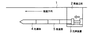
(1)単純な圧入方式
図1に示すように、先導体4、及びこれに追従する推進管5を発進立坑2に設置されている元押装置3を用いて、地盤1内に一度に圧入して推進を行う単純な圧入方式であり、静的圧入推進工法である。
【0004】
(2)複推進による圧入方式
図2(a) に示すように、先端部に先端ヘッド6を搭載した先導体4を有し、総推進力を先導体4の先端へッド6にかかる前面抵抗力と追従する推進管5と地盤1の摩擦による摩擦抵抗力とに分散して推進可能にする複推進機構を持つ複推進による圧入方式であり、静的圧入推進工法である。推進時には、図2(b) に示すように、先導体4に内蔵された複推進ジャッキ7により先導体4に搭載した先端ヘッド6を先行させて推進させ、その後に図2(c) に示すように、先導体4と推進管5とを発進立坑2に設置されている元押装置3によって推進させる、複推進による圧入方式である。
【0005】
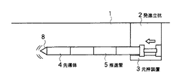
(3)先端ヘッドの偏心回転による圧入方式
図3に示すように、先端ヘッド8に効率的に土を排除するための動的な作動機構を装備した先導体4を有し、先端へッド8を図4(a) 〜(c) に示すように先導体4に対して偏心回転させ、この状態で発進立坑2に設置されている元押装置3を用いて先導体4と推進管5とを地盤1に圧入する回転式の圧入方式であり、動的な圧入方式である。
【0006】
(4)回転振動による圧入方式
図5に示すように、先端ヘッド8に効率的に土を排除するための動的な作動機構を装備した先導体4を有し、図6(a) に示すように先端へッド8の内部に重錘9と偏心回転する機構(図示せず)を装備し、図6(a) 〜(c) に示すように、先端へッド8の内部で重錘9を回転させて先導体の中心から外周方向に振動を発生させ、この状態で発進立坑2に設置されている元押装置3を用いて先導体4と推進管5とを地盤1に圧入する回転振動式の圧入方式であり、動的な圧入方式である。
【0007】
(5)衝撃式による圧入方式
図7に示すように、先端部が鋭利に形成された先導体4、及びこれに追従する推進管5を備えるが、先導体4の内部に図示しない重錘があり、この重錘に地盤1の上に設置したコンプレッサー10からエアホース11により圧搾空気を導き、重錘を前後動させて先導体4の先端部に衝撃力を発生させ、この状態で自走させて先導体4と推進管5とを地盤1に圧入する回転振動式の圧入方式であり、動的な圧入方式である。
【0008】
このように、いずれの圧入方式も、掘削排土方式による推進工法と比較して、カッタヘッドによる掘削機構および掘削された土砂を排出するための排士機構を装備しないために掘進速度が速いこと、システムの構成がシンプルになるためシステムの価格が安価であることから、工事期間を短縮できるとともに工事費を低減できる特徴を有している。また、無排土のため自然環境保護に貢献できるという特徴を有している。
【0009】
【発明が解決しようとする課題】
しかしながら、粘性士等軟らかい均質な地盤においては、単純な圧入方式あるいは複推進による方式による施工は問題ないが、地盤が砂質土と粘性土との互層地盤や、砂質土やレキ混じり土等の硬い地盤においては(1)の単純な圧入方式では発進立坑に設置される元押装置の総推力が弱いという問題点があった。
【0010】
また、(2)の複推進による圧入方式では、総推力を先端へッドの前面抵抗力と先導体に追従する推進管の管周面の摩擦抵抗力とに分散しているものの、先端へッドを圧入するための前面抵抗力が高くなり、土質についてはN値15程度までに適用が限定されるという問題点を有していた。
【0011】
一方、土質の適用拡大するために動的圧入推進工法である(3)の先端へッドの偏心回転による圧入方式では、砂質土やレキ混じり土等の硬い地盤において、先端へッドの偏心回転に必要なトルクが装備上、制限されるため、前面抵抗力の十分な削減効果が期待できないという問題を有している。
【0012】
また、(4)の回転振動による圧入推進工法では、先端のみに振動を発生できず先導体全体を振動させてしまうことから、地下水位の高い地盤では水締め効果により先導体が地盤から締め付けられ、先導体を推進することが不可能になるという問題を有しており、土質の適用の拡大はもとより実用化まで至っていない状態である。
【0013】
更に、(5)の衝撃式の圧入推進工法では、硬い地盤において推進が可能なものの、圧搾空気を用いるため推進距離が限定されることと、衝撃力発生のための振動や騒音が激しいため、施工現場の環境条件からその適用が制限されるといった問題を有していた。
【0014】
そこで、本発明は前記従来の圧入方式の有する問題点を解消し、硬い地盤においても無排土圧入による推進工法で管路を埋設でき、これまで掘削排土方式の推進工法で行っていた地盤においても無排土で圧入推進が可能となる動的圧入推進工法及びこの工法に用いられる推進装置を提供することを目的としている。
【0015】
また、振動を最小限に抑制可能で、騒音問題も発生せずに施工可能であり、更には、排土を発生させずに自然環境の保護にも貢献できる動的圧入推進工法及びこの工法に用いられる推進装置を提供することを目的としている。
【0016】
【課題を解決するための手段】
前記目的を達成する本発明の動的圧入推進工法は、発進立坑に設置された元押装置を用いて地盤内に先端部に先端ヘッドを備えた先導体を圧入して推進させ、これに推進管を追従させる無排土圧入による動的圧入推進工法であって、先端ヘッドを先導体の内部、あるいは元押装置に搭載した振動発生装置により振動可能に構成し、先端ヘッドを推進方向に平行な前後方向に振動させて地盤に所定の振動加速度を与え、この振動加速度により地盤の剪断強度を低下させて地盤の先端ヘッドの近傍の土粒子を流動化させ、先端ヘッドの前面における抵抗力果を最大限に低減させた状態で掘進を行い、N値30程度まで無排土で圧入を可能としたことを特徴としている。
【0017】
この場合、所定の振動加速度を、地盤の固有振動周波数前後の周波数による振動加速度とし、地盤を共振状態にするようにすることができる。
【0018】
また、前記目的を達成する本発明の動的圧入推進工法に使用する推進装置は、発進立坑に設置された元押装置と、この元押装置によって推進され、その後に推進管を追従させる、先端部に先端ヘッドを備えた先導体と、先導体の内部、あるいは元押装置に搭載され、先端ヘッドを振動させる振動発生装置と、先端ヘッドを、その推進方向に平行な前後方向に所定の振動加速度で振動させるように、振動発生装置を制御する制御装置とを備えることを特徴としている。
【0019】
この場合、先導体の内部にセンサを搭載し、これらのセンサの検出値を制御装置に設けた演算装置に取り込み、先端ヘッドの前面抵抗を最小とする振動数、振幅、振動力を演算し、地盤の状況に応じた最適な振動数、振幅、振動力を先端ヘッドに発生させるように構成することができる。
【0020】
本発明の動的圧入推進工法及びこの工法に用いられる推進装置によれば、粘性土から砂質土、砂レキ士といった地盤まで、無排土圧入による推進工法で管路を埋設でき、これまで掘削排土方式の推進工法で行っていた地盤においても無排土で圧入推進が可能である。このため、推進方向と平行な方向に先端ヘッドを振動させる無排土圧入による本発明の推進工法においては、掘削機構および排土機構を搭載しないことから、高速で掘進できることから工事期間が短縮できること、システムがシンプルなため装置の価格が安価なこと、排土といった産業廃棄物を発生しないことから、工事費が大幅に削減可能である。
【0021】
また、振動を最小限に抑制可能なことから、騒音といった問題も発生せずに施工可能であり、更には、排土といった産業廃棄物を発生しないことから、自然環境の保護にも貢献できる。
【0022】
【発明の実施の形態】
以下添付図面を用いて本発明の実施の形態を具体的な実施例に基づいて詳細に説明する。なお、本発明の実施例の構成において、図1から図7で説明した従来装置の構成部材と同じ構成部材には同じ符号を付して説明する。
【0023】
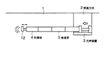
図8は本発明の動的圧入推進工法に用いられる推進装置の一実施例の構成を示すものである。この実施例の推進装置も、発進立坑2に設置されている元押装置3を用いて地盤1内に先端部に先端ヘッド12を備えた先導体4を圧入して推進させ、これに推進管5を追従させる動的圧入推進工法を行うものである。先端ヘッド12は図示しない駆動機構により推進方向に平行な方向に振動させることができる。先端ヘッド12の駆動機構は、先導体4の内部、或いは発進立坑2に設置した元押装置3に搭載する振動発生機構とすることができる。この実施例では推進ヘッド12の形状はフラットであるが、コーン型でもよい。
【0024】
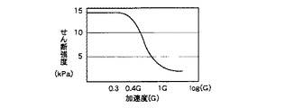
ところで、地盤に振動加速度0.3〜0.4G以上を付与すると、図9に示す振動加速度の付与により土の剪断強度の低下特性図から分かるように、その地盤の剪断強度が低下し、土粒子の流動化現象が生じることが一般的に知られている。このような振動加速度の付与による地盤の剪断強度低下の効果を最大限に引き出すためには、地盤を共振状態にすることが必要である。
【0025】
地盤を強制減衰振動体として考えると、図10に示すような強制減衰振動モデルが出来上がる。図11はこの強制減衰振動モデルの一般解を、振動数と加速度、或いは振幅を軸に示したグラフである。このグラフから、共振状態(グラフのピーク部分)となる固有振動周波数(図には固有振動数と記載)前後で振動加速度を地盤に付与すれば、地盤の剪断強度を最も効率的に低下できる。また、振動力を増加させると共振状態を発生可能な加速度あるいは振幅が増加するので、更に地盤の剪断強度の低下効果が期待できる。
【0026】
このことから、地盤の固有振動数前後の振動加速度を、図8に示した先導体4の先端へッド12を振動させることによって付与することにより、先導体4の前面の土の剪断抵抗を低下させることができると共に、一時的にかつ局所的に土粒子を流動化することができ、効率的な土粒子の再配列が可能になり、先導体4の圧入による前面抵抗力を大幅に低減できることになる。
【0027】
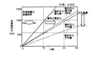
図12はN値20程度の砂質地盤において、本発明の動的圧入推進工法を用いた場合の、先導体4の先端ヘッド12に加わる前面抵抗力の低減効果を、振動数をパラメータとして示すものである。また、図13は静的な単純圧入方式と本発明の動的圧入推進工法における先導体4の先端へッド12に加わる前面抵抗力の低減効果を、N値をパラメータとして示したものである。
【0028】
本発明では、砂質土からレキ混じり土等の硬い地盤においても、先端へッド12のみを推進方向に平行に振動させるという動的方式を用いることから、先導体4の前面にのみ上述の振動加速度の効果が得られることが特徴である。図12は目標とする硬土質地盤(N値20程度)において、本発明の動的圧入推進工法による前面抵抗低減の効果を示したグラフであり、10〜20Hz程度の振動数を地盤に与えることにより、先導体4の先端へッド12に加わる前面抵抗力を30%以上低減可能である。
【0029】
また、図13に示すように、先導体4の装備能力を1000kNと考えると、従来の静的圧入推進工法ではN値15程度までが限界であったのに対して、本発明の動的圧入推進工法では、同じ装備能力において土質のN値が30程度の硬い地盤まで、上述の振動加速度効果により掘進可能となる。
【0030】
更に、本発明による動的圧入推進工法では、図14に示すように先導体4の中に、先端ヘッド12の変位計13、荷重変換器13、及び加速度計15等のセンサを内蔵しており、これらのセンサからの検出データは演算器16を通じて運転操作盤17に入力され、測定結果がモニタ18に表示される。また、先端ヘッド12への制御信号もこの運転操作盤17から演算器16を介して先導体4に伝えられる。
【0031】
先導体4内に搭載したセンサからの情報により、本発明の推進装置の操作者は、先端へッド12の前面抵抗力、振動力、振動数、加速度、振幅等をリアルタイムでモニタ18によって監視することができ、地盤の状況に応じて先導体の前面抵抗力を最小にする最適振動制御を行うことが可能である。具体的には、操作者は地盤に応じた固有振動数による振動加速度を地盤に付与し、振動力を増加させて振幅を最大にする振動制御を行うことができる。即ち、本発明の制御方法によれば、図11に示した共振状態を常時発生させると共に、振動加速度による効果を振動力を増加させることで増大させることができるので、一層効率的に前面抵抗低減効果が得られる。
【0032】
以上のことから、本発明の推進装置を用いた動的圧入推進工法では、粘性土から砂質土、レキ混じり土といった、これまで掘削排土方式で行ってきた比較的硬い地盤においても、無排土圧入による高速で掘進が可能となる。このため、本発明の動的圧入推進工法では、比較的硬い地盤における掘削工期を短縮できると共に、産業廃棄物を発生しないことから工事費を大幅に削減可能となる。また、振動を最小限に抑制できるため、周辺への振動騒音といった問題も解決である。更には、無排土で圧入可能な土質及び口径の適用範囲が広がるため、産業廃棄物の発生をいっそう抑制できるため、自然環境の保護におおいに貢献できる。
【0033】
【発明の効果】
以上説明したように、本発明の先端ヘッドによる推進方向と平行な振動による動的な圧入推進工法によれば、粘性土から砂質土、砂レキ土といった地盤まで、無排土圧入による推進工法で管路を埋設できる。また、これまで掘削排土方式の推進工法で行っていた地盤においても無排土で圧入推進が可能である。このため、推進方向と平行な方向に先端ヘッドを振動させる無排土圧入による本発明の推進工法においては、掘削機構および排土機構を搭載しないことから、高速で掘進できることから工事期間が短縮できること、システムがシンプルなため装置の価格が安価なこと、排土といった産業廃棄物を発生しないことから、工事費が大幅に削減可能であるという効果がある。
【0034】
また、振動を最小限に抑制可能なことから、騒音といった問題も発生せずに施工可能であり、更には、排土といった産業廃棄物を発生しないことから、自然環境の保護にも貢献できるという効果がある。
【図面の簡単な説明】
【図1】従来の単純な圧入方式を行う推進装置の構成を示す図である。
【図2】 従来の複推進による圧入方式の推進装置を示すものであり、(a) は先端ヘッドの推進前の状態、(b) は先端ヘッドを複推進ジャッキで推進させた状態、(c) は推進させた先端ヘッドに先導体と推進管を追従させた状態をそれぞれ示す図である。
【図3】従来の先端へッドが偏心回転する圧入方式の推進装置を示す図である。
【図4】 (a) から(c) は図3に示す推進装置の先端へッドの偏心回転を説明する図である。
【図5】従来の先端ヘッドが回転振動する圧入方式の推進装置を示す図である。
【図6】 (a) から(c) は図5に示す推進装置の先端へッドの回転振動を説明する図である。
【図7】従来の先端ヘッドが衝撃振動する圧入方式の推進装置を示す図である。
【図8】本発明の一実施例の動的圧入方式の推進装置を示す図である。
【図9】振動加速度の付与による土の剪断強度の低下状態を示すグラフである。
【図10】地盤を強制減衰振動体として考えた時の強制減衰振動モデルを示す図である。
【図11】図10の強制減衰振動モデルの振動数と加速度或いは振幅の関係を示すグラフである。
【図12】本発明の動的圧入方式の推進装置を用いた振動工法の砂地盤における振動数と先導体の先端の前面抵抗力低減効果を示す図である。
【図13】本発明の動的圧入方式の推進装置を用いた振動工法の砂地盤におけるN値と先導体の先端の前面抵抗力低減効果を示すグラフである。
【図14】図8の動的圧入方式の推進装置の最適振動制御を行うための制御方法を示すシステム図である。
【符号の説明】
1 地盤
2 発進立坑
3 元押装置
4 先導体
5 推進管
6 先端ヘッド
7 複推進ジャッキ
8 先端ヘッド
9 重錘
12 先端ヘッド
13 変位計
14 荷重変換器
15 加速度計
17 運転操作盤
18 モニタ[0001]
BACKGROUND OF THE INVENTION
TECHNICAL FIELD The present invention relates to a dynamic press-fitting propulsion method and a propulsion device used in this method, and in particular, embedment of underground lines such as telecommunications pipes, sewer pipes, gas pipes, etc. in the ground dynamically. The present invention relates to a dynamic press-fitting propulsion method and a propulsion device used in this method.
[0002]
[Prior art]
Conventionally, in the case of embedding telecommunications pipes, sewer pipes, gas pipes and the like in the ground, the non-cutting propulsion method is generally employed. When laying pipes in the ground by this non-open-cut propulsion method, the propulsion method by non-draining press-in is performed on relatively soft ground such as cohesive soil. In this propulsion method by non-extruded soil injection, a starting shaft is first formed on the ground, a main pushing device is installed on the starting vertical shaft, and the leading conductor is pushed from the main pushing device to the ground in the direction of laying the pipeline, Following this tip conductor, the propulsion pipe is laid continuously following the tip conductor. The following types of propulsion methods using undischarged soil injection are known.
[0003]
(1) Simple press-fitting method As shown in FIG. 1, the
[0004]
(2) Press-fitting method by double propulsion As shown in FIG. 2 (a), the
[0005]
(3) Press-in method by eccentric rotation of the tip head As shown in FIG. 3, the
[0006]
(4) Press-fitting method by rotational vibration As shown in FIG. 5, the
[0007]
(5) Impact-type press-fitting method As shown in FIG. 7, a
[0008]
Thus, compared with the propulsion method using the excavation and excavation method, any press-fitting method has a faster excavation speed because it does not include a excavation mechanism using a cutter head and an exhaust mechanism for discharging excavated earth and sand. Since the system configuration is simple and the system price is low, the construction period can be shortened and the construction cost can be reduced. In addition, it has the feature that it contributes to the protection of the natural environment because it is free of soil.
[0009]
[Problems to be solved by the invention]
However, in soft and homogeneous ground such as a viscometer, there is no problem with construction by a simple press-fitting method or double propulsion method, but the ground is a double-layered ground of sandy soil and viscous soil, sandy soil or soil mixed with reki, etc. In the hard ground, the simple press-fitting method (1) has a problem that the total thrust of the main pushing device installed in the start shaft is weak.
[0010]
In addition, in the press-fitting method with double propulsion (2), the total thrust is distributed to the front resistance of the tip head and the friction resistance of the pipe peripheral surface of the propulsion pipe following the leading conductor, but to the tip. The front resistance for press-fitting the lid is increased, and the soil quality has a problem that the application is limited to an N value of about 15.
[0011]
On the other hand, in the press-fitting method by eccentric rotation of the tip head (3), which is a dynamic press-fitting propulsion method, in order to expand the application of soil properties, the tip of the tip head is not suitable for hard ground such as sandy soil or mixed soil. Since the torque required for the eccentric rotation is limited in terms of equipment , there is a problem that a sufficient reduction effect of the front resistance cannot be expected.
[0012]
In addition, in the press-fitting propulsion method using the rotational vibration of (4), the tip conductor cannot be vibrated only at the tip and the entire tip conductor is vibrated. Therefore, the tip conductor is tightened from the ground due to the water-tightening effect on the ground with a high groundwater level. However, there is a problem that it becomes impossible to promote the leading conductor, and the application of soil quality has not been extended to practical use.
[0013]
Furthermore, in the impact-type press-fitting propulsion method of (5), although propulsion is possible on hard ground, the propulsion distance is limited due to the use of compressed air, and the vibration and noise for generating impact force are severe, There was a problem that its application was restricted due to the environmental conditions of the construction site.
[0014]
Therefore, the present invention eliminates the problems of the conventional press-fitting method, and even in hard ground, the pipe line can be embedded by the propulsion method by non-draining press-fitting method, and the ground that has been carried out by the excavation and excavation method of propulsion method so far The purpose of the present invention is to provide a dynamic press-fit propulsion method capable of press-fitting propulsion without soil and a propulsion device used in this method.
[0015]
In addition, the dynamic press-fitting propulsion method that can suppress vibrations, can be constructed without causing noise problems, and contribute to the protection of the natural environment without generating soil, and this method. The object is to provide a propulsion device to be used.
[0016]
[Means for Solving the Problems]
The dynamic press-fitting propulsion method of the present invention that achieves the above object is to propel and push a tip conductor having a tip head at the tip into the ground using a main pushing device installed in a start shaft. This is a dynamic press-fitting propulsion method with non-draining press-fitting to follow the pipe, and the tip head is configured to be able to vibrate inside the tip conductor or by a vibration generator mounted on the main pusher, and the tip head is parallel to the propulsion direction. The soil is vibrated in the longitudinal direction to give a predetermined vibration acceleration to the ground, and this vibration acceleration reduces the shear strength of the ground to fluidize the soil particles in the vicinity of the tip head of the ground, resulting in a resistance force effect on the front surface of the tip head. It is characterized in that excavation is carried out in a state where the slag is reduced to the maximum, and press-fitting is possible without soiling up to an N value of about 30.
[0017]
In this case, the predetermined vibration acceleration can be a vibration acceleration with a frequency around the natural vibration frequency of the ground so that the ground is in a resonance state.
[0018]
Further, the propulsion device used in the dynamic press-fitting propulsion method of the present invention that achieves the above object is a main pushing device installed in the start shaft, and a propellant that is propelled by the main pushing device and then follows the propelling pipe. A tip conductor with a tip head in the part, a vibration generator mounted on the inside of the tip conductor or in the main pushing device and vibrating the tip head, and a predetermined vibration in the front-rear direction parallel to the propulsion direction of the tip head And a control device that controls the vibration generating device so as to vibrate with acceleration.
[0019]
In this case, sensors are mounted inside the leading conductors, and the detection values of these sensors are taken into a calculation device provided in the control device, and the frequency, amplitude, and vibration force that minimize the front resistance of the tip head are calculated. The tip head can be configured to generate the optimum frequency, amplitude, and vibration force according to the ground conditions.
[0020]
According to the dynamic press-fitting propulsion method of the present invention and the propulsion device used in this method, it is possible to embed a pipe line from a cohesive soil to a ground such as sandy soil or sand repellent by a propulsion method by non-exhaust soil press-fitting. It is possible to press-fit without soil removal even on the ground that has been excavated and expelled. For this reason, in the propulsion method of the present invention by non-extruding press-fitting that vibrates the tip head in a direction parallel to the propulsion direction, since the excavation mechanism and the excavation mechanism are not mounted, the construction period can be shortened because the excavation mechanism and the excavation mechanism can be carried out at high speed. Because the system is simple, the cost of the equipment is low, and industrial waste such as earth removal is not generated, so construction costs can be greatly reduced.
[0021]
In addition, since vibration can be suppressed to a minimum, construction can be performed without causing problems such as noise. Furthermore, since industrial waste such as soil discharge is not generated, it can contribute to the protection of the natural environment.
[0022]
DETAILED DESCRIPTION OF THE INVENTION
Embodiments of the present invention will be described in detail below based on specific examples with reference to the accompanying drawings. In addition, in the structure of the Example of this invention, the same code | symbol is attached | subjected and demonstrated to the same structural member as the structural member of the conventional apparatus demonstrated in FIGS.
[0023]
FIG. 8 shows the structure of an embodiment of a propulsion device used in the dynamic press-fitting propulsion method of the present invention. The propulsion device of this embodiment also uses the main pushing
[0024]
By the way, when the vibration acceleration of 0.3 to 0.4 G or more is applied to the ground, the shear strength of the ground decreases due to the application of the vibration acceleration shown in FIG. It is generally known that particle fluidization occurs. In order to maximize the effect of lowering the shear strength of the ground by applying such vibration acceleration, it is necessary to bring the ground into a resonance state.
[0025]
Considering the ground as a forced damped vibrator, a forced damped vibration model as shown in FIG. 10 is completed. FIG. 11 is a graph showing the general solution of this forcedly damped vibration model with the frequency and acceleration or amplitude as axes. From this graph, if the vibration acceleration is applied to the ground before and after the natural vibration frequency (denoted as the natural frequency in the figure) in a resonance state (peak portion of the graph), the shear strength of the ground can be reduced most efficiently. Further, when the vibration force is increased, the acceleration or amplitude capable of generating a resonance state is increased, so that an effect of lowering the shear strength of the ground can be expected.
[0026]
From this, the vibration acceleration around the natural frequency of the ground is applied by vibrating the
[0027]
FIG. 12 shows the effect of reducing the front resistance applied to the
[0028]
In the present invention, since the dynamic method of vibrating only the
[0029]
Further, as shown in FIG. 13, when the equipment capacity of the leading
[0030]
Furthermore, in the dynamic press-fitting propulsion method according to the present invention, as shown in FIG. 14, sensors such as a displacement meter 13 of the
[0031]
Based on information from the sensor mounted in the leading
[0032]
From the above, the dynamic press-fitting propulsion method using the propulsion device of the present invention has no effect even on relatively hard ground, which has been carried out by excavation and soiling methods, such as clay soil, sandy soil, and mixed soil. The excavation can be performed at high speed by press-fitting the earth. For this reason, in the dynamic press-fitting propulsion method of the present invention, the excavation work period in a relatively hard ground can be shortened, and since no industrial waste is generated, the construction cost can be greatly reduced. In addition, since vibration can be suppressed to a minimum, problems such as vibration noise to the surroundings can be solved. Furthermore, since the applicable range of soil quality and caliber that can be press-fitted without draining is expanded, the generation of industrial waste can be further suppressed, which can greatly contribute to the protection of the natural environment.
[0033]
【The invention's effect】
As explained above, according to the dynamic press-fitting propulsion method using vibration parallel to the propulsion direction by the tip head of the present invention, the propulsion method by non-draining press-fitting from clay soil to ground such as sandy soil and sand repellent soil. The pipe can be buried with. In addition, it is possible to carry out press-fitting propulsion without soil even on the ground that has been excavated and expelled. For this reason, in the propulsion method of the present invention by non-extruding press-fitting that vibrates the tip head in a direction parallel to the propulsion direction, since the excavation mechanism and the excavation mechanism are not mounted, the construction period can be shortened because the excavation mechanism and the excavation mechanism can be carried out at high speed. Since the system is simple, the price of the apparatus is low, and industrial waste such as earth removal is not generated, so that the construction cost can be greatly reduced.
[0034]
In addition, since vibration can be suppressed to a minimum, it can be constructed without causing problems such as noise. Furthermore, since industrial waste such as soil is not generated, it can contribute to the protection of the natural environment. effective.
[Brief description of the drawings]
FIG. 1 is a diagram showing a configuration of a conventional propulsion device that performs a simple press-fitting method.
FIG. 2 shows a conventional press-fitting type propulsion device using double propulsion , where (a) shows a state before propulsion of the tip head, (b) shows a state in which the tip head is propelled by a double propulsion jack, (c ) Is a diagram showing a state in which the leading conductor and the propelling pipe are made to follow the propelled tip head.
FIG. 3 is a view showing a press-fitting type propulsion apparatus in which a conventional tip head rotates eccentrically.
4 (a) to (c) are diagrams for explaining the eccentric rotation of the tip head of the propulsion device shown in FIG. 3. FIG.
FIG. 5 is a diagram showing a press-fitting type propulsion device in which a conventional tip head rotates and vibrates.
6 (a) to 6 (c) are diagrams for explaining rotational vibration of a tip head of the propulsion device shown in FIG.
FIG. 7 is a view showing a press-fitting type propulsion device in which a conventional tip head is subjected to shock vibration.
FIG. 8 is a diagram showing a dynamic press-fitting propulsion device according to an embodiment of the present invention.
FIG. 9 is a graph showing a state in which the shear strength of soil is lowered due to application of vibration acceleration.
FIG. 10 is a diagram showing a forced damped vibration model when the ground is considered as a forced damped vibrator.
11 is a graph showing the relationship between the frequency and acceleration or amplitude of the forcedly damped vibration model of FIG.
FIG. 12 is a diagram showing the frequency reduction effect on the sand ground of the vibration method using the dynamic press-fitting type propulsion device of the present invention and the effect of reducing the front resistance force at the tip of the leading conductor.
FIG. 13 is a graph showing the N value and the effect of reducing the front resistance force at the tip of the leading conductor in the sand ground of the vibration method using the dynamic press-fitting propulsion device of the present invention.
14 is a system diagram showing a control method for performing optimal vibration control of the dynamic press-fitting propulsion device of FIG. 8; FIG.
[Explanation of symbols]
DESCRIPTION OF
Claims (2)
前記先端ヘッド(12)を、前記先導体(4) の内部、あるいは前記元押装置(3) に搭載した振動発生装置により振動可能に構成し、
前記先端ヘッド(12)を、推進方向に平行な前後方向に振動させて前記地盤(1) に前記先導体(4)の内部に搭載されたセンサからの情報に基づく当該地盤(1) の固有振動周波数前後の周波数による振動加速度を与え、前記地盤(1) を共振状態とし、
この振動加速度により前記地盤(1) の剪断強度を低下させて前記地盤(1) の、前記先端ヘッド(12)の近傍の土粒子を流動化させ、
前記先端ヘッド(12)の前面における抵抗力を低減させた状態で掘進を行い、
N値30程度まで無排土で圧入を可能としたことを特徴とする動的圧入推進工法。The leading conductor (4) with the tip head (12) at the tip is pressed into the ground (1) using the main pushing device (3) installed in the start shaft (2) and propelled to this. A dynamic press-fitting propulsion method by non-draining press-fitting to follow the pipe (5),
The tip head (12) is configured to be vibrated by a vibration generator mounted in the leading conductor (4) or in the main pushing device (3),
The tip head (12) is vibrated in the front-rear direction parallel to the propulsion direction and is inherent to the ground (1) based on information from a sensor mounted on the ground (1) inside the leading conductor (4). Giving vibration acceleration at frequencies around the vibration frequency, and making the ground (1) in a resonance state,
Due to this vibration acceleration, the soil (1) is reduced in shear strength to fluidize soil particles in the vicinity of the tip head (12) of the ground (1),
Performing excavation in a state where the resistance force on the front surface of the tip head (12) is reduced,
Dynamic press-fit propulsion method characterized by enabling press-fitting without soiling up to an N value of about 30.
発進立坑(2) に設置された元押装置(3) と、
後に追従させる推進管(5)を介して前記元押装置(3)によって推進され、先端部に先端ヘッド(12)を、内部にセンサを有する先導体(4) と、
前記先導体(4) の内部、あるいは前記元押装置(3) に搭載され、前記先端ヘッド(12)を振動させる振動発生装置と、
前記先端ヘッド(12)を、その推進方向に平行な前後方向に所定の振動加速度で振動させるように、前記振動発生装置を制御する制御装置と、
前記センサの検出値を取り込み、前記先端ヘッド(12)の前面抵抗を最小とする振動数、振幅、振動力を演算する演算装置と、
を備え、
前記演算装置により演算した振動数、振幅、振動力を前記先端ヘッド(12)に発生させることを特徴とする動的圧入推進工法に用いられる推進装置。A propulsion device used in the dynamic press-fitting propulsion method according to claim 1 ,
A main pushing device (3) installed in the start shaft (2),
Driven by the main pushing device (3) through a propelling pipe (5) to be followed later, a tip head (12) at the tip, and a leading conductor (4) having a sensor inside,
A vibration generator mounted on the inside of the leading conductor (4) or on the main pushing device (3) and vibrating the tip head (12);
A control device for controlling the vibration generating device so as to vibrate the tip head (12) at a predetermined vibration acceleration in the front-rear direction parallel to the propulsion direction;
An arithmetic unit that takes in the detection value of the sensor and calculates the vibration frequency, amplitude, and vibration force that minimize the front resistance of the tip head (12);
With
A propulsion device used in the dynamic press-fitting propulsion method, wherein the tip head (12) generates the vibration frequency, amplitude, and vibration force calculated by the arithmetic device.
Priority Applications (1)
| Application Number | Priority Date | Filing Date | Title |
|---|---|---|---|
| JP2001133533A JP3683509B2 (en) | 2001-04-27 | 2001-04-27 | Dynamic press-fitting propulsion method and propulsion device used in this method |
Applications Claiming Priority (1)
| Application Number | Priority Date | Filing Date | Title |
|---|---|---|---|
| JP2001133533A JP3683509B2 (en) | 2001-04-27 | 2001-04-27 | Dynamic press-fitting propulsion method and propulsion device used in this method |
Publications (2)
| Publication Number | Publication Date |
|---|---|
| JP2002327596A JP2002327596A (en) | 2002-11-15 |
| JP3683509B2 true JP3683509B2 (en) | 2005-08-17 |
Family
ID=18981376
Family Applications (1)
| Application Number | Title | Priority Date | Filing Date |
|---|---|---|---|
| JP2001133533A Expired - Lifetime JP3683509B2 (en) | 2001-04-27 | 2001-04-27 | Dynamic press-fitting propulsion method and propulsion device used in this method |
Country Status (1)
| Country | Link |
|---|---|
| JP (1) | JP3683509B2 (en) |
Cited By (1)
| Publication number | Priority date | Publication date | Assignee | Title |
|---|---|---|---|---|
| CN110067561A (en) * | 2019-04-26 | 2019-07-30 | 中铁二十三局集团有限公司 | Under wear both wired Urban Underground mining sectbn construction methods |
Families Citing this family (1)
| Publication number | Priority date | Publication date | Assignee | Title |
|---|---|---|---|---|
| CN105782564B (en) * | 2016-05-05 | 2018-06-05 | 江西建工第三建筑有限责任公司 | Push pipe mud physics touch-control drag reduction method |
-
2001
- 2001-04-27 JP JP2001133533A patent/JP3683509B2/en not_active Expired - Lifetime
Cited By (1)
| Publication number | Priority date | Publication date | Assignee | Title |
|---|---|---|---|---|
| CN110067561A (en) * | 2019-04-26 | 2019-07-30 | 中铁二十三局集团有限公司 | Under wear both wired Urban Underground mining sectbn construction methods |
Also Published As
| Publication number | Publication date |
|---|---|
| JP2002327596A (en) | 2002-11-15 |
Similar Documents
| Publication | Publication Date | Title |
|---|---|---|
| JPS61294085A (en) | Method and device for moving and forming underground path insoil | |
| US3283833A (en) | Sonic conduit driving system | |
| JP3683509B2 (en) | Dynamic press-fitting propulsion method and propulsion device used in this method | |
| JP2006169942A (en) | Vibrating-rotating pile driver and vibrating-rotating pile driving method | |
| JP5016947B2 (en) | Solidification material vibration injection method and apparatus | |
| JP3872376B2 (en) | Diameter expansion propulsion device | |
| JPH0721280B2 (en) | Non-removal soil promotion method for buried pipes | |
| JPH1176940A (en) | Vibration inducting device | |
| JP2003105794A (en) | Vibration control mechanism of operating arm | |
| JPH11243705A (en) | Levee building machine | |
| JPS63118494A (en) | Method of existing pipe exchange construction by high-frequency excitation | |
| JP2976330B2 (en) | Excavator-mounted handy vibro hammer | |
| JP3523586B2 (en) | Vibration control device for vibration generator | |
| JPS6354117B2 (en) | ||
| JPS6156757B2 (en) | ||
| JPH0230893A (en) | Tunnel excavator | |
| JP2001073682A (en) | Buried tube renewing method and device therefor | |
| JP2879135B2 (en) | Drilling method and equipment for foundation ground | |
| JPH0224473A (en) | Consolidation type slit cutter | |
| JPH11140871A (en) | Screwed-in type steel pipe pile with wing | |
| AU2020201411A1 (en) | Unclogging of a discharge opening of a tunnel boring machine by ultrasonic waves | |
| JPS59199997A (en) | Vibration type control embedding apparatus | |
| JP2794324B2 (en) | Underground pile driving method | |
| JPH11117280A (en) | Compacting device and compacting construction method using this device | |
| JP2004162461A (en) | Ultrasonic vibration type underground boring method and device thereof |
Legal Events
| Date | Code | Title | Description |
|---|---|---|---|
| A977 | Report on retrieval |
Free format text: JAPANESE INTERMEDIATE CODE: A971007 Effective date: 20041026 |
|
| A131 | Notification of reasons for refusal |
Free format text: JAPANESE INTERMEDIATE CODE: A131 Effective date: 20041102 |
|
| A521 | Written amendment |
Free format text: JAPANESE INTERMEDIATE CODE: A523 Effective date: 20041216 |
|
| A131 | Notification of reasons for refusal |
Free format text: JAPANESE INTERMEDIATE CODE: A131 Effective date: 20050201 |
|
| A521 | Written amendment |
Free format text: JAPANESE INTERMEDIATE CODE: A523 Effective date: 20050331 |
|
| TRDD | Decision of grant or rejection written | ||
| A01 | Written decision to grant a patent or to grant a registration (utility model) |
Free format text: JAPANESE INTERMEDIATE CODE: A01 Effective date: 20050510 |
|
| A61 | First payment of annual fees (during grant procedure) |
Free format text: JAPANESE INTERMEDIATE CODE: A61 Effective date: 20050525 |
|
| R150 | Certificate of patent or registration of utility model |
Ref document number: 3683509 Country of ref document: JP Free format text: JAPANESE INTERMEDIATE CODE: R150 Free format text: JAPANESE INTERMEDIATE CODE: R150 |
|
| FPAY | Renewal fee payment (event date is renewal date of database) |
Free format text: PAYMENT UNTIL: 20090603 Year of fee payment: 4 |
|
| FPAY | Renewal fee payment (event date is renewal date of database) |
Free format text: PAYMENT UNTIL: 20090603 Year of fee payment: 4 |
|
| FPAY | Renewal fee payment (event date is renewal date of database) |
Free format text: PAYMENT UNTIL: 20100603 Year of fee payment: 5 |
|
| FPAY | Renewal fee payment (event date is renewal date of database) |
Free format text: PAYMENT UNTIL: 20100603 Year of fee payment: 5 |
|
| FPAY | Renewal fee payment (event date is renewal date of database) |
Free format text: PAYMENT UNTIL: 20110603 Year of fee payment: 6 |
|
| FPAY | Renewal fee payment (event date is renewal date of database) |
Free format text: PAYMENT UNTIL: 20120603 Year of fee payment: 7 |
|
| FPAY | Renewal fee payment (event date is renewal date of database) |
Free format text: PAYMENT UNTIL: 20130603 Year of fee payment: 8 |
|
| FPAY | Renewal fee payment (event date is renewal date of database) |
Free format text: PAYMENT UNTIL: 20140603 Year of fee payment: 9 |
|
| S531 | Written request for registration of change of domicile |
Free format text: JAPANESE INTERMEDIATE CODE: R313531 |
|
| R350 | Written notification of registration of transfer |
Free format text: JAPANESE INTERMEDIATE CODE: R350 |
|
| EXPY | Cancellation because of completion of term |