JP3683239B2 - Library device - Google Patents
Library device Download PDFInfo
- Publication number
- JP3683239B2 JP3683239B2 JP2002218474A JP2002218474A JP3683239B2 JP 3683239 B2 JP3683239 B2 JP 3683239B2 JP 2002218474 A JP2002218474 A JP 2002218474A JP 2002218474 A JP2002218474 A JP 2002218474A JP 3683239 B2 JP3683239 B2 JP 3683239B2
- Authority
- JP
- Japan
- Prior art keywords
- magazine
- shutter
- cartridge
- gear
- lever
- Prior art date
- Legal status (The legal status is an assumption and is not a legal conclusion. Google has not performed a legal analysis and makes no representation as to the accuracy of the status listed.)
- Expired - Fee Related
Links
Images


Classifications
-
- G—PHYSICS
- G11—INFORMATION STORAGE
- G11B—INFORMATION STORAGE BASED ON RELATIVE MOVEMENT BETWEEN RECORD CARRIER AND TRANSDUCER
- G11B15/00—Driving, starting or stopping record carriers of filamentary or web form; Driving both such record carriers and heads; Guiding such record carriers or containers therefor; Control thereof; Control of operating function
- G11B15/675—Guiding containers, e.g. loading, ejecting cassettes
- G11B15/68—Automatic cassette changing arrangements; automatic tape changing arrangements
- G11B15/682—Automatic cassette changing arrangements; automatic tape changing arrangements with fixed magazines having fixed cassette storage cells, e.g. in racks
- G11B15/6835—Automatic cassette changing arrangements; automatic tape changing arrangements with fixed magazines having fixed cassette storage cells, e.g. in racks the cassettes being transferred to a fixed recorder or player using a moving carriage
Description
【0001】
【発明の属する技術分野】
本発明は、ライブラリ装置に関し、特に、記録媒体が内蔵されたカートリッジを多数格納し、このカートリッジを移送機構によりドライブユニットへ移送して、内部の記憶媒体に対する読み書き処理を行なうライブラリ装置であって、複数のカートリッジ収納し得るマガジンをセット可能なライブラリ装置に関する。
【0002】
【従来の技術】
従来、コンピュータシステムにおける情報量の増大に伴い、大容量の情報を保管するための情報記憶装置として、磁気テープを内蔵するカートリッジ式記憶媒体(以後単にカートリッジと言う)を用いたライブラリ装置が知られている。このようなライブラリ装置は、カートリッジの投入および排出を行なうためのアクセスユニットと、カートリッジ内の記憶媒体に対してデータの記録/再生を行なうドライブユニットと、これらのアクセスユニットとドライブユニットとの間でカートリッジを移送するアクセッサロボット(以下、単にアクセッサという)とを含んで構成されている。
【0003】
従来の一般的なライブラリ装置の内部には、多数のカートリッジを収納するための複数の棚が備えられている。また、ライブラリ装置では、複数のカートリッジを外部から同時投入または外部に同時排出を行えるようになっている。このために、一般にライブラリ装置は、複数のカートリッジを収納したマガジンの投入/排出を行うアクセスユニット〔以下、CAS(Cartridge Access Station)と略記〕が備えられている。
【0004】
CASからライブラリ装置に複数のカートリッジを収納したマガジンを投入する際には、まず、オペレータがマガジンを装置の外部(オペレータが操作する側)からアクセスユニット内のマガジンドラム外周に装着し、次いで、このマガジンドラムを駆動モータにより回転駆動し、マガジンに収納された各カートリッジを装置内側(アクセッサが移動する空間側)へ向けるように配置している。逆に、複数のカートリッジを収納したマガジンをCASにより排出する際には、マガジンドラムを駆動モータにより回転駆動し、排出すべきマガジンを装置外側へ向けるように配置した後、そのマガジンをオペレータが取り出している。
【0005】
また別のタイプのライブラリ装置では、装置外側に回動可能なトレイを有しており、トレイが外部空間側へ傾いた状態でマガジンを搭載後、トレイを戻してマガジンに収納された各カートリッジが装置内側(アクセッサが移動する空間側)へ向けるように配置する。それから、装置内側に配置された、装置の内側と外側を遮断する回転扉を駆動モータにより回転駆動することにより開き、マガジンを装置内側に開放して複数のカートリッジの投入を行っている。逆に、CASよりマガジンを排出する際には、回転扉を駆動モータにより回転駆動し、マガジンを装置内側から遮断した後に、トレイを回動して外部空間側に傾け、マガジンを取り出すことによってカートリッジの排出を行っている。
【0006】
一方、このようなマガジンには、収納した複数のカートリッジが搬送時にマガジンから飛び出さないようにする飛び出し防止機構が設けられている。従来のマガジンにおけるカートリッジの飛び出し防止機構は、カートリッジの1つ1つに対して、カートリッジに設けられている切り欠き部(凹部)に飛び出しを防止するロックレバーを引っ掛けるものや、板ばね等で押し付けて固定させるものなどであった。
【0007】
【発明が解決しようとする課題】
しかしながら、前述のライブラリ装置におけるCASでは、それぞれの構造上以下のような課題があった。
【0008】
まず、マガジンドラムを有するCASでは、カートリッジの投入/排出時に、マガジンをドラムに装着してこのドラムと共に回転させなければならないため、マガジンが装着されたドラム全体を回転駆動するための駆動機構や、ドラムを回転可能に支持するための支持構造が必要であり、ライブラリ装置の複雑化や大型化を招くという課題があった。
【0009】
次に、装置外側に回動可能なトレイを有するCASでは、回転扉がマガジンを搭載した状態で回転するため、マガジン及びマガジンに搭載されたカートリッジに対して、回転扉が干渉しないためのスペースが必要であるという課題があった。また、これに加えて更に、トレイがマガジンを搭載した状態で回転するためのスペースも必要であり、更に、回転扉を回転駆動するための駆動機構が必要であり、ライブラリ装置の複雑化や大型化を招くという課題があった。
【0010】
そして、前述の2つの形式のCASは、両方共回転駆動にモータを使用しているので、駆動機構の小型化に限界があり、また駆動制御を行う必要がありライブラリ装置の大型化や複雑化を招くという課題があった。
【0011】
一方、従来のマガジンにおける、カートリッジに引っ掛けるロックレバーを用いたカートリッジの飛び出し防止機構は、その解除のために専用に設けたソレノイドやモータが必要であり、ロック解除用の機構の部品数が増え、コスト高、故障の要因になるなどの課題があった。また、カートリッジに押し付ける板ばねを用いたカートリッジの飛び出し防止機構は、板ばねによるカートリッジの固定力が弱いために、マガジンを振ったりなどした場合にはカートリッジがマガジンから飛び出してしまうという課題があった。
【0012】
本発明は、このような課題を解消するものであり、その第1の目的は、回転扉の駆動機構にモータを使用しない簡素かつコンパクトな構成により、マガジンの投入/排出機構の省スペース化を図ったライブラリ装置を提供することである。また、第2の目的は、マガジンからのカートリッジの飛び出しを防止する簡素な機構を備え、マガジンがライブラリ装置の中に入った際には、装置内のカートリッジの運搬機構のアクセスの妨げにならないようにしたライブラリ装置を提供することである。
【0013】
【課題を解決するための手段】
前記目的を達成する本発明のライブラリ装置は、以下に第1から第5の発明として示される。
【0014】
第1の発明は、記憶媒体を収容するカートリッジに対して処理を行うドライブユニットと、カートリッジを収納する複数の棚と、カートリッジを移送するアクセッサ、及びカートリッジを複数個収納可能なマガジンを投入/排出可能な機構とを備え、このマガジンにより装置内に対するカートリッジの投入/排出を行うライブラリ装置において、アクセッサが動作する内部空間とライブラリ装置の外部空間とを連通する連通空間に、マガジンの挿通空間を備えるフレームユニットを配置し、マガジンの挿通空間の、内部空間側を開閉するインナシャッタをフレームユニットに取り付けて前記マガジンの投入/排出機構を構成し、インナシャッタを、マガジンがセットされていない状態では、マガジンのセット後の領域を共有した状態で閉じているように構成すると共に、マガジンの一部に係合する第1の係合部を設けて構成し、マガジンには、第1の係合部に係合する第2の係合部を設け、挿通空間内にマガジンが挿入された時に、第1と第2の係合部が係合し、マガジンの挿入動作によってインナシャッタが開き、マガジンが挿通空間内のセット位置に達した時には、インナシャッタが開き切るように構成したことを特徴としている。
【0015】
第2の発明は、第1の発明において、インナシャッタを、フレームユニットに突設した回転軸に取り付けた回転扉として構成すると共に湾曲したシャッタ部を設け、第1の係合部を、インナシャッタの底板部の上に固定した略U字状のレバーとし、第2の係合部をマガジンの底部に突設した突起とし、マガジンが挿通空間内に挿入された時に、突起が進行するライン上に、レバーの開口部を位置させたことを特徴としている。
【0016】
第3の発明は、第1又は第2の発明において、マガジンの挿通空間の、外部空間側を開閉するアウタシャッタをフレームユニットに設け、アウタシャッタを、フレームユニットに突設した回転軸に対して、インナシャッタの外側に取り付けられた回転扉とすると共に、インナシャッタの湾曲したシャッタ部よりも半径の大きな湾曲したシャッタ部を設けたことを特徴としている。
【0017】
第4の発明は、第3の発明において、マガジンの上面に位置決め溝を設け、フレームユニットのアッパプレートには、マガジンがセット位置に達した時に、この位置決め溝に係合する保持レバーを設け、フレームユニットのアッパプレートに、回転軸に挿入すると共に、アウタシャッタの動きに連動する第1ギアと、この第1ギアに噛合する第2ギアを設け、マガジンがセット位置にセットされている時に、アウタシャッタを閉じることにより、第1ギアと第2ギアが連動し、第1ギアに突設されたアームと第2ギアに突設されたアームを用いて保持レバーを固定し、マガジンの位置を固定することを特徴としている。
【0018】
第5の発明は、第3の発明において、マガジンのカートリッジの出し入れ口側に、マガジン内に収納されたカートリッジの飛び出しを防止するカートリッジ脱落防止レバーを、出し入れ口と交差する方向に設け、このカートリッジ脱落防止レバーは、マガジンがセット位置にセットされた状態で、アウタシャッタを閉じる動作によって、出し入れ口の前から退避するようにしたことを特徴としている。
【0019】
第1の発明では、マガジンがセットされていない状態ではインナシャッタがマガジンのセット後の領域を共有した状態で閉じているので、装置内への異物の侵入を防止できると共に、ライブラリ装置の前後スペースを小さくすることができる。
【0020】
第2の発明では、インナシャッタが回転軸に取り付けられた回転扉であり、マガジンのライブラリ装置内への挿入により自動的に開く。
【0021】
第3の発明では、インナシャッタの外側に同軸上で回転する回転扉であるアウタシャッタが取り付けられているので、ライブラリ装置を小型化することができる。
【0022】
第4の発明では、マガジンがセット位置にセットされた状態でアウタシャッタを閉じることにより、マガジンの位置が固定される。
【0023】
第5の発明では、カートリッジ脱落防止レバーにより、マガジン内のカートリッジの飛び出しが確実に抑えられる。
【0024】
【発明の実施の形態】
以下添付図面を用いて本発明の実施形態を具体的な実施例に基づいて詳細に説明する。
【0025】
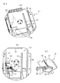
図1(a)は本発明が適用される磁気テープライブラリ装置100を正面側から見たものであり、(b)は背面側から見たものである。ライブラリ装置100の正面パネルには、磁気テープが内蔵されたカートリッジを複数個収納するマガジンを、このライブラリ装置100に出し入れするための媒体アクセスポート101がある。この実施例のライブラリ装置100には媒体アクセスポート101は2箇所あり、それぞれの媒体アクセスポート101からマガジンを出し入れすることができる。また、ライブラリ装置100の内部に収納されたカートリッジの交換や内部装置の点検は、扉102を開けることによっても行うことができる。そして、ライブラリ装置100の扉102にはオペレータパネル103が設けられており、装置に内蔵されたカートリッジの選択等の操作をこのオペレータパネル103を通じて行うことができる。
【0026】
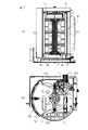
図2(a)は図1(a)に示すライブラリ装置100の内部構成を示すものである。また図1(b)は(a)のライブラリ装置100の内部構成を上から見たものである。ライブラリ装置100の内部には、カートリッジ15に対して記録再生を行うドライブユニット50と、カートリッジ15を複数個収納する収納棚60がある。この実施例では、ドライブユニット50は横方向に2列並べられ、縦方向に4個並べられており、合計8台装備されている。そして、このドライブユニット50と収納棚60の間でカートリッジ15を搬送するためのアクセッサロボット70が装置の中に設けられている。
【0027】
このようなライブラリ装置100は、コンピュータ、サーバ、パーソナルコンピュータにネットワークを介して接続され、各装置からのアクセスに応じて、カートリッジに情報を記録し、またカートリッジからの再生を行う。そのために、複数のカートリッジをライブラリ装置100内の収納棚60に収納している。更に、カートリッジの追加が必要になった場合には、マガジン40を利用して媒体アクセスポート101を介して、マガジン40に収納されたカートリッジをアクセッサロボット70により装置内の収納棚60に搬送することにより、カートリッジがライブラリ装置100内に投入される。また、ライブラリ装置100内のカートリッジを取り出す場合には、アクセッサロボット70によりライブラリ装置100の収納棚60からカートリッジを取り出し、これをマガジン40内に移動する。そして、このマガジン40を媒体アクセスポート101から取り出すことにより、カートリッジが取り出せる。
【0028】
このアクセッサロボット70は、ライブラリ装置100の中を3次元的に移動することができる。すなわち、アクセッサロボット70は図中矢印Aで示すように、ライブラリ装置100の高さ方向で上下に移動し、また、矢印Bで示すように、ライブラリ装置100の幅方向で往復運動する。更に、アクセッサロボット70のロボットハンド部分は、矢印Cで示す方向に回転する。これにより、アクセッサロボット70は、ライブラリ装置100内の収納棚60、ドライブユニット50の必要位置に移動することができ、移動した位置でカートリッジの抜き取り、装填を実行し、更に、保持したカートリッジを所定位置まで搬送することが可能となる。
【0029】
なお、このロボットハンドは、本出願人が既に出願した特願2002−207260号に記載されているように、カートリッジを把持するための爪部分の開閉動作、カートリッジに対して離接する方向の動作を1つの駆動源で行える構成となっている。
【0030】
図3はライブラリ装置100で使用されるカートリッジ15の1つの種類であるLTO媒体15Aを示すものであり、(a)はLTO媒体15Aを背面側から見たもの、(b)はLTO媒体15Aの正面図、(c)はLTO媒体15Aの平面図、(d)はLTO媒体15Aの背面図、(e)はLTO媒体15Aの側面図である。LTO媒体15Aの外寸は、図示のように、幅が105.4mm、奥行きが102mm、高さが21.5mmである。
【0031】
LTO媒体15Aには、その正面側に媒体識別用の凹部41Aがあり、背面側の両側面にはロボットハンドによって把持される凹部41が設けられている。また、背面にはこのカートリッジ15を識別するためのバーコードラベル44が貼付されている。LTO媒体15Aの正面側にある凹部41Aは、LTO媒体15Aの高さ方向全域に渡って設けられていない。
【0032】
図4はライブラリ装置100で使用されるカートリッジ15のもう1つの種類であるDLT媒体15Bを示すものであり、(a)はDLT媒体15Bを背面側から見たもの、(b)はDLT媒体15Bの正面図、(c)はDLT媒体15Bの平面図、(d)はDLT媒体15Bの背面図、(e)はDLT媒体15Bの側面図である。DLT媒体15Bの外寸は、図示のように、幅が105.4mm、奥行きが105.8mm、高さが25.4mmである。
【0033】
DLT媒体15Bにも、その正面側に媒体識別用の凹部41Bがあり、背面側の両側面にはロボットハンドによって把持される凹部41が設けられている。正面側には更に、蓋42、及び蓋42を開閉するためのヒンジ43が設けられている。また、背面にはこのカートリッジ15を識別するためのバーコードラベル44が貼付されている。DLT媒体15Bの正面側にある凹部41Bは、DLT媒体15Bの高さ方向のほぼ全域に渡って設けられている。
【0034】
磁気テープライブラリ装置では一般的に、LTO媒体15AやDLT媒体15Bの背面側にバーコードラベル44が貼付されている。このバーコードラベル44には、媒体に記録されているデータの情報が書かれており、ロボットハンドに内蔵されたCCDカメラユニットや、バーコードリーダユニット等によって、バーコードラベルに記載されたバーコードを読み取り、その情報を使ってバックアップ作業を行っている。
【0035】
ここで、図1(a)に示した本発明のライブラリ装置100の媒体アクセスポート101に設けられる、カートリッジ投入/排出機構(CAS)80の基本構成、及び複数のカートリッジ15を収納できるマガジン40の構成、及びこれらの動作について説明する。
【0036】
図5は、本発明の一実施例としてのライブラリ装置100におけるカートリッジ投入/排出機構(CAS)80の基本構成、及びマガジン40を示すものである。CAS80は、フレームユニット110、インナシャッタユニット120、アウタシャッタユニット130、及びシャッタロックユニット140の4つの部分から構成される。そして、フレームユニット110の上にマガジン40が挿入される。まず、このマガジン40の構成を、図6を用いて説明する。
【0037】
図6(a),(b)に示すように、マガジン40には、カートリッジ15を収納する収納棚(セル)19が複数段(図6に示す実施例では5段)設けられている。各セル19へのカートリッジ15の挿入や、各セル19からのカートリッジ15の取り出しは、マガジン40の正面側からのみ行えるようになっている。マガジン40の上面には、上部ハンドル51が取り付けられている。この上部ハンドル51は、マガジン40の持ち運び時にオペレータにより把持されるものである。マガジン40の背面には、把手であるセッティングハンドル52が取り付けられている。このセッティングハンドル52は、マガジン40をCAS80にセットする際や、CAS80から取り出す際にオペレータにより把持されるものである。
【0038】
また、マガジン40の上面には、マガジン40をCAS80にセットした際に、フレームユニット110側の後述するマガジン保持レバーと係合する位置決め溝45が形成されている。この位置決め溝45の前側には壁面48が形成されている。一方、マガジン40の底面には、マガジン40をフレームユニット110上に載置した際に、後述するフレーム下ベースのガイド溝と嵌合する脚部46,47と、マガジン40の挿入/排出動作時にフレーム下ベースのガイド溝を介してインナシャッタユニット120の底板上に配置されるシャッタ駆動用レバーと嵌合してインナシャッタユニット120を回転駆動させるシャッタ駆動用突起55が形成されている。
【0039】
なお、マガジン40には、カートリッジ15の誤挿入を防止するためのカートリッジ誤挿入防止レバー54や、マガジン40の運搬時に収納されたカートリッジ15が脱落するのを防止するためのカートリッジ脱落防止レバー53も備えられている。また、マガジン40の背面下部には、CAS80内でのマガジン40の位置決め、及び保持に使用されるブロック部56がある。
【0040】
図7(a)はCAS80のフレームユニット110の構成を分解して示すものであり、図7(b)は図7(a)に示したフレームユニット110を底面側から見たものである。フレームユニット110は、フレームベース111と、このフレームベース111の上の対向する位置に取り付けられるサイドフレーム112、113及びサイドフレーム112,113の上に掛け渡されるアッパプレート114とから構成される。
【0041】
フレームベース111の裏面側には、後述するインナシャッタユニットロック機構90と、インナとアウタのシャッタユニットが取り付けられるシャッタ軸72とがある。アッパプレート114には、第1のギア74、インナとアウタのシャッタユニットが取り付けられるシャッタ軸71、第2のギア75のギア軸73、及び2つのマガジン保持レバー77が設けられている。マガジン保持レバー77は、マガジン40が装置にセットされた時に、マガジン40の位置決め溝45に係合するものである。また、アッパプレート114の脇には、マガジンセンサ76が設けられている。そして、フレームベース111、サイドフレーム112、113、及びアッパプレート114によって囲まれた部分は、ライブラリ装置の内部におけるアクセッサの動作空間とライブラリ装置の外部空間とを直接的に連通接続する連通空間となっている。第1、第2のギア74、75、及びマガジン保持レバー77は、マガジン保持機構,マガジン誤挿入防止機構で使用するもので後に説明する。
【0042】
ここで、図8を用いて、フレームベース111の構成について詳細に説明する。図8(a)に示すフレームベース111の上面には、マガジン40をセットする際にマガジン40の脚部46,47と嵌合する第1、第2のガイド溝81,82Aと、シャッタ駆動用突起55と嵌合する第3のガイド溝83の3つの溝と、マガジン40の位置決め、保持、及び誤挿入防止機構で使用される2つの傾斜84がある。ガイド溝83は、途中からフレームベース111を貫通するスリットになっている。また、フレームベース111の後端部には、マガジン40の過挿入を防止するための壁面85が突設されている。
【0043】
図8(b)に透視して示すように、フレームべース111の裏面側には、マガジン40の挿入/排出動作に連動し、インナシャッタユニット120に対して機能するロック機構90が取付けられている。ロック機構90は、図8(c)に示すように、ベース部91,レバー92,ばね94により構成されている。レバー92はベース部91に突設された回転軸95に軸支されている。更に、このレバー92には、ベース部91に設けられた係止部98に一端が取り付けられている引張りばね94の他端が取り付けられていて、常時係止部98側に引っ張られている。一方、ベース部91にはこの引っ張りばね94によるレバー92の回転を止めるストッパ97が設けられている。そして、CAS80にマガジン40が投入されていない時には、レバー92はストッパ97に突き当たっている。また、レバー92の一方の自由端にはフック部96が形成されている。また、レバー92の他方の自由端にはローラ93が取り付けられている。このローラ93は、マガジン40が投入されていない時には、図8(b)に示すように、フレームベース111の第1のガイド溝81の中に突出するようになっている。
【0044】
図9(a)はインナシャッタユニット120の構成を示すものである。インナシャッタユニット120は、天井部120a、底板部120c、及び天井部120aと底板部120cの間に設けられた湾曲形状の壁を備えたシャッタ部120bとから構成される。シャッタ部120bは、CAS80にマガジン40が投入されていない時に、アクセッサの動作空間側から連通空間を遮断するためのものである。
【0045】
天井部120aの中央部に設けられた軸孔121には、フレームユニット110のアッパプレート114に設けられたシャッタ軸71が挿通される。また、底板部120cの中央部に設けられた軸孔122には、フレームユニット110のフレームベース111の底面に設けられたシャッタ軸72が挿通される。なお、軸孔121、122にはブッシュが取り付けられている。更に、アッパプレート120aのシャッタ部120bに近い部位には、遮蔽板としてのフラグ125が天井部120aを切り起こすことによって設けられている。
【0046】
底板部120cの上面には、マガジン40の挿入/排出動作時に、フレームベース111のガイド溝83を通るマガジン40のシャッタ駆動用突起55と嵌合するシャッタ駆動用レバー126が固着されている。このレバー126はU字状をしており、一方の内壁がオープン部126aとなっており、他方の内壁がクローズ部126bとなっている。即ち、マガジン40の投入時に、シャッタ駆動用突起55がレバー126内に進入し、オープン部126aを押せばシャッタ部120bが前述の連通空間を開く方向に回転し、マガジン40の排出時に、クローズ部126bを押せばシャッタ部120bが前述の連通空間を閉じる方向に回転する。このように、マガジン40の投入/排出動作が、このインナシャッタ駆動レバー126により、インナシャッタユニット120の回転動作に変換される。
【0047】
更に、底板部120cの上面にはインナシャッタロック軸123が突設されている。このロック軸123は、CAS80内にマガジン40が存在しない時、前述のロック機構90と共に、インナシャッタユニット120が閉じた状態を保持するために使用される、また、底板部120cにはばね107を引っ掛けるために底板部120cを切り起こした突起124が設けてあり、インナシャッタユニット120は、ばね107により前述の連通空間を常時閉じる方向に付勢されている。
【0048】
図9(b)はアウタシャッタユニット130の構成を示すものである。アウタシャッタユニット130も、天板部130a,底板部130c、及びアクセッサのCAS80へのアクセス時に、外部空間側から装置内への連通空間を遮断する湾曲壁を備えたシャッタ部130bから構成される。アウタシャッタユニット130は、インナシャッタユニット120を外側から覆うように取り付けられるものであり、シャッタ部130bの回転半径は、インナシャッタユニット120のシャッタ部120bの回転半径より大きくなっている。
【0049】
天井部130aの中央部に設けられた軸孔131には、フレームユニット110のアッパプレート114に設けられたシャッタ軸71が挿通される。また、底板部130cの中央部に設けられた軸孔132には、フレームユニット110のフレームベース111の底面に設けられたシャッタ軸72が挿通される。なお、軸孔131、132にはブッシュが取り付けられている。更に、天井部130aの縁部に近い部位には、連結軸133が突設されている。連結軸133は、インナシャッタユニット120の天井部120aの軸孔121の周囲の部分の半径よりも遠い位置にあり、フレームユニット110のアッパプレート114の上に、シャッタ軸71を介して配置されている第1のギア74の一方のアーム74Aの先端部に設けられた連結穴74aと嵌合する。この構成により、第1のギア74は、アウタシャッタユニット130と同期回転を行う。
【0050】
シャッタ部130bの端部には縦方向に把手137が設けてある。また、シャッタ部130bの中央部には縦方向に窓138が設けられている。把手137は、オペレータがアウタシャッタユニット130の開閉動作を行う際に使用するものである。また、フレームユニット110のアッパプレート114に設けられたギア軸73に取り付けられている第2のギア75は、第1のギア74と連結しており、アウタシャッタユニット130の開閉動作に連動して回転する。
【0051】
底板部130cの下面には、アウタシャッタロック軸134、シャッタセンサ141用の遮蔽板であるフラグ135、及び突起136が設けられている。アウタシャッタロック軸134は、アクセッサがCAS80にアクセスする時にアウタシャッタユニット130が開くことを禁じるように、アウタシャッタロック機構150のロックレバー147にロックされるものである。また、フラグ135は、アウタシャッタユニット130が閉じている時にシャッタセンサ141の位置に来て、アウタシャッタユニット130が閉じていることを検出するものである。更に、突起136はばね106を引っ掛けるためのものである。アウタシャッタユニット130は、アウタシャッタロック機構150により閉じた状態でロックされている時、このばね106により常時開く方向に付勢されており、ロック解放時に開く構造となっている。
【0052】
図10は、シャッタロックユニット140の構成を示すものである。シャッタロックユニット140は図10に示される通り、ベース部140aとアウタシャッタロック機構部150により構成されている。ベース部140aにはアウタシャッタロック機構部150のロックレバー147を取り付ける回転軸145、及びシャッタセンサ141が取り付けられている。またベース部140aには、取付け穴が設けられており、シャッタロックユニット140は、フレームユニット110にねじ止めされる。
【0053】
アウタシャッタロック機構150は、ソレノイド149,プランジャ148、ロックレバー147、及びばね146により構成されている。ソレノイド149はベース部140aにねじ止めされ、レバー147はベース部140aに突設された回転軸145に軸支されている。レバー147は取付軸144を介してソレノイド149のプランジャ148と連結されており、ソレノイド149の吸引動作によって、回転軸145を中心にして回転する。このレバー147の取付軸144と反対側の端部には平面部147aが形成されており、この平面部147aに隣接してロック部147bが設けられている。また、レバー147にはプランジャ148の復元用の引張りばね146が、ベース部140aに設けられた係止突起143との間に取り付けられている。この構成では、ソレノイド149が吸引動作を行わない通常状態では、レバー147は引っ張りばね146によってストッパ142の方向に付勢されており、ストッパ142に突き当たっている。
【0054】
図11(a),(b)、及び図12は、図10のシャッタロックユニット140が、アウタシャッタユニット130が閉じられた時にこれをロックする様子を示すものである。
【0055】
ソレノイド149が通電されていない状態で、アウタシャッタユニット130が閉じる方向に回転させてゆくと、図11(a)に示すように、アウタシャッタユニット130のアウタシャッタロック軸134がレバー147の先端部に形成された平面部147aに当接する。アウタシャッタユニット130が閉じる方向の回転を継続すると、アウタシャッタロック軸134によって平面部147aが押されるので、図11(b)に示すように、レバー147がばね146に抗して回転させられる。
【0056】
アウタシャッタユニット130が閉じる方向に更に回転すると、アウタシャッタロック軸134が平面部147aを乗り越える。すると、ばね146の復元力によりレバー147が戻り、図12に示すように、アウタシャッタロック軸134がロック部147bに係止される。この結果、アウタシャッタユニット130がシャッタロックユニット140によってロックされる。この状態では、アウタシャッタユニット130に設けられたフラグ135がシャッタロックユニット140のシャッタセンサ141を覆うので、アウタシャッタユニット130が完全に閉じてロックされた状態が検出される。
【0057】
本実施例のCAS80では、マガジン40を取り外した状態で、装置内部のアクセッサの動作空間が閉空間となるようにインナシャッタユニット120が設けられている。また、マガジン40がCAS80にセットされていない状態では、インナシャッタユニット120が外力等により開放できないようにするロック機構が設けられていて、装置内への誤挿入、異物の投入を禁止し、装置の安全性を確保している。これらインナシャッタユニット120の開閉,ロック機構のロック/解除は、オペレータがマガジン40を装置に投入、あるいは装置から排出する動作によってのみ行われ、他の駆動力を必要としない。
【0058】
以下に、マガジン40の投入/排出を行う際の、インナシャッタユニットロック機構90,及びインナシャッタユニット120の開閉機構の一連の動作について、図13から図16を参照しながら説明する。なお、図13と図14、及び図15(a)と図16(a)は、機能説明のためCAS80を底面側から見たものであり、マガジン40と各機構の位置関係がわかるように、複数部品を省略し、更に一部部品を透視図で示してある。また、図15(b)は図15(a)の状態を側面から見た状態を示し、図16(b)は図16(a)の状態を側面から見た状態を示している。
【0059】
マガジン40がCAS80に投入されていない時は、インナシャッタユニット120は閉じており、更に、インナシャッタユニットロック機構90によって回転をロックされている。マガジン40はオペレータにより背面の把手52を把持された状態でCAS80のマガジン投入口前まで運ばれ、フレームベース111のガイド溝81,82にマガジン40の脚部46,47の位置が合わされる。この状態から背面の把手52を把持した状態でマガジン40を装置内部方向に押すことにより、マガジン40は、その脚部46,47がガイド溝81,82の入り口部のテーパーによりガイドされながらガイド溝81,82に進入する。この状態が図13(a)に示される状態である。この状態では、ガイド溝81内に突出しているインナシャッタユニットロック機構90のレバー92の端部に設けられたローラ93が、マガジン40の脚部46の先端によって押される。
【0060】
マガジン40が装置内に更に挿入されると、ローラ93が押されてレバー92が回転し、インナシャッタユニット120のロック軸123がレバー92から開放される。更なるマガジン40の挿入により、図13(b)に示すように、ローラ93が脚部46の側面を走行するので、回転したレバー92の位置が保持される。また、マガジン40の進入により、マガジン40に設けられたシャッタ駆動用突起55がガイド溝83を貫通して、フレームベース111の裏面側に突出し、この突起55がフレームベース111の下方に位置するインナシャッタユニットの底板部120cにあるインナシャッダ駆動レバー126の中に入り、オープン部126aに当接する。
【0061】
マガジン40が更に挿入されると、シャッタ駆動用突起55がシャッタ駆動用レバー126のオープン部126aを押すことにより、図14に示すように、インナシャッタユニット120が回転して扉であるシャッタ部120bが開く。この実施例では、装置の内部スペースを小さくするために、インナシャッタユニット120が閉じている状態では、そのシャッタ部120bがマガジン40が装置にセットされた状態の領域に位置している。よって、マガジン40がシャッタ部120bと干渉する領域まで挿入される前に、シャッタ部120bを干渉領域から逃がす必要がある。この実施例では、マガジン40の挿入によってもシャッタ部120bがマガジン40に接触しない位置関係を保ちながら、シャッタ部120bが回転するように、マガジン40のシャッタ駆動用突起55とインナシャッタユニット120のインナシャッタ駆動レバー126が配置されている。
【0062】
マガジン40が更に装置内に挿入されると、図15(b)に示すように、マガジン40の背面下部に設けられたブロック部56が、フレームベース111の上平面に位置する傾斜部84と接触し、マガジン40が前方に傾斜する。この状態では、図15(a)に示すように、インナシャッタ駆動レバー126のオープン部126aとシャッタ駆動用突起55との係合が外れ、シャッタ部120bが開ききる。
【0063】
この後、更にマガジン40は、開いたシャッタ部120bが戻らないように、シャッタ駆動用突起55の側面でシャッタ駆動用レバー126のオープン部126aの先端と接触を続けながら挿入され、ブロック部56が傾斜部84を登り切ってこれを乗り越えることによって、図16(b)に示すセット位置に位置付けられる。
【0064】
このマガジン40のセット位置は、図16(a)に示すような位置になる。すなわち、マガジン40がセット位置に位置付けられた場合には、マガジン40の先端部分は、シャッタ部120bの閉鎖位置(図中破線で示す)と重なる位置に位置決めされる。これにより、マガジン40の位置は、アクセッサロボットのロボットハンド30の爪部6を挟持位置に移動するのみで、マガジン40に収納されているカートリッジ15の取り出しを行うことができる。これにより、ロボットハンド30自体を収納棚60、ドライブユニット50に接近する方向に移動させる必要がないため、ロボットハンド30としては、爪部6の移動、開閉を1つの駆動源で行うことができるものが利用できる。このため、ロボットハンド30の低価格化、小型化を実現でき、ライブラリ装置の小型化に寄与することが可能となる。
【0065】
以上のような動作で、セット位置に挿入されたマガジン40を引き出す時には、前述の動作と全く逆の動作を行えば良い。オペレータは、マガジン40の背面の把手52を把持した状態で、脚部46先端部を支点にしてマガジン40を上方に持ち上げて図15(b)の状態にする。そして、ブロック部56が傾斜部84に乗り上げた状態で、マガジン40を装置の外部方向に引くことによりマガジン40を排出することができる。
【0066】
ブロック部56が傾斜部84に乗り上げた状態でマガジン40を引くと、シャッタ駆動突起55が、図15(a)に示すように、インナシャッタユニット120のインナシャッタ駆動レバー126のクローズ部126bと係合する。更にマガジン40を引くと、シャッタ駆動用突起55がインナシャッタ駆動レバー126のクローズ部126bを押すことによりインナシャッタユニット120が回転し、図14、図13(b)の状態を経てシャッタ部120bが閉じる。
【0067】
マガジン40を更に引くと、シャッタ駆動用突起55がシャッタ駆動用レバー126のクローズ部126bから外れ、図13(a)に示すように、シャッタ部120bが閉じ切る。この状態では、マガジン40の脚部46の側面もレバー92の端部にあるローラ93から外れ、レバー92が開放され、ばね94による復元力よって戻り、インナシャッタユニット120のインナシャッタロック軸123と係合し、インナシャッタユニット120がロックされる。
【0068】
この実施例では、インナシャッタユニット120がばね107により常時閉じる方向に付勢されているので、インナシャッタ駆動レバー126のクローズ部126bが無くとも、インナシャッタユニット120はマガジン40を排出方向に引くことにより、挿入動作時の状態を逆から辿った動作を行い、自動的に閉じられてロックされる。
【0069】
次に、前述した挿入動作によりセット位置に位置付けられたマガジン40を保持する機構について説明する。装置内に挿入されたマガジン40は、図17(a)に示すように、左右方向がフレームユニット110のサイドフレーム112,113とフレーム111のガイド溝81,82によって許容範囲内に位置付けられて保持され,前後方向がフレームベース111にある傾斜部84の段差面と前部壁面85(図8(a)参照)によって許容範囲内に位置付けられている。また、高さ方向は、マガジン40の下部がフレームベース111のガイド溝81,82の底面にマガジン40の脚部46,47が配置され、上部がマガジン40の上部に設けられた位置決め溝45(図6(a)参照)に係合するマガジン保持レバー77により下方に付勢することにより位置決めされている(マガジン保持レバー77には下方に付勢力を作用させるばねが内蔵されている)。
【0070】
ここで、マガジン保持レバー77の内蔵ばねによる付勢力は、マガジン40の投入/排出の際にマガジン保持レバー77が上下動可能でなければならないので、それほど強いものではない。そのため、マガジン40が前方から外力を受けると、後方に傾いてしまうのでマガジン保持機構が必要となる。そこで、この実施例では、マガジン40の保持を、マガジン40の投入、セット後、オペレータがアウタシャッタユニット130を閉じることにより行うようになっている。これを図17(b)と図18(a),(b)を用いて説明する。
【0071】
前述のように、アウタシャッタユニット130は天板部130bに設けられた連結軸133により、第1ギア74のアーム74Aと連結しており、両者は同期回転を行うようになっている。また、フレームユニット110の上部に設けられたギア軸73に取り付けられている第2ギア75は、第1ギア74と噛み合って連結しているので、アウタシャッタユニット130の開閉動作に連動して回転するようになっている。
【0072】
そこで、図17(b)に示す状態から、オペレータが把手137を使用して、アウタシャッタユニット130を回転させて閉じると、連結軸133によって第1ギア74が矢印Mの方向に回転し、第1ギア74に噛み合う第2ギア75が矢印Nの方向に回転する。この結果、第1ギア74のアーム74A及び第2ギア75のアーム75Aが回転し、図18(a)に示すように、第1ギア74のアーム74Aがマガジン保持レバー77の上に配置され、第2ギア75のアーム75Aが第1ギア74のアーム74Aの上に配置される。これにより、図18(b)に示すように、マガジン保持レバー77の上方への回転が禁止され、マガジン40は後方に傾くこと無く保持される。
【0073】
また、マガジン40が保持された状態では、インナシャッタユニット120が開いた状態,アウタシャッタユニット130が閉じた状態になっている。この状態では、フレームユニット110の上面に配置されたマガジンセンサ76,及びシャッタロックユニット140に配置されたシャッタセンサ141が、それぞれインナシャッタユニット120のフラグ125,アウタシャッタユニット130のフラグ135によって遮蔽されているので、マガジン40の保持状態を検出することができる。
【0074】
前述のように、この実施例では、マガジン40の保持を、アウタシャッタユニット130を閉じる動作によって行っている。このため、この実施例には、マガジン40が正確にセット位置に挿入された状態でのみ、アウタシャッタユニット130を閉じることが可能となるマガジン誤投入防止機構が設けられており、以下にこの機構について説明する。
【0075】
まず、図19に示すように、挿入の途中の段階でマガジン40の挿入を止め、マガジン40の把手52が外部に露出している場合は、アウタシャッタユニット130を閉じようとしても、把手137とマガジン40とが干渉するので、アウタシャッタユニット130を閉じることはできない。
【0076】
次に、マガジン40の挿入が、把手137とマガジン40との干渉領域を越えて更に挿入された状態で止められた図20(a)に示すような場合のマガジン誤投入防止機構の動作について説明する。この場合は、図18(b)に示したように、マガジン40の上方に設けられた位置決め溝45に、マガジン保持レバー7の前部に配置されたローラ77aが没入していない。即ち、この状態は、図20(b)に示すように、マガジン40の位置決め溝45の前側に位置する壁面48(図6(a)参照)が、マガジン保持レバー77のローラ77aを押上げている。従って、マガジン40のセット位置でローラ77a位置決め溝5dと係合している状態に比べて、マガジン保持レバー77の前部がフレームユニット110の上面から突出している。
【0077】
この状態でアウタシャッタユニット130を閉じようとすると、図20(a)に示すように、アウタシャッタユニット130と連動する第2ギア75のアーム75aがマガジン保持レバー77の前部と干渉し、第2ギア75がこれ以上回転できなくなる。この結果、アウタシャッタユニット130は閉じられない。このように、本実施例では、マガジン40がセット位置に正しく挿入されていないと、アウタシャッタユニット130が閉じられないので、マガジン40がCAS80に不適切な状態で挿入される虞が無く、CAS80内のアクセッサの動作不良を防止することができる。
【0078】
最後に、図6(a)に示したマガジン40のカートリッジ脱落防止レバー53が、マガジン40がCAS80のセット位置に正しく挿入された時に、セル19からのカートリッジ15の取り出し、或いはセル19へのカートリッジ15の挿入時を阻害しないように脇にずらされる機構について説明する。
【0079】
図21(a)はマガジン15をCAS80内に挿入し終えた図17(b)に示した状態を、CAS80の内部側から見たものである。この状態ではアウタシャッタユニット130は開いた状態のままである。カートリッジ脱落防止レバー53は、図6(a)に示す引っ張りばね57によって常に閉じる方向(カートリッジの脱落を防止する方向)に押し付けられており、カートリッジ15がマガジン40に挿入された後、カートリッジ15はマガジン40を振っても飛び出さないようになっている。
【0080】
一方、前述の第2ギア75には、図21(a)の状態でマガジン40の前方に位置する解除レバー78が設けられている。前述のように、図17(b)に示した状態からアウタシャッタユニット130を閉じると、第2ギア75は矢印Mの方向に回転する。この結果、図18(a)及び図21(b)に示すように、第2ギア75の回転によってカートリッジ脱落防止レバー53が示す引っ張りばねに抗して回転し、マガジン40のカートリッジ15の出入り口を塞がない位置に退避する。この結果、CAS80内のアクセッサがマガジン40に収納されたカートリッジ15にアクセスできるようになる。
【0081】
なお、以上の実施例では、カートリッジを磁気テープカートリッジを例に上げて説明したが、カートリッジに内蔵される記憶媒体は特に限定されるものではない。
【0082】
以上、本発明を特に好ましい実施の形態を参照して詳細に説明した。本発明の容易な理解のために、本発明の具体的な形態を以下に付記する。
【0083】
(付記1) 記憶媒体を収容するカートリッジ(15)に対して処理を行うドライブユニット(50)と、前記カートリッジ(15)を収納する複数の棚(60)と、前記カートリッジ(15)を移送するアクセッサ(70) 、及び前記カートリッジ(15)を複数個収納可能なマガジン(40)を投入/排出可能な機構とを備え、このマガジン(40)により装置内に対するカートリッジの投入/排出を行うライブラリ装置において、
前記アクセッサ(70)が動作する内部空間と前記ライブラリ装置(100)の外部空間とを連通する連通空間に、前記マガジン(40)の挿通空間を備えるフレームユニット(110)を配置し、
前記マガジン(40)の挿通空間の、内部空間側を開閉するインナシャッタ(120)を前記フレームユニット(110)に取り付けて前記マガジンの投入/排出機構を構成し、
前記インナシャッタ(120)を、前記マガジン(40)がセットされていない状態では、前記マガジン(40)のセット後の領域を共有した状態で閉じているように構成すると共に、前記マガジン(40)の一部に係合する第1の係合部(126)を設けて構成し、
前記マガジン(40)には、前記第1の係合部(126)に係合する第2の係合部(55)を設け、前記挿通空間内に前記マガジン(40)が挿入された時に、前記第1と第2の係合部(126、55)が係合し、前記マガジン(40)の挿入動作によって前記インナシャッタ(120)が開き、前記マガジン(40)が前記挿通空間内のセット位置に達した時には、前記インナシャッタ(120)が開き切るように構成したことを特徴とするライブラリ装置。(1)
(付記2) 前記マガジン(40)が前記セット位置から排出方向に引き出された時には、前記第1と第2の係合部(126、55)が係合するように構成し、前記マガジン(40)の排出動作に連動して前記インナシャッタ(120)が閉じるように構成したことを特徴とする付記1に記載のライブラリ装置。
【0084】
(付記3) 前記インナシャッタ(120)を、ばね(107)により前記フレームユニット(110)の挿通空間の内部空間側を閉じる方向に付勢し、前記マガジン(40)が前記セット位置から排出方向に引き出された時には、前記ばね(107)の付勢力により、前記インナシャッタ(120)が閉じるようにしたことを特徴とする付記1に記載のライブラリ装置。
【0085】
(付記4) 前記インナシャッタ(120)を、前記フレームユニット(110)に突設した回転軸(71、72)に取り付けられた回転扉として構成すると共に湾曲したシャッタ部(120b)を設け、
前記第1の係合部(126)を、前記インナシャッタ(120)の底板部(120c)の上に固定された略U字状のレバー(126)とし、
前記第2の係合部(55)を前記マガジン(40)の底部に突設した突起(55)とし、
前記マガジン(40)が前記挿通空間内に挿入された時に、前記突起(55)が進行するライン上に前記レバー(126)の開口部を位置させたことを特徴とする付記1に記載のライブラリ装置。(2)
(付記5) 前記フレームユニット(110)の下部に、前記インナシャッタ(120)をロックするためのロック機構(90)を設け、
このロック機構(90)は、前記マガジン(40)がセットされていない状態で、前記インナシャッタ(120)を閉じている状態でロックし、前記マガジン(40)の前記挿通空間内への投入によりロックが解除されて前記インナシャッタ(120)の開閉動作を許容し、更に、前記マガジン(40)の前記挿通空間からの排出動作に連動し、前記インナシャッタ(120)が前記挿通空間を閉じた時に、このインナシャッタ(120)をロックし、閉じた状態を保持するように構成したことを特徴とする付記1から4の何れか1項に記載のライブラリ装置。
【0086】
(付記6) 前記マガジン(40)の上面に位置決め溝(45)を設け、前記フレームユニット(110)のアッパプレート(114)に、前記マガジン(40)が前記セット位置に達した時に、この位置決め溝(45)に係合する保持レバー(77)を設け、
前記フレームユニット(110)のアッパプレート(114)に、前記回転軸(71)に挿入すると共に、前記アウタシャッタ(130)の動きに連動する第1ギア(74)と、この第1ギア(74)に噛合する第2ギア(75)を設け、
前記マガジン(40)が前記セット位置にセットされている時に、前記アウタシャッタ(130)を閉じることにより、前記第1ギア(74)と第2ギア(75)が連動し、前記第1ギア(74)に突設されたアーム(74A)と前記第2ギア(75)に突設されたアーム(75A)を用いて前記保持レバー(77)を固定し、前記マガジン(40)の位置を固定するようにしたことを特徴とする付記1から5の何れか1項に記載のライブラリ装置。
【0087】
(付記7) 前記第2ギア(75)に突設されたアーム(75A)は、前記マガジン(40)が前記セット位置にセットされていない場合、前記保持レバー(77)に当接する位置にあり、前記アーム(75A)が前記保持レバー(77)に当接した状態では前記アウタシャッタ(130)の閉じる方向への移動が停止されるようにしたことを特徴とする付記6に記載のライブラリ装置。
【0088】
(付記8) 前記マガジン(40)のカートリッジの出し入れ口側に、前記マガジン(40)内に収納されたカートリッジの飛び出しを防止するカートリッジ脱落防止レバー(53)を、前記出し入れ口と交差する方向に設け、このカートリッジ脱落防止レバー(53)は、前記マガジン(40)が前記セット位置にセットされた状態で、前記アウタシャッタ(130)を閉じる動作によって、前記出し入れ口の前から退避させられるように構成したことを特徴とする付記3に記載のライブラリ装置。(5)
(付記9) 前記フレームユニットの挿通空間の、外部空間側を開閉するアウタシャッタ(130)を設け、
前記アウタシャッタ(130)を、前記フレームユニット(110)に突設した回転軸(71、72)に対して、前記インナシャッタ(120)の外側に取り付けられた回転扉とすると共に、前記インナシャッタ(120)の湾曲したシャッタ部(120b)よりも半径の大きな湾曲したシャッタ部(130b)を設けたことを特徴とする付記4に記載のライブラリ装置。(3)
(付記10) 前記マガジン(40)の上面に位置決め溝(45)を設け、前記フレームユニット(110)のアッパプレート(114)には、前記マガジン(40)が前記セット位置に達した時に、この位置決め溝(45)に係合する保持レバー(77)を設け、
前記フレームユニット(110)のアッパプレート(114)に、前記回転軸(71)を挿入すると共に、前記アウタシャッタ(130)の動きに連動する第1ギア(74)と、この第1ギア(74)に噛合す第2ギア(75)を設け、
前記マガジン(40)が前記セット位置にセットされている時に、前記アウタシャッタ(130)を閉じることにより、前記第1ギア(74)と第2ギア(75)が連動し、前記第1ギア(74)に突設されたアーム(74b)と前記第2ギア(75)に突設されたアーム(75a)を用いて前記保持レバー(77)を固定し、前記マガジン(40)の位置を固定することを特徴とする付記9に記載のライブラリ装置。(4)
【0089】
【発明の効果】
以上詳述したように、本発明のライブラリ装置によれば、以下のような効果、いし利点を得ることができる。
(1)ライブラリ装置内のアクセッサの動作空間とオペレータ側の外部空間とが直接的に連通接続され、マガジンにより投入したカートリッジを、そのまま動作空間側からアクセッサによってドライブユニットに取り込むことができるので、極めて簡素でコンパクトな構成で複数のカートリッジを同時に投入したり排出したりすることができる。
(2)マガジンの投入/排出動作に連動してインナシャッタユニットの開閉及びロックが行われるので、マガジンを取り外した場合には、確実に内部空間の閉鎖状態が保持され、アクセッサの動作空間に異物が入り込むことを防止でき、オペレータの安全性を確保できる。
(3)マガジンの投入/排出動作に連動してインナシャッタユニットが開閉するので、マガジンの装置内におけるセット領域とインナシャッタユニットの回転位置をオーバラップさせることができ、また全ての機構部にモータを使用していないので極めて簡素でコンパクトな構成を実現できる。
(4)マガジンがCAS内の正規位置にセットされないと、アウタシャッタユニットを閉じることができないため、マガジンの誤投入を防止することができる。
(5)マガジンをCAS内の正規位置にセットし、アウタシャッタユニットを閉じると、ロック機構によりアウタシャッタユニットの開放動作が禁止されるので、アクセッサのCASへのアクセス時のマガジンの取り出しが不可となり、オペレータ等の安全性を確保できる。
(6)マガジンの正規位置へのセットの完了を検出する機構により、マガジン保持機構による保持動作に連動してマガジンのセット状態が検出されるので、マガジンが完全にセットされたことを検出してから、アクセッサを作動させることができ、オペレータ等の安全性を確保できる。
(7)マガジンにカートリッジの飛び出しを確実に防止できる機構を設けることができ、カートリッジ保護に大きな効果をもたらす。そして、部品数も少なく、シンプルな構造のため、従来よりもコストを低く抑えられ、また装置内に投入されCASのアウタシャッタユニットを閉めるまで飛び出しが防止されることから、装置内においてもトラブルを未然に防止できる。
【図面の簡単な説明】
【図1】(a)は本発明が適用される磁気テープライブラリ装置を正面側から見た斜視図、(b)は(a)のライブラリ装置を背面側から見た斜視図である。
【図2】(a)は図1(a)に示すライブラリ装置の内部構成を示す斜視図、(b)は(a)のライブラリ装置の内部構成を示す平面図である。
【図3】(a)はLTO媒体を背面側から見た斜視図、(b)はLTO媒体の正面図、(c)はLTO媒体の平面図、(d)はLTO媒体の背面図、(e)はLTO媒体の側面図である。
【図4】(a)はDLT媒体を背面側から見た斜視図、(b)はDLT媒体の正面図、(c)はDLT媒体の平面図、(d)はDLT媒体の背面図、(e)はDLT媒体の側面図である。
【図5】本発明の一実施例としてのライブラリ装置におけるカートリッジ投入/排出機構(CAS)の基本構成およびマガジンを示す斜視図である。
【図6】(a)は本発明に使用するマガジンを正面側の上方から見た斜視図、(b)は(a)に示したマガジンを背面側の下方から見た斜視図である。
【図7】(a)はCASのフレームユニットの構成を分解して示す分解斜視図、(b)は(a)に示したフレームユニットを底面側から見た斜視図である。
【図8】(a)は図7(a)に示したフレーム下ベース単体の斜視図、(b)は(a)に示したフレーム下ベースの平面図、(c)は(b)に示したインナシャッタユニットロック機構のみの構成を示す斜視図である。
【図9】(a)はインナシャッタユニットの構成を模式的に示す斜視図、(b)はアウタシャッタユニットの構成を模式的に示す斜視図である。
【図10】シャッタロックユニットの構成を模式的に示す斜視図である。
【図11】(a),(b)は、アウタシャッタユニットを閉じてゆく過程を段階的に示す平面図である。
【図12】図11(a),(b)に示したアウタシャッタユニットが閉じてロックされた状態を示す平面透視図である。
【図13】(a),(b)は、CASに本発明のマガジンを挿入する際のインナシャッタロック機構の動作を段階的に示す平面透視図である。
【図14】インナシャッタロック機構がインナシャッタユニットのロックを解除した後に、マガジンの挿入に伴ってインナシャッタユニットが開く動作を示す平面透視図である。
【図15】(a)マガジンの挿入に伴ってインナシャッタユニットが開ききった状態になったことを示す平面透視図、(b)は(a)の状態を側面から見た側面透視図である。
【図16】(a)は、図15(a)の状態から更にマガジンが装置内に挿入され、マガジンがセット位置に達した状態を示す平面透視図、(b)は(a)の状態を側面から見た側面透視図である。
【図17】(a)は図16(b)の状態を、マガジンの挿入側から見た正面図、(b)は(a)の状態におけるCASを上から見た平面透視図である。
【図18】(a)は図17(b)の状態からアウタシャッタユニットを閉じた状態を示す平面透視図、(b)は(a)の状態を側面から見た側面透視図である。
【図19】マガジンの一部がCASの外部に止まった状態でマガジンの挿入が止められた場合は、アウタシャッタユニットが閉じられないことを説明する平面透視図である。
【図20】(a)はマガジンの装置内への挿入が不十分な場合に、マガジン保持レバーが第2のギアに当接してアウタシャッタユニットが閉じられないことを説明する平面透視図、(b)は(a)の状態を側面から見た側面透視図である。
【図21】(a)はマガジンを装置内に挿入し終えた図17(b)の状態を、装置内部側から見た斜視図、(b)は(a)の状態からアウタシャッタユニットを閉じた状態を示す斜視図である。
【符号の説明】
15…カートリッジ
40…マガジン
45…位置決め溝
46,47…脚部
48…壁面
51…上部ハンドル
52…把手(セッティングハンドル)
53…カートリッジ脱落防止レバー
55…シャッタ駆動用突起
57…引っ張りばね
71,72…シャッタ軸
73…ギア軸
74…第1ギア
75…第2ギア
76…マガジンセンサ
77…保持レバー
78…解除レバー
80…CAS(カートリッジ投入/排出機構)
81,82,83…ガイド溝
84…傾斜部
90…インナシャッタユニットロック機構
92…レバー
93…ローラ
100…ライブラリ装置
101…媒体アクセスポート
110…フレームユニット
111…フレームベース
120…インナシャッタユニット
120b…シャッタ部
123…インナシャッタロック軸
125,135…フラグ(遮蔽板)
126…インナシャッタ駆動レバー
130…アウタシャッタユニット
133…連結軸
134…アウタシャッタロック軸
140…シャッタロックユニット
141…シャッタセンサ
147…ロックレバー
150…アウタシャッタロック機構[0001]
BACKGROUND OF THE INVENTION
The present invention relates to a library apparatus, and more particularly to a library apparatus that stores a large number of cartridges containing recording media, transfers the cartridges to a drive unit by a transfer mechanism, and performs read / write processing on an internal storage medium. The present invention relates to a library apparatus that can set a magazine that can store a plurality of cartridges.
[0002]
[Prior art]
2. Description of the Related Art Conventionally, a library device using a cartridge-type storage medium (hereinafter simply referred to as a cartridge) incorporating a magnetic tape is known as an information storage device for storing a large amount of information as the amount of information in a computer system increases. ing. Such a library apparatus includes an access unit for loading and unloading cartridges, a drive unit for recording / reproducing data with respect to a storage medium in the cartridge, and a cartridge between the access unit and the drive unit. It includes an accessor robot (hereinafter simply referred to as “accessor”) for transferring.
[0003]
A conventional general library apparatus includes a plurality of shelves for storing a large number of cartridges. In the library apparatus, a plurality of cartridges can be simultaneously input from the outside or simultaneously discharged to the outside. For this purpose, a library apparatus is generally provided with an access unit (hereinafter abbreviated as CAS (Cartridge Access Station)) for loading / unloading a magazine containing a plurality of cartridges.
[0004]
When a magazine containing a plurality of cartridges is inserted from the CAS into the library apparatus, the operator first mounts the magazine on the outer periphery of the magazine (inside the operator operates) on the magazine drum in the access unit. The magazine drum is rotated by a drive motor, and each cartridge stored in the magazine is arranged to face the inside of the apparatus (the space side where the accessor moves). Conversely, when a magazine containing a plurality of cartridges is ejected by CAS, the magazine drum is rotated by a drive motor and the magazine to be ejected is arranged to face the outside of the apparatus, and then the magazine is taken out by the operator. ing.
[0005]
Another type of library device has a rotatable tray on the outside of the device, and after the magazine is loaded with the tray tilted to the external space, each cartridge stored in the magazine is returned to the tray. It is arranged so as to face the inside of the device (the space side where the accessor moves). Then, a revolving door disposed inside the apparatus, which shuts off the inside and outside of the apparatus, is opened by being rotationally driven by a drive motor, and the magazine is opened inside the apparatus to insert a plurality of cartridges. Conversely, when the magazine is discharged from the CAS, the rotary door is rotated by a drive motor, the magazine is shut off from the inside of the apparatus, the tray is rotated and tilted toward the external space, and the magazine is taken out. Is being discharged.
[0006]
On the other hand, such a magazine is provided with a pop-out prevention mechanism that prevents a plurality of stored cartridges from popping out of the magazine during transport. The conventional cartridge pop-out prevention mechanism in magazines is a mechanism that hooks a lock lever that prevents the cartridge from popping out into each notch (recess) provided in the cartridge, or presses it with a leaf spring. And so on.
[0007]
[Problems to be solved by the invention]
However, the CAS in the above-described library apparatus has the following problems due to its structure.
[0008]
First, in a CAS having a magazine drum, when a cartridge is inserted / ejected, the magazine must be mounted on the drum and rotated together with the drum. Therefore, a drive mechanism for rotationally driving the entire drum on which the magazine is mounted, A support structure for rotatably supporting the drum is necessary, and there is a problem in that the library apparatus becomes complicated and large.
[0009]
Next, in a CAS having a rotatable tray on the outside of the apparatus, the revolving door rotates with the magazine mounted thereon, so there is a space for the revolving door not to interfere with the magazine and the cartridge mounted on the magazine. There was a problem that it was necessary. In addition to this, a space for rotating the tray with the magazine mounted thereon is also required, and further, a drive mechanism for rotating the rotary door is required, which makes the library device complicated and large. There was a problem of inviting.
[0010]
The above two types of CAS both use a motor for rotational drive, so there is a limit to the miniaturization of the drive mechanism, and it is necessary to perform drive control. There was a problem of inviting.
[0011]
On the other hand, in the conventional magazine, the cartridge pop-up prevention mechanism using the lock lever that hooks the cartridge requires a dedicated solenoid or motor for releasing it, and the number of parts of the mechanism for unlocking increases, There were problems such as high cost and cause of failure. Also, use a leaf spring to press against the cartridge.UsingThe cartridge pop-out preventing mechanism has a problem that the cartridge is popped out of the magazine when the magazine is shaken because the fixing force of the cartridge by the leaf spring is weak.
[0012]
The present invention solves such problems, and a first object of the present invention is to save space in the magazine loading / unloading mechanism with a simple and compact configuration that does not use a motor for the drive mechanism of the rotary door. It is to provide the intended library apparatus. The second object is to provide a simple mechanism for preventing the cartridge from popping out of the magazine so that when the magazine enters the library apparatus, it does not hinder access to the cartridge transport mechanism in the apparatus. A library apparatus is provided.
[0013]
[Means for Solving the Problems]
The library device of the present invention that achieves the above object will be described below as first to fifth inventions.
[0014]
The first invention is capable of loading / discharging a drive unit that performs processing on cartridges that store storage media, a plurality of shelves that store cartridges, an accessor that transfers cartridges, and a magazine that can store a plurality of cartridges. In a library apparatus that inserts / discharges cartridges into / from the apparatus by this magazine, a frame having a magazine insertion space in a communication space that communicates an internal space in which the accessor operates and an external space of the library apparatus The unit is arranged, and an inner shutter that opens and closes the inner space side of the magazine insertion space is attached to the frame unit to constitute the magazine loading / discharging mechanism. When the magazine is not set, the inner shutter Close the shared area after setting And a first engaging portion that engages with a part of the magazine. The magazine includes a second engaging portion that engages with the first engaging portion. When the magazine is inserted into the insertion space, the first and second engaging portions are engaged, the inner shutter is opened by the insertion operation of the magazine, and the inner shutter is opened when the magazine reaches the set position in the insertion space. It is characterized by being configured to fully open.
[0015]
According to a second invention, in the first invention, the inner shutter is configured as a revolving door attached to a rotary shaft projecting from the frame unit, a curved shutter portion is provided, and the first engaging portion is provided as the inner shutter. A substantially U-shaped lever fixed on the bottom plate of the magazine, and the second engaging portion as a projection protruding from the bottom of the magazine, on the line where the projection advances when the magazine is inserted into the insertion space In addition, the opening of the lever is positioned.
[0016]
According to a third invention, in the first or second invention, an outer shutter that opens and closes the external space side of the magazine insertion space is provided in the frame unit, and the outer shutter is arranged with respect to the rotation shaft that projects from the frame unit. The rotary door is attached to the outside of the inner shutter, and a curved shutter portion having a radius larger than that of the curved shutter portion of the inner shutter is provided.
[0017]
The fourth invention is:In the third inventionA positioning groove is provided on the upper surface of the magazine. When the magazine reaches the set position, a holding lever is provided on the upper plate of the frame unit. In addition, a first gear that interlocks with the movement of the outer shutter and a second gear that meshes with the first gear are provided, and when the magazine is set at the set position, the outer gear is closed to The second gear is interlocked, and the holding lever is fixed by using the arm protruding from the first gear and the arm protruding from the second gear to fix the position of the magazine.
[0018]
According to a fifth aspect of the invention, in the third aspect of the invention, a cartridge dropout prevention lever for preventing the cartridge stored in the magazine from popping out is provided on the cartridge insertion / removal port side in a direction crossing the insertion / removal port. The drop-off prevention lever is characterized in that the magazine is retracted from the front of the loading / unloading port by closing the outer shutter while the magazine is set at the set position.
[0019]
In the first invention, when the magazine is not set, the inner shutter is closed while sharing the area after the magazine is set, so that foreign matter can be prevented from entering the apparatus, and the space before and after the library apparatus can be prevented. Can be reduced.
[0020]
In the second invention, the inner shutter is a revolving door attached to the rotation shaft, and automatically opens when the magazine is inserted into the library device.
[0021]
In the third aspect of the invention, since the outer shutter, which is a revolving door that rotates coaxially, is attached to the outside of the inner shutter, the library apparatus can be reduced in size.
[0022]
In the fourth invention, the position of the magazine is fixed by closing the outer shutter while the magazine is set at the set position.
[0023]
In the fifth aspect of the invention, the cartridge dropout prevention lever reliably suppresses the cartridge from popping out of the magazine.
[0024]
DETAILED DESCRIPTION OF THE INVENTION
Embodiments of the present invention will be described below in detail based on specific examples with reference to the accompanying drawings.
[0025]
FIG. 1A shows the magnetic
[0026]
FIG. 2A shows the internal configuration of the
[0027]
Such a
[0028]
The
[0029]
As described in Japanese Patent Application No. 2002-207260 already filed by the present applicant, the robot hand performs an opening / closing operation of a claw portion for gripping the cartridge, and an operation in a direction of separating from and contacting the cartridge. It is configured to be performed with a single drive source.
[0030]
3A and 3B show an
[0031]
The
[0032]
4A and 4B show a DLT medium 15B which is another type of
[0033]
The DLT medium 15B also has a concave portion 41B for identifying the medium on the front side, and a
[0034]
In the magnetic tape library apparatus, a
[0035]
Here, the basic configuration of the cartridge loading / unloading mechanism (CAS) 80 provided in the
[0036]
FIG. 5 shows the basic configuration of the cartridge loading / unloading mechanism (CAS) 80 and the
[0037]
As shown in FIGS. 6A and 6B, the
[0038]
A
[0039]
The
[0040]
FIG. 7A shows an exploded configuration of the
[0041]
On the back side of the
[0042]
Here, the configuration of the
[0043]
As shown in FIG. 8B, a
[0044]
FIG. 9A shows the configuration of the
[0045]
The
[0046]
A
[0047]
Further, an inner
[0048]
FIG. 9B shows the configuration of the
[0049]
The
[0050]
A
[0051]
An outer
[0052]
FIG. 10 shows the configuration of the
[0053]
The outer
[0054]
FIGS. 11A, 11B, and 12 show how the
[0055]
When the
[0056]
When the
[0057]
In the
[0058]
Hereinafter, a series of operations of the inner shutter
[0059]
When the
[0060]
When the
[0061]
When the
[0062]
When the
[0063]
Thereafter, the
[0064]
The setting position of the
[0065]
When the
[0066]
When the
[0067]
When the
[0068]
In this embodiment, since the
[0069]
Next, a mechanism for holding the
[0070]
Here, the biasing force by the built-in spring of the
[0071]
As described above, the
[0072]
17B, when the operator uses the
[0073]
When the
[0074]
As described above, in this embodiment, the
[0075]
First, as shown in FIG. 19, when the insertion of the
[0076]
Next, the operation of the magazine erroneous insertion prevention mechanism in the case shown in FIG. 20A in which the insertion of the
[0077]
If the
[0078]
Finally, the cartridge drop-
[0079]
FIG. 21A shows the state shown in FIG. 17B in which the
[0080]
On the other hand, the
[0081]
In the above embodiments, the magnetic tape cartridge is taken as an example of the cartridge, but the storage medium built in the cartridge is not particularly limited.
[0082]
The present invention has been described in detail above with reference to particularly preferred embodiments. For easy understanding of the present invention, specific embodiments of the present invention will be described below.
[0083]
(Additional remark 1) The drive unit (50) which processes with respect to the cartridge (15) which accommodates a storage medium, the some shelf (60) which accommodates the said cartridge (15), and the accessor which transfers the said cartridge (15) (70) and a mechanism capable of loading / unloading a magazine (40) capable of storing a plurality of cartridges (15), and a library apparatus for loading / unloading cartridges into / from the apparatus by the magazine (40) ,
A frame unit (110) having an insertion space for the magazine (40) is disposed in a communication space that connects the internal space in which the accessor (70) operates and the external space of the library device (100).And
An inner shutter (120) that opens and closes the inner space side of the insertion space of the magazine (40) is attached to the frame unit (110) to constitute the magazine loading / discharging mechanism,
The inner shutter (120) is configured so as to be closed in a state where the magazine (40) is set in a state where the magazine (40) is not set, and the magazine (40) is shared. A first engaging portion (126) that engages with a part of
The magazine (40) is provided with a second engaging portion (55) that engages with the first engaging portion (126), and when the magazine (40) is inserted into the insertion space, The first and second engaging portions (126, 55) are engaged, the inner shutter (120) is opened by the insertion operation of the magazine (40), and the magazine (40) is set in the insertion space. The library apparatus is characterized in that the inner shutter (120) is fully opened when the position is reached. (1)
(Supplementary Note 2) When the magazine (40) is pulled out from the set position in the discharge direction, the first and second engaging portions (126, 55) are engaged, and the magazine (40 The library apparatus according to appendix 1, wherein the inner shutter (120) is closed in conjunction with a discharging operation of
[0084]
(Appendix 3) The inner shutter (120) is urged by a spring (107) in a direction to close the inner space side of the insertion space of the frame unit (110), and the magazine (40) is ejected from the set position. The library apparatus according to appendix 1, wherein the inner shutter (120) is closed by an urging force of the spring (107) when pulled out.
[0085]
(Supplementary Note 4) The inner shutter (120) is configured as a revolving door attached to a rotating shaft (71, 72) protruding from the frame unit (110), and a curved shutter portion (120b) is provided.
The first engagement portion (126) is a substantially U-shaped lever (126) fixed on the bottom plate portion (120c) of the inner shutter (120),
The second engaging portion (55) is a protrusion (55) protruding from the bottom of the magazine (40),
The library according to claim 1, wherein when the magazine (40) is inserted into the insertion space, an opening of the lever (126) is positioned on a line along which the protrusion (55) advances. apparatus. (2)
(Supplementary Note 5) A lock mechanism (90) for locking the inner shutter (120) is provided below the frame unit (110),
The locking mechanism (90) locks the inner shutter (120) in a closed state when the magazine (40) is not set, and the magazine (40) is inserted into the insertion space. The inner shutter (120) is closed to allow the opening and closing operation of the inner shutter (120), and in conjunction with the discharging operation of the magazine (40) from the insertion space, the inner shutter (120) closes the insertion space. 5. The library apparatus according to any one of appendices 1 to 4, wherein the inner shutter (120) is sometimes locked and held in a closed state.
[0086]
(Appendix 6) A positioning groove (45) is provided on the upper surface of the magazine (40). When the magazine (40) reaches the set position on the upper plate (114) of the frame unit (110), this positioning is performed. A holding lever (77) that engages with the groove (45) is provided,
A first gear (74) that is inserted into the rotating shaft (71) in the upper plate (114) of the frame unit (110) and interlocked with the movement of the outer shutter (130), and the first gear (74 A second gear (75) meshing with
By closing the outer shutter (130) when the magazine (40) is set at the set position, the first gear (74) and the second gear (75) are interlocked, and the first gear ( 74) and the arm (75A) protruding from the second gear (75) are used to fix the holding lever (77) and fix the position of the magazine (40). The library apparatus according to any one of appendices 1 to 5, wherein the library apparatus is configured to perform the above-described process.
[0087]
(Appendix 7) The arm (75A) protruding from the second gear (75) is in a position where it abuts the holding lever (77) when the magazine (40) is not set at the set position. The library apparatus according to appendix 6, wherein the movement of the outer shutter (130) in the closing direction is stopped when the arm (75A) is in contact with the holding lever (77). .
[0088]
(Supplementary Note 8) A cartridge drop-off prevention lever (53) for preventing the cartridge stored in the magazine (40) from popping out on the cartridge insertion / removal side of the magazine (40) in a direction crossing the insertion / removal opening. The cartridge drop-off prevention lever (53) is retracted from the front of the inlet / outlet by the operation of closing the outer shutter (130) in a state where the magazine (40) is set at the set position. Characterized by constructionAppendix3. The library device according to 3. (5)
(Additional remark 9) The outer shutter (130) which opens and closes the external space side of the insertion space of the said frame unit is provided,
The outer shutter (130) is a rotary door attached to the outer side of the inner shutter (120) with respect to the rotary shafts (71, 72) protruding from the frame unit (110), and the inner shutter A curved shutter part (130b) having a larger radius than the curved shutter part (120b) of (120) is provided.Appendix 4The library device according to 1. (3)
(Supplementary Note 10) A positioning groove (45) is provided on the upper surface of the magazine (40), and the upper plate (114) of the frame unit (110) is in contact with the magazine (40) when the magazine (40) reaches the set position. Provide a holding lever (77) that engages the positioning groove (45),
The rotary shaft (71) is inserted into the upper plate (114) of the frame unit (110), and the first gear (74) interlocked with the movement of the outer shutter (130), and the first gear (74 ) Is provided with a second gear (75),
By closing the outer shutter (130) when the magazine (40) is set at the set position, the first gear (74) and the second gear (75) are interlocked, and the first gear ( 74) and the arm (75a) protruding from the second gear (75) are used to fix the holding lever (77) and fix the position of the magazine (40). It is characterized byAppendices 9Library equipment. (4)
[0089]
【The invention's effect】
As detailed above, the library apparatus of the present inventionAccording toThe following effects and advantages can be obtained.
(1) The operation space of the accessor in the library device and the external space on the operator side are directly connected to each other, and the cartridge loaded by the magazine can be directly taken into the drive unit by the accessor from the operation space side. With a compact configuration, a plurality of cartridges can be loaded and ejected simultaneously.
(2) Since the inner shutter unit is opened / closed and locked in conjunction with the magazine loading / unloading operation, when the magazine is removed, the closed state of the inner space is securely maintained, and the accessor operating space Can be prevented and operator safety can be ensured.
(3) Since the inner shutter unit opens and closes in conjunction with the magazine loading / unloading operation, the set area in the magazine apparatus and the rotational position of the inner shutter unit can be overlapped. Since it is not used, an extremely simple and compact configuration can be realized.
(4) Since the outer shutter unit cannot be closed unless the magazine is set at a regular position in the CAS, erroneous insertion of the magazine can be prevented.
(5) When the magazine is set at a regular position in the CAS and the outer shutter unit is closed, the outer shutter unit is not allowed to be opened by the lock mechanism, so that the magazine cannot be removed when the accessor accesses the CAS. It is possible to ensure the safety of operators and the like.
(6) The mechanism that detects the completion of setting the magazine to the normal position detects the magazine setting state in conjunction with the holding operation by the magazine holding mechanism. Therefore, the accessor can be operated and the safety of the operator or the like can be ensured.
(7) A mechanism that can reliably prevent the cartridge from popping out can be provided in the magazine, which has a great effect on cartridge protection. And since the number of parts is small and the structure is simple, the cost can be kept lower than before, and it is prevented from popping out until it is inserted into the device and the CAS outer shutter unit is closed. It can be prevented beforehand.
[Brief description of the drawings]
1A is a perspective view of a magnetic tape library device to which the present invention is applied as viewed from the front side, and FIG. 1B is a perspective view of the library device of FIG.
2A is a perspective view showing the internal configuration of the library apparatus shown in FIG. 1A, and FIG. 2B is a plan view showing the internal configuration of the library apparatus shown in FIG.
3A is a perspective view of an LTO medium viewed from the back side, FIG. 3B is a front view of the LTO medium, FIG. 3C is a plan view of the LTO medium, and FIG. 3D is a rear view of the LTO medium. e) is a side view of the LTO medium.
4A is a perspective view of a DLT medium viewed from the back side, FIG. 4B is a front view of the DLT medium, FIG. 4C is a plan view of the DLT medium, and FIG. 4D is a rear view of the DLT medium. e) is a side view of the DLT medium.
FIG. 5 is a perspective view showing a basic configuration of a cartridge loading / unloading mechanism (CAS) and a magazine in the library apparatus as one embodiment of the present invention.
6A is a perspective view of a magazine used in the present invention as seen from above on the front side, and FIG. 6B is a perspective view of the magazine shown in FIG.
7A is an exploded perspective view showing the structure of a CAS frame unit in an exploded manner, and FIG. 7B is a perspective view of the frame unit shown in FIG.
8A is a perspective view of a single frame lower base shown in FIG. 7A, FIG. 8B is a plan view of the lower frame base shown in FIG. 7A, and FIG. 8C is shown in FIG. It is a perspective view which shows the structure of only the inner shutter unit locking mechanism.
9A is a perspective view schematically showing a configuration of an inner shutter unit, and FIG. 9B is a perspective view schematically showing a configuration of an outer shutter unit.
FIG. 10 is a perspective view schematically showing a configuration of a shutter lock unit.
FIGS. 11A and 11B are plan views showing the process of closing the outer shutter unit step by step. FIGS.
12 is a perspective plan view showing a state in which the outer shutter unit shown in FIGS. 11A and 11B is closed and locked. FIG.
FIGS. 13A and 13B are plan perspective views showing the operation of the inner shutter lock mechanism in stages when the magazine of the present invention is inserted into the CAS.
FIG. 14 is a perspective plan view showing an operation in which the inner shutter unit opens as the magazine is inserted after the inner shutter lock mechanism releases the lock of the inner shutter unit.
15A is a plan perspective view showing that the inner shutter unit is fully opened as the magazine is inserted, and FIG. 15B is a side perspective view of the state of FIG. .
16A is a perspective plan view showing a state in which the magazine is further inserted into the apparatus from the state of FIG. 15A and the magazine has reached the set position, and FIG. 16B is a state of FIG. It is the side perspective view seen from the side.
17A is a front view of the state of FIG. 16B viewed from the magazine insertion side, and FIG. 17B is a plan perspective view of the CAS in the state of FIG.
18A is a plan perspective view showing a state in which the outer shutter unit is closed from the state of FIG. 17B, and FIG. 18B is a side perspective view of the state of FIG.It is.
FIG. 19 is a plan perspective view for explaining that the outer shutter unit cannot be closed when the insertion of the magazine is stopped in a state where a part of the magazine is stopped outside the CAS.
20A is a perspective plan view for explaining that the magazine holding lever is in contact with the second gear and the outer shutter unit cannot be closed when the magazine is not sufficiently inserted into the apparatus. FIG. FIG. 4B is a side perspective view of the state of FIG.
FIG. 21 (a) is a perspective view of the state of FIG. 17 (b) after the magazine has been inserted into the apparatus, as viewed from the inside of the apparatus, and FIG. 21 (b) is a state where the outer shutter unit is closed from the state of (a). FIG.
[Explanation of symbols]
15 ... cartridge
40 ... Magazine
45 ... Positioning groove
46, 47 ... Legs
48 ... Wall
51 ... Upper handle
52 ... Handle (setting handle)
53 ... Cartridge drop prevention lever
55 ... Shutter drive protrusion
57 ... Tension spring
71, 72 ... shutter shaft
73 ... Gear shaft
74 ... 1st gear
75 ... Second gear
76 ... Magazine sensor
77 ... Holding lever
78 ... Release lever
80 ... CAS (cartridge input / discharge mechanism)
81, 82, 83 ... guide grooves
84 ... Inclined part
90 ... Inner shutter unit lock mechanism
92 ... Lever
93 ... Laura
100: Library device
101: Medium access port
110 ... Frame unit
111 ... Frame base
120 ... Inner shutter unit
120b ... Shutter section
123 ... Inner shutter lock shaft
125, 135 ... Flag (shield plate)
126 ... Inner shutter drive lever
130 ... Outer shutter unit
133 ... connecting shaft
134 ... Outer shutter lock shaft
140. Shutter lock unit
141: Shutter sensor
147 ... Lock lever
150 ... Outer shutter lock mechanism
Claims (5)
前記アクセッサが動作する内部空間と前記ライブラリ装置の外部空間とを連通する連通空間に、前記マガジンの挿通空間を備えるフレームユニットを配置し、前記マガジンの挿通空間の、前記内部空間側を開閉するインナシャッタを前記フレームユニットに取り付けて前記マガジンの投入/排出機構を構成し、
前記インナシャッタを、前記マガジンがセットされていない状態では、前記マガジンのセット後の領域を共有した状態で閉じているように構成すると共に、前記マガジンの一部に係合する第1の係合部を設けて構成し、
前記マガジンには、前記第1の係合部に係合する第2の係合部を設け、前記挿通空間内に前記マガジンが挿入された時に、前記第1と第2の係合部が係合し、前記マガジンの挿入動作によって前記インナシャッタが開き、前記マガジンが前記挿通空間内のセット位置に達した時には、前記インナシャッタが開き切るように構成したことを特徴とするライブラリ装置。A drive unit for performing processing on a cartridge for storing a storage medium, a plurality of shelves for storing the cartridge, an accessor for transferring the cartridge, and a mechanism for loading / discharging a magazine capable of storing a plurality of the cartridge In a library apparatus that inserts / discharges cartridges into / from the apparatus by this magazine,
A frame unit having an insertion space for the magazine is disposed in a communication space that connects an internal space in which the accessor operates and an external space of the library device, and an inner for opening and closing the internal space side of the insertion space for the magazine. A shutter is attached to the frame unit to form a magazine loading / discharging mechanism,
The inner shutter is configured to be closed in a state in which the area after the magazine is set is shared when the magazine is not set, and the first shutter is engaged with a part of the magazine. A part,
The magazine is provided with a second engaging portion that engages with the first engaging portion, and the first and second engaging portions are engaged when the magazine is inserted into the insertion space. When the magazine is inserted, the inner shutter is opened, and the inner shutter is fully opened when the magazine reaches a set position in the insertion space.
前記第1の係合部を、前記インナシャッタの底板部の上に固定した略U字状のレバーとし、
前記第2の係合部を前記マガジンの底部に突設した突起とし、
前記マガジンが前記挿通空間内に挿入された時に、前記突起が進行するライン上に、前記レバーの開口部を位置させたことを特徴とする請求項1に記載のライブラリ装置。The inner shutter is configured as a revolving door attached to a rotating shaft protruding from the frame unit, and a curved shutter portion is provided,
The first engagement portion is a substantially U-shaped lever fixed on the bottom plate portion of the inner shutter,
The second engaging portion is a protrusion protruding from the bottom of the magazine,
The library apparatus according to claim 1, wherein an opening of the lever is positioned on a line along which the protrusion advances when the magazine is inserted into the insertion space.
前記アウタシャッタを、前記フレームユニットに突設した回転軸に対して、前記インナシャッタの外側に取り付けられた回転扉とすると共に、前記インナシャッタの湾曲したシャッタ部よりも半径の大きな湾曲したシャッタ部を設けたことを特徴とする請求項1又は2に記載のライブラリ装置。An outer shutter that opens and closes the external space side of the insertion space of the magazine is provided in the frame unit,
The outer shutter is a revolving door attached to the outside of the inner shutter with respect to a rotating shaft projecting from the frame unit, and a curved shutter portion having a larger radius than the curved shutter portion of the inner shutter The library apparatus according to claim 1, wherein the library apparatus is provided.
前記フレームユニットのアッパプレートに、前記回転軸に挿入すると共に、前記アウタシャッタの動きに連動する第1ギアと、この第1ギアに噛合する第2ギアを設け、
前記マガジンが前記セット位置にセットされている時に、前記アウタシャッタを閉じることにより、前記第1ギアと第2ギアが連動し、前記第1ギアに突設されたアームと前記第2ギアに突設されたアームを用いて前記保持レバーを固定し、前記マガジンの位置を固定することを特徴とする請求項3に記載のライブラリ装置。A positioning groove is provided on the upper surface of the magazine, and a holding lever that engages with the positioning groove when the magazine reaches the set position is provided on the upper plate of the frame unit,
A first gear that is inserted into the rotating shaft and interlocked with the movement of the outer shutter and a second gear that meshes with the first gear are provided on the upper plate of the frame unit,
By closing the outer shutter when the magazine is set at the set position, the first gear and the second gear are interlocked, and the arm protruding from the first gear and the second gear are projected. The library apparatus according to claim 3 , wherein the holding lever is fixed using an arm provided to fix the position of the magazine.
Priority Applications (2)
| Application Number | Priority Date | Filing Date | Title |
|---|---|---|---|
| JP2002218474A JP3683239B2 (en) | 2002-07-26 | 2002-07-26 | Library device |
| US10/370,628 US6956714B2 (en) | 2002-07-26 | 2003-02-24 | Library apparatus for charging or discharging a plurality of cartridges at the same time |
Applications Claiming Priority (1)
| Application Number | Priority Date | Filing Date | Title |
|---|---|---|---|
| JP2002218474A JP3683239B2 (en) | 2002-07-26 | 2002-07-26 | Library device |
Publications (2)
| Publication Number | Publication Date |
|---|---|
| JP2004062973A JP2004062973A (en) | 2004-02-26 |
| JP3683239B2 true JP3683239B2 (en) | 2005-08-17 |
Family
ID=30767989
Family Applications (1)
| Application Number | Title | Priority Date | Filing Date |
|---|---|---|---|
| JP2002218474A Expired - Fee Related JP3683239B2 (en) | 2002-07-26 | 2002-07-26 | Library device |
Country Status (2)
| Country | Link |
|---|---|
| US (1) | US6956714B2 (en) |
| JP (1) | JP3683239B2 (en) |
Families Citing this family (13)
| Publication number | Priority date | Publication date | Assignee | Title |
|---|---|---|---|---|
| US7508621B2 (en) * | 2003-06-26 | 2009-03-24 | Spectra Logic Corporation | Magazine-based data cartridge library |
| US8688821B2 (en) * | 2005-10-26 | 2014-04-01 | Hewlett-Packard Development Company, L.P. | Automatic transmission of support information from storage apparatus |
| US7561416B1 (en) | 2006-12-15 | 2009-07-14 | Western Digital Technologies, Inc. | Storage device fixture with simultaneous unload mechanism |
| US20080282275A1 (en) * | 2007-05-11 | 2008-11-13 | Zaczek Thomas E | Entry/exit port method and apparatus for cartridge library |
| EP2397331B1 (en) * | 2010-06-17 | 2014-07-23 | Brother Kogyo Kabushiki Kaisha | Set of ink cartridges |
| US8550763B2 (en) | 2010-09-30 | 2013-10-08 | International Business Machines Corporation | Cell engagement and retention carriage |
| JP5715928B2 (en) * | 2011-10-24 | 2015-05-13 | 大日精化工業株式会社 | Pigment dispersant, pigment composition and pigment colorant |
| JP5510470B2 (en) * | 2012-01-20 | 2014-06-04 | 日本電気株式会社 | Magnetic tape library device |
| US8749913B2 (en) * | 2012-05-16 | 2014-06-10 | Oracle International Corporation | Staged storage magazine install in a storage library |
| JP6149622B2 (en) * | 2013-09-06 | 2017-06-21 | 富士通株式会社 | Library apparatus and article conveying apparatus |
| JP2016027513A (en) * | 2014-06-25 | 2016-02-18 | 富士通株式会社 | Library device |
| US9025275B1 (en) * | 2014-10-17 | 2015-05-05 | Oracle International Corporation | System for limiting access to internal environment of storage library via cartridge access port |
| US11442653B2 (en) | 2018-12-18 | 2022-09-13 | International Business Machines Corporation | Fee-based provisioning of supplemental drives in automated data storage libraries |
Family Cites Families (7)
| Publication number | Priority date | Publication date | Assignee | Title |
|---|---|---|---|---|
| JPH05189850A (en) | 1992-01-09 | 1993-07-30 | Hitachi Ltd | Cartridge library apparatus |
| JP3320330B2 (en) | 1997-02-28 | 2002-09-03 | 富士通株式会社 | Cartridge direct loading / unloading mechanism in library device and library device |
| JP3320329B2 (en) | 1997-02-28 | 2002-09-03 | 富士通株式会社 | Cartridge loading / unloading mechanism in library device and library device |
| US5940249A (en) * | 1997-11-10 | 1999-08-17 | International Business Machines Corporation | Shielded air bearing slider |
| JP3675654B2 (en) | 1998-11-13 | 2005-07-27 | アルパイン株式会社 | Disk unit |
| JP2001006258A (en) | 1999-06-21 | 2001-01-12 | Shoji Katao | Optical disk library device and cartridge |
| JP3533633B2 (en) | 1999-05-21 | 2004-05-31 | 日本電気エンジニアリング株式会社 | Library device |
-
2002
- 2002-07-26 JP JP2002218474A patent/JP3683239B2/en not_active Expired - Fee Related
-
2003
- 2003-02-24 US US10/370,628 patent/US6956714B2/en not_active Expired - Lifetime
Also Published As
| Publication number | Publication date |
|---|---|
| JP2004062973A (en) | 2004-02-26 |
| US6956714B2 (en) | 2005-10-18 |
| US20040017633A1 (en) | 2004-01-29 |
Similar Documents
| Publication | Publication Date | Title |
|---|---|---|
| JP3683239B2 (en) | Library device | |
| JP3320329B2 (en) | Cartridge loading / unloading mechanism in library device and library device | |
| US20090161250A1 (en) | Library apparatus, and insertion and ejection mechanism | |
| JP4585571B2 (en) | Cartridge magazine and cartridge library apparatus | |
| JP3361026B2 (en) | Library device | |
| JPH07111012A (en) | Disk filing device | |
| JP3683552B2 (en) | Medium input device | |
| JP2821076B2 (en) | Cartridge library device | |
| JP3482513B2 (en) | Tray type disc cartridge | |
| JP3024481B2 (en) | Disk unit | |
| JP3202418B2 (en) | Disk magazine | |
| US6988685B2 (en) | Recording tape cartridge | |
| JP4114356B2 (en) | Cassette holder device | |
| JP3979208B2 (en) | Recording and / or playback device | |
| US7184243B2 (en) | Cartridge loading mechanism | |
| EP1320092B1 (en) | Cartridge orientation apparatus for cartridge storage magazines and method | |
| JP2000021067A (en) | Disk device | |
| JPH09115219A (en) | Assembled type optical disk device | |
| US6962303B2 (en) | Recording tape cartridge | |
| JPH02201762A (en) | Cassette loading device | |
| JP2000100030A (en) | Recording medium automatic loader | |
| JPS61296561A (en) | Disc driving device | |
| JPH11185352A (en) | Optical disk device | |
| JPH0612766A (en) | Device for attaching/detaching recording medium | |
| JPH06176467A (en) | Autochanger for disk |
Legal Events
| Date | Code | Title | Description |
|---|---|---|---|
| A977 | Report on retrieval |
Free format text: JAPANESE INTERMEDIATE CODE: A971007 Effective date: 20050203 |
|
| A131 | Notification of reasons for refusal |
Free format text: JAPANESE INTERMEDIATE CODE: A131 Effective date: 20050301 |
|
| A521 | Request for written amendment filed |
Free format text: JAPANESE INTERMEDIATE CODE: A523 Effective date: 20050317 |
|
| TRDD | Decision of grant or rejection written | ||
| A01 | Written decision to grant a patent or to grant a registration (utility model) |
Free format text: JAPANESE INTERMEDIATE CODE: A01 Effective date: 20050426 |
|
| A61 | First payment of annual fees (during grant procedure) |
Free format text: JAPANESE INTERMEDIATE CODE: A61 Effective date: 20050524 |
|
| R150 | Certificate of patent or registration of utility model |
Ref document number: 3683239 Country of ref document: JP Free format text: JAPANESE INTERMEDIATE CODE: R150 Free format text: JAPANESE INTERMEDIATE CODE: R150 |
|
| FPAY | Renewal fee payment (event date is renewal date of database) |
Free format text: PAYMENT UNTIL: 20090603 Year of fee payment: 4 |
|
| FPAY | Renewal fee payment (event date is renewal date of database) |
Free format text: PAYMENT UNTIL: 20100603 Year of fee payment: 5 |
|
| FPAY | Renewal fee payment (event date is renewal date of database) |
Free format text: PAYMENT UNTIL: 20110603 Year of fee payment: 6 |
|
| FPAY | Renewal fee payment (event date is renewal date of database) |
Free format text: PAYMENT UNTIL: 20120603 Year of fee payment: 7 |
|
| FPAY | Renewal fee payment (event date is renewal date of database) |
Free format text: PAYMENT UNTIL: 20120603 Year of fee payment: 7 |
|
| FPAY | Renewal fee payment (event date is renewal date of database) |
Free format text: PAYMENT UNTIL: 20130603 Year of fee payment: 8 |
|
| FPAY | Renewal fee payment (event date is renewal date of database) |
Free format text: PAYMENT UNTIL: 20140603 Year of fee payment: 9 |
|
| LAPS | Cancellation because of no payment of annual fees |