【0001】
【発明の属する技術分野】
本発明は、二種類あるいはそれ以上の金属又はセラミックス材料から成る複合材料部品の製造方法に関するものである。
【0002】
【従来の技術】
金属やプラスチック、窯業系材料等を切断する刃物は、例えばSK5のような工具鋼で作製された台金に、SKH(高速度工具)鋼や超硬合金で作製された刃先チップを接合して作製される。このとき台金と刃先チップとの接合方法としては、銀ろうを用いたろう付けがよく用いられてきたが、ろう付けはフラックスを用いるため、清掃等のメンテナンスを頻繁に行わなければならず、またこのフラックスが治具等に付着して接合精度が悪くなるといった問題もあった。またこのろう付けにおいては、接合部近傍のかなり広い範囲にわたって高熱がかかるため、熱処理によりの調質されたSK5等で作製される台金やSKH(高速度工具)等で作製される刃先チップが焼きなまされて硬度や剛性が低下してしまうという問題もあった。
【0003】
最近では、このろう付けによる接合方法に代わる接合方法として、鉄系材料で作製された台金と超硬合金で作製された刃先チップとを高エネルギービームによって接合する接合方法も開発されている。ただし、鉄系材料と超硬合金の溶接の場合、両者の線膨張係数の差が大きいため、接合時に熱応力が発生し、この熱応力が原因で接合部や超硬合金にクラックが発生する場合がある。
【0004】
そのため、鉄系材料と超硬合金の接合の場合は、両者の接合部間にニッケルや銅等の金属片を挿入し、挿入面近傍へ高エネルギービームを照射して、鉄系材料と超硬合金を溶接することにより接合したりしている。
【0005】
しかし上記のような金属片を用いた溶接による接合方法では、金属片を接合部間に挿入しなければならず、接合工程が複雑になるという欠点があった。このような問題を解決するためには、刃先チップと金属片とが一体となった複合材料部品が必要とされるものである。
【0006】
ここで、金属とセラミックス材料の複合部品の製造方法としては、特開昭62−30804号公報に開示されているような、それぞれの粉末材料を交互に型に充填し、それをホットプレス法や通電加熱焼結法により焼結して製造しようというものがある。
【0007】
【発明が解決しようとする課題】
しかし上記のような複合材料の製造方法では、ホットプレスや通電加熱焼結が可能な単純な形状の複合材料した製造することができず、刃先チップのような複雑三次元形状の複合材料部品を製造することは困難なものであった。
【0008】
本発明は上記の点に鑑みてなされたものであり、金属あるいはセラミックスからなる成分の異なる二種以上の部分から構成される複雑三次元形状の複合材料部品を製造する方法を提供することを目的とするものである。
【0009】
【課題を解決するための手段】
本発明の請求項1に記載の複合材料部品の製造方法は、セラミックス粉末及び金属粉末から選択された一種以上の粉末材料と有機結合剤とを混練して超硬質材料を配合した成形材料4と易溶接性材料を配合した成形材料4とを調製し、成形材料4を金型内に注入する一つの射出ノズルが設けられると共に内部にプランジャーが配置されたメインシリンダーに二つのサブシリンダーが接続され、且つ各サブシリンダーの内部のトラフにスクリューが配置された射出装置を用いて、各サブシリンダーの各トラフ内に成形材料をそれぞれ供給し、各スクリューを軸回転させて各トラフ内の成形材料4をメインシリンダーに供給し、プランジャーを射出ノズル側に向けて移動させてプランジャーの先端にて成形材料4を押し込み、射出ノズルから成形材料を金型内に射出することによって、成分の異なる二種以上の成形材料を、金型内に注入することにより射出成形を行って、超硬質材料を配合した成形材料4で切れ刃を有する刃物部となる部分を成形し、易溶接性材料を配合した成形材料4で台金と接合される接合部となる部分を成形した成形体を成形し、この成形体を脱脂した後焼結させることによって切削工具の刃先チップとして形成することを特徴とする複合材料部品の製造方法。
【0014】
また本発明の請求項2に記載の複合材料部品の製造方法は、請求項1の構成に加えて、二種以上の成形材料4を調製するにあたって、各成形材料4を、焼結温度が等しい各粉末材料を用いてそれぞれ調製して成ることを特徴とするものである。
【0015】
また本発明の請求項3に記載の複合材料部品の製造方法は、請求項1又は2の構成に加えて、二種以上の成形材料4を調製するにあたって、各成形材料4を、焼結温度が異なる各粉末材料を用いてそれぞれ調製し、成形体6を焼結させる際、各粉末材料の焼結温度のうち最も低い焼結温度よりも低い温度で仮焼結を行い、その後本焼結を行うことにより複合材料部品8を得ることを特徴とするものである。
【0016】
また本発明の請求項4に記載の複合材料部品の製造方法は、請求項1乃至3のいずれかの構成に加えて、二種以上の成形材料4を調製する際に用いる粉末材料のうち少なくとも一つのものが超硬質材料であり、他のものが展延性に富む材料であることを特徴とするものである。
【0017】
また本発明の請求項5に記載の複合材料部品の製造方法は、請求項1乃至4のいずれかの構成に加えて、第一の粉末材料として超硬質材料を用い、第二の粉末材料としてニッケル又はニッケル合金を用いて成ることを特徴とするものである。
【0020】
【発明の実施の形態】
以下、本発明の実施の形態を説明する。
【0021】
粉末材料として、セラミックス粉末及び金属粉末から選択された一種以上のものを混合したものを用いて成分の異なる二種以上の成形材料4を調製し、この成形材料4を一つの金型1内に注入することにより射出成形を行って成分の異なる二種以上の部分からなる成形体6を成形し、この成形体6を脱脂した後焼結させることによって、成分の異なる二種以上の部分から構成される複合材料部品8を得るものである。この粉末材料の平均粒径は1〜10μmとするのが好ましい。またこのときそれぞれの粉末材料の線膨張係数はできるだけ近いほうが好ましい。
【0022】
具体的には例えば第一の粉末材料として、WC−Co系の超硬合金を用い、それ以外にもSKH57やSKD11等の金属材料、アルミナ、ジルコニア等のセラミックス材料を用いても良い。また第二の粉末材料として85wt%ニッケル−15wt%タングステン合金(以下、ニッケル合金とする)等を用い、この二種類の粉末材料を用いて複合材料部品8を製造することができる。
【0023】
このような粉末材料と、有機結合剤(粉末射出成形バインダー)とを配合して混練することによって成形材料4を得る。このとき粉末材料と有機結合剤との混練比率は、いずれの成形材料4においても体積比率で50:50としてそれぞれの成形材料4の焼結後の収縮率を等しくすることが好ましい。ここで有機結合剤としては、エチレン酢酸ビニル共重合体(EVA)、ポリメタクリル酸ブチル、ステアリン酸、パラフィンワックス等から成るものを用いることができ、例えば第一セラモ社製、「DC−1235」を用いることができる。
【0024】
このようにして調製される成形材料4を、一つの金型1に注入して射出成形することにより、成形体7を成形するものである。このときは、図1の参考例に示すように、金型1、第一の射出装置2a、及び第二の射出装置2bから成る射出成形装置9を用いることができる。ここで金型1には金型1内に成形材料4を注入するためのスプルーブッシュ5が形成されており、第一の射出装置2a及び第二の射出装置2bから、スプルーブッシュ5を介して金型1内に成形材料4を注入するようにするものである。
【0025】
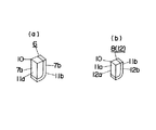
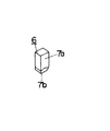
そして第一の射出装置2aから、粉末材料として超硬質材料が配合されている第一の成形材料4aを金型1に注入し、また第二の射出装置2bから、粉末材料としてニッケル合金が配合されている第二の成形材料4bを金型1に注入することにより射出成形を行い、第一の成形材料にて形成される部分7aと、第二の成形材料にて形成される部分7bという成分の異なる二種の部分からなる成形体6を成形するものである。ここで射出成形は、射出圧力1200kgf/cm2、金型内圧力750kgf/cm2、射出温度180℃、型内温度15℃の条件で行うことが好ましい。またここでこの成形体6は、図2(a)に示すように、切れ刃10を有する略四角状の刃物部11aを超硬質材料が配合されている第一の成形材料から成る部分7aで形成し、刃物部11aの切れ刃10を形成しない2辺に略L字型の接合部11bをニッケル合金が配合されている第二の成形材料から成る部分7bで形成して、刃先チップ12を製造するための成形体6として成形することができる。
【0026】
このようにして作製された成形体6は、脱脂工程において成形体6中の有機結合剤成分を除去する。すなわち例えば不活性雰囲気下で約500℃まで徐々に加熱して成形体6中の有機結合剤成分を除去するものである。
【0027】
そしてこのように有機結合剤が除去された成形体6を、例えば0.1〜1Torrの減圧下で1420℃で焼結させて図2(b)に示すような複合材料部品8を得る。このとき複合材料部品8は脱脂、焼結の過程において有機結合剤が失われるため、成形材料4中の粉末材料と有機結合剤との混練比率が上記のように体積比率で50:50であると、複合材料部品8は成形体6よりも約20%収縮するものである。このようにして得られる複合材料部品8は、成分の異なる二種以上の部分から構成されることとなる。特に上記のように成形体6を上記のように刃先チップ12を製造するための成形体6として成形した場合は、複合材料部品8は刃先チップ12として製造され、第一の材料粉末からなる部分(超硬質材料からなる部分)12aと第二の粉末材料からなる部分(ニッケル合金からなる部分)12bという成分の異なる二種の部分から構成されることとなる。
【0028】
このように粉末材料が配合された成分の異なる二種以上の成形材料4を、一つの金型1内に注入することにより射出成形を行うことにより、成分の異なる二種以上の部分からなる成形体6を成形するため、成形体6を複雑三次元形状に形成する場合でも射出成形により容易に成形することができるものである。従ってこのような成形体6を脱脂した後、焼結させて複合材料部品8を得るものとすると、成分の異なる二種以上の部分からなる複雑三次元形状の複合材料部品8を容易に製造することができるものである。
【0029】
本発明は、射出成形によって成形体6の成形を行う際、成形材料3を金型1内に注入する一つの射出ノズル3と、射出ノズル3に成形材料4を送る二以上のスクリュー13とを具備する射出装置2を用いることとしたものであり、このような射出装置2を用い、成分の異なる二種以上の成形材料4をそれぞれ各スクリューにより射出ノズル3に送り、射出ノズル3から成形材料4を金型1内に射出することによって、成分の異なる二種以上の成形材料4を、一つの金型1内に注入することにより成形体6の成形を行うこととしたものである。
【0030】
図3は参考例において用いる射出成形装置9の一例を示すものである。ここで金型1は、射出装置2の射出ノズル3が接続されるスプルーブッシュ5が一つのみ設けられたものが用いられる。また金型1内に成形材料4を注入する射出装置2としては、シリンダー14の先端に射出ノズル3を設けたものを使用することができる。シリンダー14の内部は、隔壁15により二つに仕切られて、第一のトラフ16a及び第二のトラフ16bが形成されており、それぞれのトラフ16a、16b内にはスクリュー13a、13bを配置すると共に、それぞれのトラフ16a、16b内に連通する貯槽17a、17bを設けるものである。ここでスクリュー13a,13bは棒材の周面に螺旋状の溝18を設けて形成するものであり、トラフ16a、16b内に軸回転自在、かつ軸方向にスライド移動自在に配置するものである。またシリンダー14内には、射出ノズル3とスクリュー13a、13bとの間に材料計量部19を設け、材料計量部19内に導入された成形材料4の重量を測定できるようにしている。
【0031】
上記のような射出成形装置9を用いて成形体6を成形する際は、まず図3(a)のようにスクリュー13a、13bを射出ノズル13a、13bと反対側にスライドさせた状態で、射出装置2の第一のトラフ16a内及び第二のトラフ16b内にそれぞれ連通する各貯槽17a、17bに、それぞれ第一の成形材料4a及び第二の成形材料4bを供給し、貯槽17a、17bから各トラフ16a、16b内に各成形材料4a、4bを供給する。そしてスクリュー13a、13bを軸回転させてトラフ16a、16b内の成形材料4a、4bを軸方向に射出ノズル3側に向けて移送し、材料計量部19に供給する。材料計量部19にて成形材料4a,4bの重量を計量した後、図3(b)に示すようにスクリュー13a、13bを射出ノズル3側に向けて軸方向にスライド移動させてスクリュー13a、13bの先端にて成形材料4a、4bを押し込み、成形材料4a、4bを射出ノズル3から、スプルーブッシュ5を介して金型1内に注入する。ここで金型1に注入する成形材料4a、4bは、材料計量部19にて計量されるため、金型1内に所定量の成形材料4a、4bを注入することができる。
【0032】
このようにして金型1内に第一の成形材料4aと第二の成形材料4bとを一つの金型1内に注入することにより、第一の成形材料から成る部分7aと第二の成形材料から成る部分7bという、成分の異なる二種の部分からなる成形体6を成形するものであり、その際、この成形体6を複雑三次元形状に形成する場合でも射出成形により容易に成形することができるものである。従ってこのような成形体6を脱脂した後、焼結させて複合材料部品8を得るものとすると、成分の異なる二種の部分からなる複雑三次元形状の複合材料部品8を容易に製造することができるものである。
【0033】
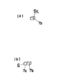
また、図3に示すような射出成形装置9を用いて成分の異なる二種の部分からなる成形体6を成形する場合、各成形材料4a、4bを金型1内に注入する際に、二つのスクリュー13a、13bを同時に射出ノズル3側に向けて軸方向にスライド移動させてスクリュー13a、13bの先端にて成形材料4a、4bを押し込むようにすると、第一の成形材料4aと第二の成形材料4bが共に同一のスプルーブッシュ5から同一方向に向けて同時に注入されるため、図4に示すような、成形材料4a、4bの注入方向に沿った面を中心にして一側に第一の成形材料からなる部分7a、他側に第二の成形材料からなる部分7bが分布した状態の成形体6を得ることができるものである。
【0034】
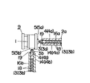
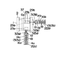
図5は本発明において用いる射出成形装置9の一例を示すものである。ここで金型1は、射出装置2の射出ノズル3が接続されるスプルーブッシュ5が一つのみ設けられたものが用いられる。また金型1内に成形材料4を注入する射出装置2としては、メインシリンダー21の先端に射出ノズル3を設けたものを使用することができる。メインシリンダー21の内部には材料計量部19を設け、材料計量部19内に導入された成形材料4の重量を測定できるようにしている。またメインシリンダー21内には軸方向にスライド移動自在なプランジャー20を配置するものである。またメインシリンダー21には、第一のサブシリンダー22aと第二のサブシリンダー22bとの二つのサブシリンダーを接続して設けるものである。ここで各サブシリンダー22a、22bの先端にはそれぞれ注入ノズル23a、23bを設けるものであり、この各サブシリンダー22a、22bの注入ノズル23a、23bをメインシリンダー22の材料計量装置19に接続して各サブシリンダー22a、22bの内部とメインシリンダー22の内部とを連通させるものである。また各サブシリンダー22a、22bの内部には、それぞれトラフ16a、16bが形成されており、各トラフ16a、16b内にはスクリュー13a、13を配置するものである。ここでスクリュー13a、13は棒材の周面に螺旋状の溝18を設けて形成するものであり、各トラフ16a、16b内に軸回転自在、かつ軸方向にスライド移動自在に配置するものである。
【0035】
上記のような射出成形装置9を用いて成形体6を成形する際は、まず図5(a)のようにメインシリンダー21内のプランジャー20を射出ノズル3と反対側にスライドさせた状態で、第一のサブシリンダー22aと第二のサブシリンダー22bの各トラフ16a、16b内に第一の成形材料4a及び第二の成形材料4bをそれぞれ供給し、スクリュー13a、13bを軸回転させて各トラフ16a、16b内の成形材料4a、4bを軸方向に注入ノズル23a、23b側に向けて移送し、注入ノズル23a、23bを介してメインシリンダー21の材料計量部19に供給する。材料計量部19にて成形材料4a、4bの重量を計量した後、図5(b)に示すようにプランジャー20を射出ノズル3側に向けて軸方向にスライド移動させてプランジャー20の先端にて成形材料4a、4bを押し込み、成形材料4a、4bを射出ノズル3から、スプルーブッシュ5を介して金型1内に注入する。ここで金型1に注入する成形材料4a、4bは、材料計量部19にて計量されるため、金型1内に所定量の成形材料4a、4bを注入することができる。このようにして金型1内に第一の成形材料4aと第二の成形材料4bとを一つの金型1内に注入することにより、図4に示すような、第一の成形材料から成る部分7aと第二の成形材料から成る部分7bという、成分の異なる二種の部分からなる成形体6を成形するものである。
【0036】
また、図5に示すような射出成形装置9を用いて成分の異なる二種の部分からなる成形体6を成形する場合は、第一の成形材料4aと第二の成形材料4bが共に同一のスプルーブッシュ5から同一方向に向けて同時に注入されるため、図4に示すような、成形材料4a、4bの注入方向に沿った面を中心にして一側に第一の成形材料からなる部分7a、他側に第二の成形材料からなる部分7bが分布した状態の成形体6を得ることができるものである。
【0037】
次の参考例は、射出成形によって成形体6の成形を行う際、各成形材料4a、4bを金型1内に注入する射出ノズル3a、3bと、射出ノズル3a、3bに成形材料4a、4bを送るスクリュー13a、13bとを具備する二つの射出装置2a、2bを用いることとしたものであり、このような二つの射出装置2a、2bを用い、成分の異なる二種の成形材料4a、4bをそれぞれ各射出装置2a、2bのスクリュー13a、13bにより射出ノズル3a、3bに送り、射出ノズル3a、3bから各成形材料4a、4bを金型1内に射出することによって、成分の異なる二種の成形材料4a、4bを、一つの金型1内に注入することにより成形体6の成形を行うこととしたものである。
【0038】
図6はこの参考例において用いる射出成形装置9の一例を示すものである。ここで金型1は、各射出装置2a、2bの射出ノズル3a、3bが二つ同時に接続されるスプルーブッシュ5が一つのみ設けられたものが用いられる。また金型1内に成形材料4a、4bを注入する射出装置2としては、第一の射出装置2aと第二の射出装置2bの二つのものを使用するものであり、各射出装置2a、2bとして、シリンダー14a、14bの先端に射出ノズル3a、3bを設けたものを使用するものである。また各シリンダー14a、14bの内部には、それぞれトラフ16a、16bが形成されており、トラフ16a、16b内にはそれぞれスクリュー13a、13bを配置するものである。ここでスクリュー13a、13bは棒材の周面に螺旋状の溝18を設けて形成するものであり、トラフ16a、16b内に軸回転自在、かつ軸方向にスライド移動自在に配置するものである。
【0039】
上記のような射出成形装置を用いて成形体6を成形する際は、各射出装置2a、2bのシリンダー14a、14b内のスクリュー13a、13bを射出ノズル3a、3bと反対側にスライドさせた状態で、第一の射出装置2aと第二の射出装置2bの各トラフ16a、16b内に第一の成形材料4a及び第二の成形材料4bをそれぞれ供給し、スクリュー13a、13bを軸回転させてトラフ16a、16b内の成形材料4a、4bを軸方向に射出ノズル3a、3b側に向けて移送し、材料計量部19に供給する。材料計量部19にて成形材料4a、4bの重量を計量した後、スクリュー13a、13bを射出ノズル3a、3b側に向けて軸方向にスライド移動させてスクリュー13a、13bの先端にて成形材料4a、4bを押し込み、成形材料4a、4bを射出ノズル3a、3bから、スプルーブッシュ5を介して金型1内に注入する。ここで金型1に注入する成形材料4a、4bは、材料計量部19にて計量されるため、金型1内に所定量の成形材料4a、4bを注入することができる。このようにして金型1内に第一の成形材料4aと第二の成形材料4bとを一つの金型1内に注入することにより、第一の成形材料から成る部分7aと第二の成形材料から成る部分7bという、成分の異なる二種の部分からなる成形体6を成形するものである。
【0040】
また、図6に示すような射出成形装置9を用いて成分の異なる二種の部分からなる成形体6を成形する場合、各成形材料4a、4bを金型1に注入する際に、二つのスクリュー13a、13bを同時に射出ノズル3a、3b側に向けて軸方向にスライド移動させてスクリュー13a、13bの先端にて成形材料4a、4bを押し込むようにすると、第一の成形材料4aと第二の成形材料4bが共に同一のスプルーブッシュ5から同一方向に向けて同時に注入されるため、図4に示すような、成形材料4a、4bの注入方向に沿った面を中心にして一側に第一の成形材料からなる部分7a、他側に第二の成形材料からなる部分7bが分布した状態の成形体6を得ることができるものである。
【0041】
図7は参考例において用いる射出成形装置9の他例を示すものである。ここで金型1は、射出装置2a、2bの射出ノズル3a、3bがそれぞれ一つづつ接続されるスプルーブッシュ5a、5bを二つ設けたものを用いる。また金型1内に成形材料4a、4bを注入する射出装置2a、2bとしては、シリンダー14a、14bの先端に射出ノズル3a、3bを設けた第一の射出装置2aと第二の射出装置2bの二つのものを使用するものである。この射出装置2a、2bとしては、図6に示すものと同様のものを用いることができる。
【0042】
上記のような射出成形装置9を用いて成形体6を成形する際は、金型1の一方のスプルーブッシュ5aに第一の射出装置2aの射出ノズル3aを接続すると共に、他方のスプルーブッシュ5bに第二の射出装置2bの射出ノズル3bを接続し、各射出装置2a、2bのシリンダー14a、14b内のスクリュー13a、13bを射出ノズル3a、3bと反対側にスライドさせた状態で、第一の射出装置2aと第二の射出装置2bの各トラフ16a、16b内に第一の成形材料4a及び第二の成形材料4bをそれぞれ供給し、スクリュー13a、13bを軸回転させてトラフ16a、16b内の成形材料4a、4bを軸方向に射出ノズル3a、3b側に向けて移送し、材料計量部19に供給する。材料計量部19にて成形材料4a、4bの重量を計量した後、スクリュー13a、13bを射出ノズル3a、3b側に向けて軸方向にスライド移動させてスクリュー13a、13bの先端にて成形材料4a、4bを押し込み、成形材料4a、4bを射出ノズル3a、3bから、各スプルーブッシュ5a、5bを介して金型1内に注入する。ここで金型1に注入する成形材料4a、4bは、材料計量部19にて計量されるため、金型1内に所定量の成形材料4a、4bを注入することができる。このようにして金型1内に第一の成形材料4aと第二の成形材料4bとを一つの金型1内に注入することにより、第一の成形材料から成る部分7aと第二の成形材料から成る部分7bという、成分の異なる二種の部分からなる成形体6を成形するものである。
【0043】
また、図7に示すような射出成形装置9を用いて成分の異なる二種の部分からなる成形体6を成形する場合、各成形材料4a、4bを金型1に注入する際に、二つのスクリュー13a、13bを同時に射出ノズル3a、3b側に向けて軸方向にスライド移動させてスクリュー13a、13bの先端にて成形材料4a、4bを押し込むようにすると、第一の成形材料4aと第二の成形材料4bが異なるスプルーブッシュ5a、5bから異なる方向に向けて同時に注入されるため、図8に示すような、二つのスプルーブッシュ5a,5bの配置位置からほぼ等距離の箇所に境界面を有し、この境界面について、各成形材料4a,4bからなる部分7a、12bが対称的に分布した状態の成形体6を得ることができるものである。
【0044】
また上記の図3、図6、及び図7に示す射出成形装置9を用いて成形体6を成形する際において、二つのスクリュー13a、13bをスライド移動させることによって、成形材料4a、4bを金型1内に注入する場合、各スクリュー13a、13bをスライド移動させるタイミングに時間差を設けることにより、成形体6中の二種類の各成形材料4a,4bからなる部分7a、7bの分布の状態を制御することができる。
【0045】
図9は、図3に示す射出成形装置9を用いる際に、各スクリュー13a、13bをスライド移動させるタイミングに時間差を設けた場合の一例を示すものである。この図9に示す例では、図9(a)に示すように材料計量部19に第一の成形材料4a及び第二の成形材料4bが供給された状態で、まず図9(b)に示すように第一の成形材料4aが供給されている第一のトラフ16a内のスクリュー13aを射出ノズル3の方向にスライド移動させて第一の成形材料4aを金型1に注入し、更に図9(c)に示すように、第二の成形材料4bが供給されている第二のトラフ16b内のスクリュー13bを射出ノズル3の方向へスライド移動させて第二の成形材料4を金型1に注入するものである。
【0046】
このように二種類の成形材料4a、4bを時間差を設けて射出することにより、スプルーブッシュ5の配置位置から離れた側とスプルーブッシュ5の配置位置から近い側のそれぞれに各成形材料4a、4bからなる部分が分布した成形体6を成形することができるものである。
【0047】
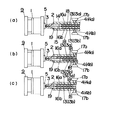
また図10は、図6に示す射出成形装置9を用いる際に、各スクリュー13a、13bをスライド移動させるタイミングに時間差を設けた場合の一例を示すものである。この図10に示す例では、二つの射出装置2a、2bの各材料計量部19にそれぞれ第一の成形材料4a及び第二の成形材料4bが供給された状態で、まず図10(a)に示すように第一の成形材料4aが供給されている第一の射出装置2a内のスクリュー13aを射出ノズル3aの方向にスライド移動させて第一の成形材料4aを金型1に注入し、更に図10(b)に示すように、第二の成形材料4bが供給されている第二の射出装置2b内のスクリュー13bを射出ノズル3aの方向へスライド移動させて第二の成形材料4bを金型1に注入するものである。
【0048】
このように二種類の成形材料4a、4bを時間差を設けて射出することにより、スプルーブッシュ5の配置位置から離れた側とスプルーブッシュ5の配置位置から近い側のそれぞれに各成形材料4a、4bからなる部分が分布した成形体6を成形することができるものである。
【0049】
また図11は、図6に示す射出成形装置9を用いる際に、各スクリュー13a、13bをスライド移動させるタイミングに時間差を設けた場合の一例を示すものである。この図11に示す例では、二つの射出装置2a、2bの各材料計量部19にそれぞれ第一の成形材料4a及び第二の成形材料4bが供給された状態で、まず図11(a)に示すように第一の成形材料4aが供給されている第一の射出装置2a内のスクリュー13aを射出ノズル3aの方向にスライド移動させて第一の成形材料4aを第一のスプルーブッシュ5aを介して金型1に注入し、更に図11(b)に示すように、第二の成形材料4bが供給されている第二の射出装置2b内のスクリュー13bを射出ノズル3bの方向へスライド移動させて第二の成形材料4bを第二のスプルーブッシュ5bを介して金型1に注入するものである。
【0050】
このように二種類の成形材料4a、4bを時間差を設けて射出することにより、図12に示すような、第二のスプルーブッシュ5bの近傍に、遅れて射出された第二の成形材料からなる部分7bが分布し、それ以外の部分に先に射出された第一の成形材料からなる部分7aが分布する成形体6を成形することができるものである。
【0051】
また上記のようにして二種類の成形材料4a、4bを時間差を設けて射出する際、図23に示すように、金型1として、切れ刃10を有する略四角状の刃物部11aの形状に対応する中空の第一のキャビティー29aと、略L字型の接合部11bの形状に対応する中空の第二のキャビティー29bを内部に備えるものを用いることができる。ここで、第二のキャビティー29bは、第一のキャビティー29aと接触して連通する位置に配置して設けるものである。また第二のキャビティー29bには第二のキャビティー29bの形状と同一の形状を有する占有片31をスライド移動自在に設けるものである。この占有片31は図23(a)のように第二のキャビティー29b内部を占有片31で全て占有する位置と、図23(b)のように第二のキャビティー29bと占有片31とがと接して第二のキャビティー29b内に占有片31が配置されない位置との間でスライド移動自在に設けるものである。また第一のキャビティー29aと第二のキャビティー29bは共にスプルーブッシュ5と接続するように配置するものであり、このとき各キャビティー29a、29bと成形材料4を供給する通路であるスプルー30は、図24(a)のように各キャビティー29a、29bの境界部に、各キャビティー29a、29bに亘って配置し、このときスプルー30からは第一のキャビティー29a側に第一の成形材料4aが,第二のキャビティー29b側に第二の成形材料4bがそれぞれ供給されるようにするものである。ここで、射出装置2からスプルーブッシュ5を介して金型1に注入される成形材料4は、上記のように第一の成形材料4aと第二の成形材料4bとが分離した状態で注入されるため、各キャビティー29a、29bの配置位置を調整することにより、スプルー30から第一のキャビティー29a側に第一の成形材料4aが,第二のキャビティー29b側に第二の成形材料4bがそれぞれ供給されるようにすることができるものである。
【0052】
そしてこのような金型1を用い、占有片31を図23(a)のように第二のキャビティー29b内部を占有片31で全て占有する位置に配置した状態で、まず射出装置2にて図24(b)のように第一の成形材料4aのみを金型1に注入して第一のキャビティー29aに第一の成形材料4aを注入する。第一の成形材料4aが第一のキャビティー29aに80%〜95%注入されたら、占有片31をスライド移動させて図23(b)のように第二のキャビティー29bと占有片31とが接して第二のキャビティー29b内に占有片31が配置されない位置に配置すると共に図24(c)のように射出装置2から金型1に第二の成形材料4bを注入し、第二のキャビティー29bに第二の成形材料4bが注入されるようにする。このとき第二の成形材料として第一の成形材料4aよりも流動性が高いものを用いると、第一のキャビティー29a内に注入されている第一の成形材料4a第二のキャビティー29bに流入する前に速やかに第二の成形材料4bを第二のキャビティー29b内に注入することができて、好ましい。このように第一の成形材料4a及び第二の成形材料4bを各キャビティー29a、29bに注入するようにすると、最終的に、図24(d)のように、第一のキャビティー29aに第一の成形材料4aが、第二のキャビティー29bに第二の成形材料4bが充填されて、成形体6が成形できる。このように成形された成形体6は、図2(a)に示すような、切れ刃10を有する略四角状の刃物部11aを超硬質材料が配合されている第一の成形材料から成る部分7aと、刃物部11aの切れ刃10を形成しない2辺に略L字型の接合部11bをニッケル合金が配合されている第二の成形材料から成る部分7bとで構成され、刃先チップ12を製造するための成形体6として成形されるものであり、この成形体6を脱脂した後焼結させることにより複合材料部品8を製造することにより、複合材料部品8を刃先チップ12として形成することができるものである。
【0053】
また二種以上の各成形材料4に配合される粉末材料の平均粒径、粒度分布、粒子形状、原材料比重や、各成形材料4に配合される有機結合剤の種類、あるいは成形材料4の組成比等を制御することによって、各成形材料4の流動性に差を持たせることにより、成形体6中の二種類以上の各成形材料4からなる部分の分布の状態を制御することができる。例えば第一の成形材料4aに配合される粉末材料として平均粒径が1μmの超硬質材料を用い、第二の成形材料4bに配合される粉末材料として平均粒径が10μmのニッケル合金を用いると、平均粒径が小さい粉末材料が配合されている第二の成形材料4aの流動性は第一の成形材料4bの流動性よりも高くなる。このように各成形材料4の流動性に差を設けた状態で、上記の図3、図5、図6又は図7に示す射出成形装置9を用いて第一の成形材料4aと第二の成形材料4bを同時に金型1に注入すると、図13(a)(b)に示すような、流動性がより高い第一の成形材料から成る部分7aが表層に分布し、流動性がより低い第二の成形材料からなる部分7bが内部に分布した状態の成形体6を得ることができる。
【0054】
別の参考例では、成形体6を成形する際に、まず第一の成形材料4aにてあらかじめ予備成形品6aを成形しておき、この予備成形品6aを本成形用の金型1b内に配置し、第二の成形材料4bをこの本成形用の金型1b内に注入することによって本成形を行って、成形体6を得るものである。
【0055】
図14はこの参考例に用いる射出成形装置9a,9bを示すものである。図14(a)は予備成形用の射出成形装置9aを示すものであり、スプルーブッシュ5を備える予備成形用の金型1aと、予備成形用の金型1aへ第一の成形材料4aを注入する第一の射出装置2aとを備えるものである。ここで第一の射出装置2aとしては、上記の図6、図7に示すものと同様のものを用いることができる。また図14(b)は本成形用の射出成形装置9bを示すものであり、スプルーブッシュ5を備え、内部に予備成形体6aを配置できる本成形用の金型1bと、本成形用の金型1bへ第二の成形材料4bを注入する第二の射出装置2bとを備えるものである。ここで第二の射出装置2bとしては、上記の図6、図7に示すものと同様のものを用いることができる。
【0056】
上記のような射出成形装置9a、9bを用いて成形体6を成形する際は、まず図14(a)に示すように、第一の射出装置2aの各材料計量部19に第一の成形材料4aが供給された状態で、第一の射出装置2a内のスクリュー13aを射出ノズル3aの方向にスライド移動させて第一の成形材料4aを予備成形用の金型1aに注入して、射出成形により図15(a)に示すような第一の成形材料からなる部分7aのみからなる予備成形体6aを成形する。そしてこの予備成形体6aを、図14(b)に示すように本成形用の金型1b内に配置して、第二の射出装置2bの材料計量部19に第二の成形材料4bが供給された状態で、第二の射出装置2b内のスクリュー13bを射出ノズル3bの方向にスライド移動させて第二の成形材料4bを本成形用の金型1bに注入して、図15(b)に示すような、第一の成形材料から成る部分7aと第二の成形材料から成る部分7bという、成分の異なる二種の部分からなる成形体6を成形するものであり、その際、この成形体6を複雑三次元形状に形成する場合でも射出成形により容易に成形することができるものである。従ってこのような成形体6を焼結させて複合材料部品8を得るものとすると、成分の異なる二種以上の部分からなる複雑三次元形状の複合材料部品8を容易に製造することができるものである。
【0057】
次の参考例は、成形体6を成形する際、内部に予備成形部23aと本成形部23bとを備え、金型内の成形品を予備成形部23aと本成形部23bとの間で移動させることができるスライド機構を具備する金型1を用いると共に、予備成形部23aに第一の成形材料4aを注入することができる第一の射出装置2a、及び本成形部23bに第二の成形材料4bを注入することができる第二の射出装置2bを用いるものであり、第一の射出装置2aを用いて第一の成形材料4aを予備成形部23aに注入することにより予備成形を行って予備成形体6aを成形し、この予備成形体6aをスライド機構にて本成形部23bに移動させ、第二の射出装置2bを用いて第二の成形材料4bを本成形部23bに注入することによって本成形を行うことにより成形体6を得るものである。
【0058】
図16乃至図18は参考例に用いる射出成形装置9を示すものである。ここで金型1内に成形材料4a、4bを注入する射出装置2a、2bとしては、シリンダー14a、14bの先端に射出ノズル3a、3bを設けた第一の射出装置2aと第二の射出装置2bの二つのものを使用するものである。この射出装置2a、2bとしては、図6に示すものと同様のものを用いることができる。また金型1としては、内部に予備成形部23a及び本成形部23bを備えると共に、第一の射出装置2a及び第二の射出装置2bの各射出ノズル3a、3bがそれぞれ接続される第一のスプルーブッシュ5a及び第二のスプルーブッシュ5bを設けたものを用いる。ここで第一のスプルーブッシュ5aは予備成形部23aに接続して設けると共に、第二のスプルーブッシュ5bは本成形部23bに接続して設けるものである。また本成形部23bには、成形体6の、予備成形体6aに相当する部分を除いた形状に対応する中空の第二のキャビティー29bを第二のスプルーブッシュ5bに接続して設けるものである。また金型1には所望の予備成形体6bの形状に対応するような形状に中空に形成された第一のキャビティー29aを備えるスライド体37を設けるものである。このスライド体37はエアーシリンダー等に接続してスライド移動自在に設けるものであり、第一のキャビティー29aが予備成形部23aと本成形部23bとの間で移動するように形成するものである。ここで第一のキャビティー29aは、予備成形部23aに配置されているときは第一のスプルーブッシュ5aに接続され、本成形部23bに配置されているときには第二のキャビティー29bに連通されるように形成するものである。
【0059】
上記のような射出成形装置9を用いて成形体6を成形する際は、金型1の予備成形部23aに接続されている第一のスプルーブッシュ5aに第一の射出装置2aの射出ノズル3aを接続すると共に、予備成形部23aに接続されている第二のスプルーブッシュ5bに第二の射出装置2bの射出ノズル3bを接続し、各射出装置2a、2bのシリンダー14a、14b内のスクリュー13a、13bを射出ノズル3a、3bと反対側にスライドさせた状態で、第一の射出装置2aと第二の射出装置2bの各トラフ16a、16b内に第一の成形材料4a及び第二の成形材料4bをそれぞれ供給する。そしてスクリュー13a、13bを軸回転させてトラフ16a、16b内の成形材料4a、4bを軸方向に射出ノズル3a、3b側に向けて移送し、材料計量部19に供給する。材料計量部19にて成形材料4a、4bの重量を計量した後、まず図16のようにスライド体37を第一のキャビティー29aが予備成形部23aに配置される位置に配置された状態で、第一の射出装置2aのスクリュー13aを射出ノズル3a側に向けて軸方向にスライド移動させてスクリュー13aの先端にて第一の成形材料4aを押し込み、第一の成形材料4aを射出ノズル3aから、第一のスプルーブッシュ5aを介して第一のキャビティー29aに注入し、射出成形により図15(a)に示すような第一の成形材料4aからなる部分7aのみからなる予備成形体6aを成形する。このように予備成形部23aにおいて成形された予備成形体6aを、図17のようにスライド体37をエアーシリンダー等により第一のキャビティー29aが本成形部23aに配置される位置までスライド移動させることにより本成形部23bに移動して本成形部23b内に予備成形体6aを配置し、この状態で図18のように第二の射出装置2b内のスクリュー13bを射出ノズル3bの方向にスライド移動させて第二の成形材料4bを第二のスプルーブッシュ5bを介して第二のキャビティー29bに注入して、図15(b)に示すような、第一の成形材料から成る部分7aと第二の成形材料から成る部分7bという、成分の異なる二種の部分からなる成形体6を成形するものであり、その際、この成形体6を複雑三次元形状に形成する場合でも射出成形により容易に成形することができるものである。従ってこのような成形体6を焼結させて複合材料部品8を得るものとすると、成分の異なる二種以上の部分からなる複雑三次元形状の複合材料部品8を容易に製造することができるものである。
【0060】
請求項2の発明は、粉末材料と有機結合剤とを配合して、二以上の成形材料4を調製する際、各成形材料4に、焼結温度が等しい粉末材料を配合するものである。
【0061】
具体的には、例えば第一の粉末材料を平均粒径0.8μmの、92wt%WC−8wt%Coや、94wt%WC−6wt%Co等の超硬合金とし、第二の粉末材料として、平均粒径2.5μmのニッケルを85wt%、平均粒径1.8μmのタングステンを15wt%含むニッケル合金を用いて、第一の粉末材料と第二の粉末材料の焼結温度をどちらも1420℃とし、このように調製した第一の粉末材料に、メタクリル酸ブチルエステル、メチレン−酢酸ビニル共重合体、パラフィンワックス、ステアリン酸等からなる有機結合剤(第一セラモ社製、「DC−1235」)を、第一の粉末材料と有機結合体の重量比が50:50となるように配合して第一の成形材料4aを調製すると共に、第二の粉末材料に同様の有機結合剤を第二の粉末材料と有機結合体の重量比が50:50となるように配合して第二の成形材料4bを調製し、上記の図3に示すような射出成形装置を用いて射出成形(二色成形)を行い、成形体6を得る。この成形体を約500℃まで徐々に加熱して有機結合剤を除去し、0.1〜1Torrの減圧下、1420℃で二時間加熱して焼結させて、複合材料部品8を得る。
【0062】
このようにすると、成形体6を構成する二以上の各成形材料4からなる部分の焼結温度が等しくなるため、成形体6を炉中で加熱して焼結させることができ、成分の異なる二種以上の部分からなる複雑三次元形状の複合材料部品8の量産を容易に行うことができるものである。また上記のように第二の粉末材料としてニッケル合金を用いて複合材料部品8を製造するものとすると、この複合材料部品8を例えば切削工具の刃先チップ12として用いる際、下記において詳述するように、SK5のような工具鋼で作製された台金24との接合面に複合材料部品8のニッケル合金からなる部分を配置し、この両者の接合面の近傍に高エネルギービーム等を照射して、鉄系材料と超硬合金を溶接するレーザー溶接法により刃先チップ12と台金24とを接合することができ、従来のように刃先チップ12と台金24との接合面にニッケル合金等の金属片を挿入する必要がなく、接合工程を簡略化することができるものである。
【0063】
請求項3の発明は、粉末材料と有機結合剤とを配合して、二以上の成形材料4を調製する際、各成形材料4を、焼結温度が異なる各粉末材料を用いてそれぞれ調製し、この成形材料4にて成形した成形体6を焼結させる際、各粉末材料の焼結温度のうち最も低い焼結温度よりも低い温度で仮焼結を行い、その後本焼結を行うことにより複合材料部品8を得るものである。ここで仮焼結を行う際の好適な焼結温度の範囲は、用いる成形材料4によって変動するものであるが、焼結温度が最も低い成形材料4の焼結温度よりも200〜500℃だけ低い温度とすることが好ましく、下記のように第一の粉末材料を92wt%WC−8wt%Coや、94wt%WC−6wt%Co等の超硬合金、第二の粉末材料を純ニッケルとする場合は仮焼結を900℃〜1100℃で行うのが好ましいものである。
【0064】
例えば第一の粉末材料を92wt%WC−8wt%Coや、94wt%WC−6wt%Co等の超硬合金とする場合、第二の粉末材料を純ニッケルとして、第一の粉末材料の焼結温度を1420℃、第二の粉末材料の焼結温度を1370℃とする。このように調製した第一の粉末材料に有機結合剤(第一セラモ社製、「DC−1235」)を配合して第一の成形材料4aを調製すると共に、第二の粉末材料に有機結合剤(第一セラモ社製、「DC−1235」)を配合して第二の成形材料4bを調製し、上記の図3、図5、図6、図7、図14、及び図16乃至図18に示すような射出成形装置9を用いて射出成形(二色成形)を行い、成形体6を得る。この成形体6を約500℃まで徐々に加熱して有機結合剤を除去し、次いで、真空中でニッケルの焼結温度よりも低い温度である1000℃で加熱して成形体6を仮焼結させて、仮焼結体を得る。この仮焼結体を、放電プラズマ焼結等により本焼結させて複合材料部品8を得る。
【0065】
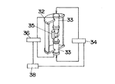
ここでプラズマ焼結法は、図25に示すようなプラズマ焼結装置を用いて行うことができる。このプラズマ焼結装置は、中空の円柱状の水冷真空チャンバー32に両端からそれぞれ押圧ダイ33を、各押圧ダイ33の端部が水冷真空チャンバー32内で対向するように挿通させてスライド移動自在に設けたものである。また各押圧ダイ33の端部はそれぞれ水冷真空チャンバー32内に配置された円筒状の焼結ダイ35の各端部に挿通させるものである。ここで成形体6は焼結ダイ35内に配置され、各押圧ダイ33からの押圧力にて加圧されるものである。またこのプラズマ焼結装置には、水冷真空チャンバー32に接続される真空ポンプ(図示せず)、押圧ダイ33間に直流電流またはパルス電流を印加する電源36、及び各押圧ダイ33に圧力をかける加圧機構34を備えると共に、電源36にて押圧ダイ33間に印加する電流及び加圧機構34にて各押圧ダイ33にかける加圧力を制御する制御系38を備えるものである。
【0066】
このようなプラズマ焼結装置を用いて成形体6のプラズマ焼結を行うにあたっては、まず成形体6を焼結ダイ35中に配置し、真空ポンプにて水冷真空チャンバー32内を0.1〜1Torrに減圧した状態で加圧機構34にて押圧ダイ33を加圧して成形体6を両側から押圧ダイ33にて押圧して200〜300kgf/cm2の圧力をかけると共に、押圧ダイ33間に電源36にて直流電流またはパルス電流を印加して成形体6が1300℃になるように通電加熱する。このようにして成形体6を5〜20分間加熱・加圧することによって成形体6を焼結させ、複合材料部品8を得るものである。
【0067】
このようにすると、成形体6を構成する二以上の各成形材料4からなる部分の焼結温度が異なって炉中で焼結させることが困難な場合でも成形体6を焼結させることができ、成分の異なる二種以上の部分からなる複雑三次元形状の複合材料部品8を製造することができるものである。
【0068】
請求項4の発明は、粉末材料と有機結合剤とを配合して、二以上の成形材料4を調製する際、各粉末材料のうち少なくとも一つのものとして超硬質材料を用い、超硬質材料以外の他の粉末材料として展延性に富む材料を用いるものである。この展延性に富む材料としては、断面形状が1×2mmの方形である棒材に形成した試料についてJIS Z2241に基づく引張試験を行った際の試料の伸びが20%以上のものを用いることが好ましい。展延性は高ければ高いほど好ましいものであるが、特に上限を設けるとすると、上記の引張試験を行った際の試料の伸びが50%とするものであり、50%もあれば充分所望の効果が得られるものである。
【0069】
例えば第一の粉末材料を92wt%WC−8wt%Coや、94wt%WC−6wt%Co等の超硬合金とする場合、第二の粉末材料をJIS Z2241に基づく引張試験を行った際の試料の伸びが25%であるニッケル合金や、30%である純ニッケルとして、このように調製した第一の粉末材料に有機結合剤を配合して第一の成形材料4aを調製すると共に、第二の粉末材料に有機結合剤を配合して第二の成形材料4bを調製し、上記の図3、図5、図6、図7、図14、及び図16乃至に示すような射出成形装置9を用いて射出成形(二色成形)を行い、成形体6を得る。この成形体6を脱脂した後焼結させて複合材料部品8を得る。
【0070】
このようにすると、成形体6を加熱して焼結させる際、焼結時の成形体6中の粉末材料が熱膨張し、また加熱終了後に冷却された際に熱収縮する場合に、成形体6中の超硬質材料からなる部分とそれ以外の部分との境界面において剥離が生じたり、超硬質材料以外の部分が割れたりすることを、成形体6の超硬質材料以外の部分に含まれる展延性に富む材料の弾性変形により防止することができるものであり、成分の異なる二種以上の部分からなる複雑三次元形状の複合材料部品8を容易に製造することができるものである。
請求項5の発明は、粉末材料と有機結合剤とを配合して、二種類の成形材料4を調製する際、第一の粉末材料として超硬質材料を用い、第二の粉末材料としてニッケル又はニッケル合金を用いるものである。具体的には、例えば第一の粉末材料を平均粒径0.8μmの92wt%WC−8wt%Coや、94wt%WC−6wt%Co等の超硬合金とし、第二の粉末材料として、平均粒径2.5μmのニッケルを85wt%、平均粒径1.8μmのタングステンを15wt%含むニッケル合金を用いるものである。そして第一の粉末材料に有機結合剤を配合して第一の成形材料4aを調製すると共に、第二の粉末材料に有機結合剤を配合して第二の成形材料4bを調製し、上記の図3に示すような射出成形装置を用いて射出成形(二色成形)を行い、成形体6を得る。この成形体6を約500℃まで徐々に加熱して有機結合剤を除去し、0.1〜1Torrの減圧下、1420℃で二時間加熱して焼結させて、複合材料部品8を得る。
【0071】
このようにすると、上記のようにニッケル又はニッケル合金は展延性に富むため、二種類の成形材料4a、4bを用いて成形体6を成形する際、第二の粉末材料としてニッケル又はニッケル合金が配合された第二の成形材料4bを用いると、成形体6を加熱して焼結させる際、焼結時の成形体6中の粉末材料が熱膨張し、また加熱終了後に冷却された際に熱収縮する場合に、成形体6中の第一の成形材料からなる部分7aと第二の成形材料からなる部分7bとの境界面において剥離が生じたり、第二の成形材料からなる部分7bが割れたりすることを、第二の成形材料からなる部分7bに含まれる展延性に富むニッケル又はニッケル合金の弾性変形により防止することができるものであり、成分の異なる二種の部分からなる複雑三次元形状の複合材料部品8を容易に製造することができるものである。また上記のように第二の粉末材料としてニッケル合金を用いて複合材料部品8を製造するものとすると、この複合材料部品8を例えば切削工具の刃先チップ12として用いる際、下記において詳述するようにSK5のような工具鋼で作製された台金24との接合面に複合材料部品8のニッケル合金からなる部分を配置し、この両者の接合面の近傍に高エネルギービーム等を照射して、鉄系材料と超硬合金を溶接するレーザー溶接法により刃先チップ12と台金24とを接合することができ、従来のように刃先チップ12と台金24との接合面にニッケル合金等の金属片を挿入する必要がなく、接合工程を簡略化することができるものである。
【0072】
請求項6の発明は、セラミック粉末及び金属粉末から選択された少なくとも一種以上のものからなる粉末材料と、有機結合剤とを混練することにより、成分の異なる二種以上の成形材料4を調製し、この二種以上の成形材料4の射出成形を行うことにより成分の異なる二種以上の部分からなる成形体6を成形し、この成形体6を脱脂した後焼結させることによって得られる複合材料部品8である。これは既述の複合材料部品8の製造方法によって製造される複合材料部品8である。
【0073】
請求項6の発明は、粉末材料と有機結合剤とを配合して、二種の成形材料4a、4bを調製する際、第一の粉末材料として超硬質材料を用い、第二の粉末材料として易溶接性材料を用い、このような二種の成形材料4a、4bを用いて射出成形により成形体6を成形し、この射出成形の際、切れ刃10を有する刃物部11aを超硬質材料で成形し、台金24との接合部11bを有する部分を易溶接性材料で成形することによって成形し、この成形体6を脱脂した後焼結させることによって得られる複合材料部品8であり、この複合材料部品8を切削工具の刃先チップ12とするものである。
【0074】
この複合材料部品8は、既述の複合材料部品8の製造方法にて製造するものであるが、射出成形により成形体8を成形する際に、図2(a)に示すように、切れ刃10を有する略四角状の刃物部11aを超硬質材料が配合されている第一の成形材料から成る部分7aで形成し7刃物部11aの切れ刃10を形成しない2辺に略L字型の接合部11bをニッケル合金が配合されている第二の成形材料から成る部分7bで形成するものである。そしてこのようにして成形された成形体6を脱脂した後焼結させることによって図2(b)に示すような、第一の材料粉末からなる部分(超硬質材料からなる部分)12aで形成される刃物部11aと、第二の粉末材料からなる部分(ニッケル合金からなる部分)12bで形成される接合部11bという成分の異なる二種の部分から構成され、刃先チップ12として形成される複合材料部品を得ることができるものである。
【0075】
図19は刃先チップ12として製造された請求項6の複合材料部品8を台金24に接合する様子を示すものである。台金24は例えば丸鋸刃等の切削工具の本体として形成するものであり、SK5のような工具鋼などの金属板をプレス加工等して、外周に多数の被接合部25を設けて形成するものである。被接合部25は台金24の外周に突接された突片26の入隅部に略L字型に形成されるものである。台金24の各被接合部25に刃先チップ12を接合するにあたっては、台金24の被接合部25と刃先チップ12の接合部11bを重ね、台金24の被接合部25の近傍において両側から高エネルギービームを照射する。高エネルギービームとしては、レーザーや電子ビームを用いることができる。このように台金24の被接合部25近傍に高エネルギービームを照射すると、台金24の高エネルギービームが照射された部分が加熱されると共に、この熱でその近傍に設置したニッケル合金で構成される接合部11bが加熱される。そしてニッケル合金で構成される接合部11bが溶融すると共にニッケルが台金24や刃先チップ12の刃物部11a内に拡散し、接合部11bのニッケル合金の溶融固化層及び台金24や刃物部11a中のニッケル拡散合金層によって台金24に刃先チップ12を接合することができるものである。
【0076】
上記のように、刃先チップ12として形成される請求項6の複合材料部品8を台金24に接合する際は、高エネルギービームによる溶接により接合を行うことができるものであり、このようにして高エネルギービームによる溶接により台金24に刃先チップ12としての複合材料部品8を接合すると、高エネルギービームは台金24に照射するため、刃先チップ12が高エネルギービームによって急加熱されることがなくなり、刃先チップ12の刃物部11aを靭性の低い超硬質材料で形成しても、熱衝撃で刃先チップ12に割れが生じるということを未然に防ぐことができるものである。またはニッケル合金で構成される接合部11bと超硬質材料で構成される刃物部11aとが一体となって刃先チップ12が形成されているため、刃先チップ12を台金24に高エネルギービームにて溶接することにより接合する際に、刃先チップ12と台金24との接合面に金属片を挿入する必要がなく、接合工程を簡略にすることができるものである。またこの刃先チップ12としての複合材料部品8を製造する場合、上記のように粉末材料から成形体6を成形する際に、第一の粉末材料として超硬質材料が配合された第一の成形材料4aと、第二の粉末材料として易溶接性材料が配合された第二の成形材料4bという、成分の異なる二種の成形材料4a、4bを、一つの金型1内に注入することにより射出成形を行うことにより、超硬質材料を含む第一の成形材料からなる部分7aと、易溶接性材料を含む第二の成形材料からなる部分7bという、成分の異なる二種以上の部分からなる成形体6を成形することができるものであり、その際、この成形体6を複雑三次元形状に形成する場合でも射出成形により容易に成形することができるものである。従ってこのような成形体6を焼結させて得られる複合材料部品8は、超硬質材料からなる刃物部11aと、易溶接性材料からなる接合部11bという、成分の異なる二種の部分からなる複雑三次元形状の複合材料部品8として容易に製造することができるものであり、複合材料部品8を種々の形状を有する刃先チップ12として容易に形成することができるものである。
【0077】
請求項6の複合材料部品8の他の例としては、図20に示すものがある。この図20に示す複合材料部品8は、刃先チップ12の刃物部11aの先端の両側にそれぞれ切れ刃10a、10bを突出させて設けた刃先チップ12として形成したものである。本発明においてはこのように複雑三次元形状の複合材料部品8を容易に製造することができる。このような刃先チップ8を台金24に接合して作製される切削工具を用いると、切削工具で木材を切断する場合に、ケバなどの切り残しが出ない綺麗な切断が可能になるものである。
【0078】
すなわち、図21は切れ刃10を一つだけ設けた刃先チップ12を台金24に接合して形成した切削工具で木材27を切断する様子を示すものであり、図21の(a)、(b)、(c)、(d)、の順に切断が進行するが、切れ刃10が一つの刃先チップ12では図21(d)のようにケバ28などの切り残しが生じやすい(切断方向を矢印で示す)。一方図22は切れ刃10a、10bを先端の両側に二個設けた刃先チップ12を台金24に接合して形成した切削工具で木材27を切断する様子を示すものであり、図22の(a)、(b)の順に、切断が進行するが、ケバ28などの切り残しは生じない(切断方向を矢印で示す)。
【0079】
【発明の効果】
上記のように本発明の請求項1に記載の複合材料部品の製造方法は、セラミックス粉末及び金属粉末から選択された一種以上の粉末材料と有機結合剤とを混練して超硬質材料を配合した成形材料と易溶接性材料を配合した成形材料とを調製し、成形材料を金型内に注入する一つの射出ノズルが設けられると共に内部にプランジャーが配置されたメインシリンダーに二つのサブシリンダーが接続され、且つ各サブシリンダーの内部のトラフにスクリューが配置された射出装置を用いて、各サブシリンダーの各トラフ内に成形材料をそれぞれ供給し、各スクリューを軸回転させて各トラフ内の成形材料をメインシリンダーに供給し、プランジャーを射出ノズル側に向けて移動させてプランジャーの先端にて成形材料を押し込み、射出ノズルから成形材料を金型内に射出することによって、成分の異なる二種以上の成形材料を、金型内に注入することにより射出成形を行って、超硬質材料を配合した成形材料で切れ刃を有する刃物部となる部分を成形し、易溶接性材料を配合した成形材料で台金と接合される接合部となる部分を成形した成形体を成形し、この成形体を脱脂した後焼結させることによって切削工具の刃先チップとして形成するため、超硬質材料を含む第一の成形材料からなる部分と、溶接性材料を含む第二の成形材料からなる部分という、成分の異なる二種以上の部分からなる成形体を成形することができるものであり、その際、この成形体を複雑三次元形状に形成する場合でも射出成形により容易に成形することができるものであり、このような成形体を焼結させることにより、超硬質材料からなる刃物部と、溶接性材料からなる接合部という、成分の異なる二種以上の部分からなる複雑三次元形状の複合材料部品を容易に製造することができるものであり、複合材料部品を種々の形状を有する刃先チップとして形成することができるものである。また作製された複合材料部品を台金に接合する際は、高エネルギービームによる溶接により接合を行うことができるものであり、刃先チップが高エネルギービームによって急加熱されることがなくなり、刃先チップの刃物部を靭性の低い超硬質材料で形成しても、熱衝撃で刃先チップに割れが生じるということを未然に防ぐことができるものである。またこの接合の際に、刃先チップと台金との接合面に金属片を挿入する必要がなく、接合工程を簡略にすることができるものである。
【0084】
また本発明の請求項2に記載の複合材料部品の製造方法は、二種以上の成形材料を調製するにあたって、各成形材料を、焼結温度が等しい粉末材料を用いてそれぞれ調製して成るため、成形体を構成する二以上の各成形材料からなる部分の焼結温度を等しくすることができ、成形体を炉中で加熱して焼結させることができて、セラミックス、金属等からなる成分の異なる二種以上の部分からなる複雑三次元形状の複合材料部品の量産を容易に行うことができるものである。
【0085】
また本発明の請求項3に記載の複合材料部品の製造方法は、二種以上の成形材料を調製するにあたって、各成形材料を、焼結温度が異なる各粉末材料を用いてそれぞれ調製し、成形体を焼結させる際、各粉末材料の焼結温度のうち最も低い焼結温度よりも低い温度で仮焼結を行い、その後本焼結を行うことにより複合材料部品を得るため、成形体を構成する二以上の各成形材料からなる部分の焼結温度が異なって炉中で焼結させることが困難な場合でも成形体を焼結させることができ、セラミックス、金属等からなる成分の異なる二種以上の部分からなる複雑三次元形状の複合材料部品を容易に製造することができるものである。
【0086】
また本発明の請求項4に記載の複合材料部品の製造方法は、各粉末材料のうち少なくとも一つのものが超硬質材料であり、他のものが展延性に富む材料であるため、成形体を加熱して焼結させる際、焼結時の成形体中の粉末材料が熱膨張し、また加熱終了後に冷却された際に熱収縮する場合に、成形体中の超硬質材料からなる部分とそれ以外の部分との境界面において剥離が生じたり、超硬質材料以外の部分が割れたりすることを、成形体の超硬質材料以外の部分に含まれる展延性に富む材料の弾性変形により防止することができるものであり、セラミックス、金属等からなる成分の異なる二種以上の部分からなる複雑三次元形状の複合材料部品を容易に製造することができるものである。
【0089】
また本発明の請求項5に記載の複合材料部品の製造方法は、第一の粉末材料として超硬質材料を用い、第二の粉末材料としてニッケル又はニッケル合金を用いるため、成形体を加熱して焼結させる際、焼結時の成形体中の粉末材料が熱膨張し、また加熱終了後に冷却された際に熱収縮する場合に、成形体中の超硬質材料からなる部分とそれ以外の部分との境界面において剥離が生じたり、超硬質材料以外の部分が割れたりすることを、成形体の超硬質材料以外の部分に含まれる展延性に富むニッケル又はニッケル合金の弾性変形により防止することができるものであり、セラミックス、金属等からなる成分の異なる二種の部分からなる複雑三次元形状の複合材料部品を容易に製造することができるものである。
【図面の簡単な説明】
【図1】 参考例において用いる射出成形装置の一例を示す一部破断した平面図である。
【図2】 (a)は本発明において成形される成形体の一例を示す斜視図、(b)は(a)の成形体から作製される複合材料部品を示す斜視図である。
【図3】 (a),(b)は、参考例において用いる射出成形装置の他の例の動作を示す一部破断した平面図である。
【図4】 本発明において成形される成形体の他の例を示す斜視図である。
【図5】 (a),(b)は、本発明において用いる射出成形装置の一例の動作を示す一部破断した平面図である。
【図6】 参考例において用いる射出成形装置の更に他の例を示す一部破断した平面図である。
【図7】 参考例において用いる射出成形装置の更に他の例を示す一部破断した平面図である。
【図8】 本発明において成形される成形体の更に他の例を示す斜視図である。
【図9】 (a)乃至(c)は図3に示す射出成形装置の他の動作を示す一部破断した平面図である。
【図10】 (a),(b)は図6に示す射出成形装置の他の動作を示す一部破断した平面図である。
【図11】 (a),(b)は図7に示す射出成形装置の他の動作を示す一部破断した平面図である。
【図12】 本発明において成形される成形体の更に他の例を示す斜視図である。
【図13】 (a)は本発明において成形される成形体の更に他の例を示す斜視図、(b)は(a)の断面図である。
【図14】 参考例において使用する射出成形装置の更に他の例を示すものであり、(a)は予備成形用の射出成形装置を示す一部破断した平面図、(b)は本成形用の射出成形装置を示す一部破断した平面図である。
【図15】 (a)は参考例において成形される予備成形体の一例を示す斜視図、(b)は(a)の予備成形体を本成形することによって成形される成形体を示す斜視図である。
【図16】 参考例において使用する射出成形装置の更に他の例の、一段階目の動作を示す一部破断した平面図である。
【図17】 参考例において使用する射出成形装置の更に他の例の、二段階目の動作を示す一部破断した平面図である。
【図18】 参考例において使用する射出成形装置の更に他の例の、三段階目の動作を示す一部破断した平面図である。
【図19】 本発明の刃先チップとして形成した複合材料部品を台金に接合する様子を示す斜視図である。
【図20】 本発明の刃先チップとして形成した複合材料部品の他の例を示す斜視図である。
【図21】 (a)乃至(d)は、切れ刃が一つの切削工具による木材の切断の状態を示す図である。
【図22】 (a),(b)は切れ刃が二つの切削工具による木材の切断の状態を示す図である。
【図23】 (a)、(b)は第一のキャビティーと第二のキャビティーを示す斜視図である。
【図24】 (a)乃至(d)は、図23の第一のキャビティーと第二のキャビティーへの成形材料の注入の過程を示す概略図である。
【図25】 プラズマ装置の一例を示す一部破断した斜視図である。
【符号の説明】
1 金型
1b 本成型用の金型
2 射出装置
2a 第一の射出装置
2b 第二の射出装置
3 射出ノズル
4 成形材料
4a 第一の成形材料
4b 第二の成形材料
6 成形体
6b 予備成形体
8 複合材料部品
10 切れ刃
11a 刃物部
11b 接合部
12刃先チップ
13 スクリュー
23a 予備成形部
23b 本成形部
24 台金[0001]
BACKGROUND OF THE INVENTION
The present invention relates to a method for producing a composite material part comprising two or more kinds of metal or ceramic materials.To the lawIt is related.
[0002]
[Prior art]
Cutting tools for cutting metals, plastics, ceramics materials, etc., for example, base metal made of tool steel such as SK5, SKH (high speed tool) steel and superHardIt is produced by joining blade tips made of an alloy. At this time, as a method of joining the base metal and the cutting edge tip,UBrazing using solder has often been used, but since brazing uses flux, maintenance such as cleaning must be performed frequently, and this flux adheres to jigs and the like, resulting in poor bonding accuracy. There was also a problem. Further, in this brazing, since a high heat is applied over a considerably wide range in the vicinity of the joint portion, a cutting edge tip made of a base metal made of SK5 or the like tempered by heat treatment or SKH (high speed tool) is used. There was also a problem that the hardness and rigidity were lowered by annealing.
[0003]
Recently, a joining method that joins a base metal made of an iron-based material and a cutting edge tip made of a cemented carbide with a high-energy beam has been developed as a joining method that replaces the joining method by brazing. However, when welding iron-based materials and cemented carbide, the difference in coefficient of linear expansion between the two is large, so thermal stress occurs during joining, and this thermal stress causes cracks in the joint and cemented carbide. There is a case.
[0004]
For this reason, when joining ferrous materials and cemented carbide, insert a metal piece such as nickel or copper between the joints between them and irradiate the vicinity of the insertion surface with a high-energy beam, thereby They are joined by welding alloys.
[0005]
However, in the joining method by welding using the metal piece as described above, the metal piece has to be inserted between the joints, and there is a drawback that the joining process becomes complicated. In order to solve such a problem, a composite material part in which a cutting edge tip and a metal piece are integrated is required.
[0006]
Here, as a method for producing a composite part of a metal and a ceramic material, each powder material is alternately filled in a mold as disclosed in Japanese Patent Laid-Open No. 62-30804. There is one that is manufactured by sintering by an electric heating sintering method.
[0007]
[Problems to be solved by the invention]
However, in the composite material manufacturing method as described above, it is not possible to manufacture a composite material having a simple shape that can be hot-pressed or electro-heated and sintered. It was difficult to manufacture.
[0008]
The present invention has been made in view of the above points, and is a method for manufacturing a composite material part having a complex three-dimensional shape composed of two or more different parts made of metal or ceramics.The lawIt is intended to provide.
[0009]
[Means for Solving the Problems]
According to a first aspect of the present invention, there is provided a method for manufacturing a composite material component comprising: kneading one or more powder materials selected from ceramic powder and metal powder and an organic binder.Molding material 4 blended with super hard material and molding material 4 blended with easily weldable materialPrepared,One injection nozzle for injecting the molding material 4 into the mold is provided, and two sub cylinders are connected to the main cylinder in which the plunger is arranged, and a screw is arranged in the trough inside each sub cylinder. The injection device is used to supply the molding material into each trough of each sub-cylinder, the shafts of each screw are rotated to supply the molding material 4 in each trough to the main cylinder, and the plunger is moved to the injection nozzle side. The molding material 4 is pushed in at the tip of the plunger, and the molding material is injected into the mold from the injection nozzle, thereby injecting two or more molding materials having different components into the mold.Injection moldingThe part that becomes the blade part having the cutting edge is molded with the molding material 4 blended with the super hard material, and the part that becomes the joint part to be joined with the base metal is molded with the molding material 4 blended with the easily weldable material.Molding the molded body, degreasing the molded body and then sinteringBy forming as cutting edge tip of cutting toolA method of manufacturing a composite material part characterized by the above.
[0014]
Claims of the invention2A method for manufacturing a composite material part according to claim1'sIn addition to the configuration, when preparing two or more kinds of molding materials 4, each molding material 4 is prepared using each powder material having the same sintering temperature.
[0015]
Claims of the invention3A method for manufacturing a composite material part according to claim 1 is as follows.Or 2In addition to the configuration, when preparing two or more types of molding materials 4, each molding material 4 is prepared using each powder material having a different sintering temperature, and when the compact 6 is sintered, each powder material is prepared. The composite material part 8 is obtained by performing preliminary sintering at a temperature lower than the lowest sintering temperature among the sintering temperatures, followed by main sintering.
[0016]
Claims of the invention4The method of manufacturing a composite material part according to claim 1,3In addition to any one of the structures, at least one of the powder materials used when preparing two or more types of molding material 4 is an ultra-hard material, and the other is a material having high extensibility. It is a feature.
[0017]
Claims of the invention5The method of manufacturing a composite material part according to claim 1,4In addition to any of the above structures, a super hard material is used as the first powder material, and nickel or a nickel alloy is used as the second powder material.
[0020]
DETAILED DESCRIPTION OF THE INVENTION
Embodiments of the present invention will be described below.
[0021]
powderAs a powder material, two or more molding materials 4 having different components are prepared using a mixture of at least one selected from ceramic powder and metal powder, and the molding material 4 is placed in one mold 1. Injection molding is performed to form a molded body 6 composed of two or more parts having different components, and the molded body 6 is composed of two or more parts having different components by degreasing and then sintering. The composite material part 8 to be obtained is obtained. The average particle size of the powder material is preferably 1 to 10 μm. At this time, the linear expansion coefficients of the respective powder materials are preferably as close as possible.
[0022]
Specifically, for example, as the first powder material,A WC-Co based cemented carbide may be used, and a metal material such as SKH57 or SKD11, or a ceramic material such as alumina or zirconia may be used. AlsoAs the second powder material, 85 wt% nickel-15 wt% tungsten alloy (hereinafter referred to as nickel alloy) or the like can be used, and the composite material part 8 can be manufactured using these two kinds of powder materials.
[0023]
Such a powder material and an organic binder (powder injection molding binder) are blended and kneaded to obtain the molding material 4. At this time, the kneading ratio of the powder material and the organic binder is preferably 50:50 in volume ratio in any molding material 4, and the shrinkage ratio after sintering of each molding material 4 is preferably made equal. Here, as the organic binder, an organic vinyl acetate copolymer (EVA), polybutyl methacrylate, stearic acid, paraffin wax, or the like can be used. For example, “DC-1235” manufactured by Daiichi Ceramo Co., Ltd. Can be used.
[0024]
The molding 7 is molded by injecting the molding material 4 thus prepared into one mold 1 and injection molding. At this time, FIG.Reference exampleAs shown in FIG. 3, an injection molding apparatus 9 including a mold 1, a first injection apparatus 2a, and a second injection apparatus 2b can be used. Here, a sprue bush 5 for injecting a molding material 4 into the mold 1 is formed in the mold 1, and the first injection device 2 a and the second injection device 2 b are connected via the sprue bush 5. The molding material 4 is injected into the mold 1.
[0025]
Then, a first molding material 4a containing a super hard material as a powder material is injected into the mold 1 from the first injection device 2a, and a nickel alloy is added as a powder material from the second injection device 2b. Injection molding is performed by injecting the second molding material 4b that has been used into the mold 1, and a portion 7a formed of the first molding material and a portion 7b formed of the second molding material are referred to. A molded body 6 composed of two parts having different components is molded. Here, the injection molding is performed with an injection pressure of 1200 kgf / cm.2, Mold internal pressure 750kgf / cm2The injection temperature is preferably 180 ° C. and the mold temperature is 15 ° C. In addition, as shown in FIG. 2 (a), the molded body 6 is a portion 7a made of a first molding material in which a super-hard material is mixed with a substantially square blade portion 11a having a cutting edge 10. The cutting edge 10 of the blade part 11a is formed, and a substantially L-shaped joining part 11b is formed on two sides of the cutting part 10a by a part 7b made of a second molding material in which a nickel alloy is blended, and the cutting edge tip 12 is formed. It can shape | mold as the molded object 6 for manufacturing.
[0026]
Thus, the produced molded object 6 removes the organic binder component in the molded object 6 in a degreasing process. That is, for example, the organic binder component in the molded body 6 is removed by gradually heating to about 500 ° C. in an inert atmosphere.
[0027]
Then, the molded body 6 from which the organic binder has been removed is sintered at 1420 ° C. under a reduced pressure of, for example, 0.1 to 1 Torr to obtain a composite material part 8 as shown in FIG. At this time, since the organic binder is lost in the process of degreasing and sintering the composite material part 8, the kneading ratio of the powder material and the organic binder in the molding material 4 is 50:50 by volume as described above. Then, the composite material part 8 contracts by about 20% as compared with the molded body 6. The composite material part 8 thus obtained is composed of two or more types of parts having different components. In particular, when the molded body 6 is molded as the molded body 6 for manufacturing the cutting edge tip 12 as described above, the composite material part 8 is manufactured as the cutting edge chip 12 and is a portion made of the first material powder. (Parts made of superhard material) 12a and parts made of the second powder material (parts made of nickel alloy) 12b are composed of two different parts having different components.
[0028]
In this way, two or more types of molding materials 4 having different components mixed with a powder material are injected into one mold 1 to perform injection molding, thereby forming two or more types of parts having different components. Since the body 6 is molded, even when the molded body 6 is formed into a complicated three-dimensional shape, it can be easily molded by injection molding. Therefore, if such a molded body 6 is degreased and then sintered to obtain a composite material part 8, a complex three-dimensional composite material part 8 composed of two or more parts having different components is easily manufactured. It is something that can be done.
[0029]
BookThe invention comprises one injection nozzle 3 for injecting the molding material 3 into the mold 1 when molding the molded body 6 by injection molding, and two or more screws 13 for feeding the molding material 4 to the injection nozzle 3. The injection device 2 is used. Using such an injection device 2, two or more types of molding materials 4 having different components are respectively sent to the injection nozzle 3 by each screw, and the molding material 4 is injected from the injection nozzle 3. The molded body 6 is molded by injecting two or more molding materials 4 having different components into one mold 1 by injecting them into the mold 1.
[0030]
Figure 3Reference exampleAn example of the injection molding apparatus 9 used in FIG. Here, the mold 1 is provided with only one sprue bush 5 to which the injection nozzle 3 of the injection device 2 is connected. In addition, as the injection device 2 for injecting the molding material 4 into the mold 1, a device in which the injection nozzle 3 is provided at the tip of the cylinder 14 can be used. The inside of the cylinder 14 is divided into two by a partition wall 15 to form a first trough 16a and a second trough 16b. Screws 13a and 13b are disposed in the troughs 16a and 16b, respectively. The storage tanks 17a and 17b communicating with the troughs 16a and 16b are provided. Here, the screws 13a and 13b are formed by providing a spiral groove 18 on the peripheral surface of the bar, and are arranged in the troughs 16a and 16b so as to be axially rotatable and slidable in the axial direction. . In the cylinder 14, a material measuring unit 19 is provided between the injection nozzle 3 and the screws 13a and 13b so that the weight of the molding material 4 introduced into the material measuring unit 19 can be measured.
[0031]
When the molded body 6 is molded using the injection molding apparatus 9 as described above, first, the injection is performed with the screws 13a and 13b slid to the opposite side of the injection nozzles 13a and 13b as shown in FIG. The first molding material 4a and the second molding material 4b are respectively supplied to the storage tanks 17a and 17b communicating with the first trough 16a and the second trough 16b of the device 2, respectively, from the storage tanks 17a and 17b. Each molding material 4a, 4b is supplied into each trough 16a, 16b. Then, the screws 13 a and 13 b are axially rotated to transfer the molding materials 4 a and 4 b in the troughs 16 a and 16 b toward the injection nozzle 3 in the axial direction and are supplied to the material measuring unit 19. After the weights of the molding materials 4a and 4b are measured by the material measuring unit 19, the screws 13a and 13b are slid in the axial direction toward the injection nozzle 3 as shown in FIG. Then, the molding materials 4 a and 4 b are pushed in at the tip, and the molding materials 4 a and 4 b are injected into the mold 1 from the injection nozzle 3 through the sprue bushing 5. Here, since the molding materials 4 a and 4 b to be injected into the mold 1 are measured by the material measuring unit 19, a predetermined amount of the molding materials 4 a and 4 b can be injected into the mold 1.
[0032]
Thus, by injecting the first molding material 4a and the second molding material 4b into the mold 1 into the mold 1, the portion 7a made of the first molding material and the second molding material are injected. A molded body 6 composed of two types of parts having different components, ie, a portion 7b made of material, is formed. At this time, even when the molded body 6 is formed into a complicated three-dimensional shape, it is easily molded by injection molding. It is something that can be done. Therefore, when such a molded body 6 is degreased and then sintered to obtain a composite material part 8, a complex three-dimensional composite material part 8 composed of two kinds of parts having different components can be easily manufactured. It is something that can be done.
[0033]
Further, when a molded body 6 composed of two kinds of parts having different components is molded using an injection molding apparatus 9 as shown in FIG. 3, when the molding materials 4 a and 4 b are injected into the mold 1, When the two screws 13a and 13b are simultaneously slid in the axial direction toward the injection nozzle 3, and the molding materials 4a and 4b are pushed in at the tips of the screws 13a and 13b, the first molding material 4a and the second molding material 4 Since the molding material 4b is simultaneously injected from the same sprue bushing 5 in the same direction, as shown in FIG. 4, the first side is centered on the surface along the injection direction of the molding material 4a, 4b. It is possible to obtain the molded body 6 in a state in which the portion 7a made of the above molding material and the portion 7b made of the second molding material are distributed on the other side.
[0034]
FIG.BookOf the injection molding apparatus 9 used in the invention.One caseIs shown. Here, the mold 1 is provided with only one sprue bush 5 to which the injection nozzle 3 of the injection device 2 is connected. In addition, as the injection device 2 for injecting the molding material 4 into the mold 1, a device provided with the injection nozzle 3 at the tip of the main cylinder 21 can be used. A material measuring unit 19 is provided inside the main cylinder 21 so that the weight of the molding material 4 introduced into the material measuring unit 19 can be measured. A plunger 20 that is slidable in the axial direction is arranged in the main cylinder 21. The main cylinder 21 is provided with two sub cylinders, a first sub cylinder 22a and a second sub cylinder 22b, connected to each other. Here, injection nozzles 23a and 23b are provided at the tips of the sub cylinders 22a and 22b, respectively. The injection nozzles 23a and 23b of the sub cylinders 22a and 22b are connected to the material measuring device 19 of the main cylinder 22. The inside of each sub-cylinder 22a, 22b and the inside of the main cylinder 22 are communicated. Further, troughs 16a and 16b are formed in the sub-cylinders 22a and 22b, respectively, and screws 13a and 13 are disposed in the troughs 16a and 16b. Here, the screws 13a and 13 are formed by providing a spiral groove 18 on the peripheral surface of the bar, and are arranged in the troughs 16a and 16b so as to be axially rotatable and slidable in the axial direction. is there.
[0035]
When the molded body 6 is molded using the injection molding apparatus 9 as described above, first, the plunger 20 in the main cylinder 21 is slid to the opposite side to the injection nozzle 3 as shown in FIG. The first molding material 4a and the second molding material 4b are supplied into the troughs 16a and 16b of the first sub cylinder 22a and the second sub cylinder 22b, respectively, and the screws 13a and 13b are rotated to rotate each. The molding materials 4a and 4b in the troughs 16a and 16b are transported in the axial direction toward the injection nozzles 23a and 23b, and supplied to the material measuring unit 19 of the main cylinder 21 through the injection nozzles 23a and 23b. After the weights of the molding materials 4a and 4b are measured by the material measuring unit 19, the plunger 20 is slid in the axial direction toward the injection nozzle 3 as shown in FIG. Then, the molding materials 4 a and 4 b are pushed in, and the molding materials 4 a and 4 b are injected into the mold 1 from the injection nozzle 3 through the sprue bushing 5. Here, since the molding materials 4 a and 4 b to be injected into the mold 1 are measured by the material measuring unit 19, a predetermined amount of the molding materials 4 a and 4 b can be injected into the mold 1. By injecting the first molding material 4a and the second molding material 4b into the mold 1 in this way, the first molding material as shown in FIG. A molded body 6 composed of two parts having different components, ie, a part 7a and a part 7b made of a second molding material, is molded.
[0036]
Further, when the molded body 6 composed of two types of parts having different components is molded using the injection molding apparatus 9 as shown in FIG. 5, both the first molding material 4a and the second molding material 4b are the same. Since the sprue bush 5 is simultaneously injected in the same direction, a portion 7a made of the first molding material is formed on one side around the surface along the injection direction of the molding materials 4a and 4b as shown in FIG. The molded body 6 can be obtained in a state where the portions 7b made of the second molding material are distributed on the other side.
[0037]
The following reference exampleAre the injection nozzles 3a and 3b for injecting the molding materials 4a and 4b into the mold 1 and the screw 13a for feeding the molding materials 4a and 4b to the injection nozzles 3a and 3b when the molded body 6 is molded by injection molding. , 13b, and two injection devices 2a, 2b having two components are used to inject two types of molding materials 4a, 4b having different components, respectively. Two types of molding materials 4a having different components are sent to the injection nozzles 3a and 3b by the screws 13a and 13b of the apparatuses 2a and 2b, and the molding materials 4a and 4b are injected into the mold 1 from the injection nozzles 3a and 3b. 4b is injected into one mold 1 to form the molded body 6.
[0038]
FIG.This reference exampleAn example of the injection molding apparatus 9 used in FIG. Here, the mold 1 is provided with only one sprue bush 5 to which two injection nozzles 3a and 3b of the injection devices 2a and 2b are simultaneously connected. Further, as the injection device 2 for injecting the molding materials 4a and 4b into the mold 1, the first injection device 2a and the second injection device 2b are used, and the injection devices 2a and 2b are used. The cylinders 14a and 14b are provided with injection nozzles 3a and 3b at the tips thereof. Further, troughs 16a and 16b are formed in the cylinders 14a and 14b, respectively, and screws 13a and 13b are arranged in the troughs 16a and 16b, respectively. Here, the screws 13a and 13b are formed by providing a spiral groove 18 on the peripheral surface of the bar, and are arranged in the troughs 16a and 16b so as to be axially rotatable and slidable in the axial direction. .
[0039]
When molding the molded body 6 using the injection molding apparatus as described above, the screws 13a and 13b in the cylinders 14a and 14b of the injection apparatuses 2a and 2b are slid to the opposite side to the injection nozzles 3a and 3b. Then, the first molding material 4a and the second molding material 4b are respectively supplied into the troughs 16a and 16b of the first injection device 2a and the second injection device 2b, and the screws 13a and 13b are rotated. The molding materials 4a and 4b in the troughs 16a and 16b are transferred in the axial direction toward the injection nozzles 3a and 3b, and supplied to the material measuring unit 19. After weighing the molding materials 4a and 4b by the material measuring unit 19, the screws 13a and 13b are slid in the axial direction toward the injection nozzles 3a and 3b, and the molding material 4a is formed at the tips of the screws 13a and 13b. 4b is pushed in, and the molding materials 4a and 4b are injected into the mold 1 from the injection nozzles 3a and 3b through the sprue bushing 5. Here, since the molding materials 4 a and 4 b to be injected into the mold 1 are measured by the material measuring unit 19, a predetermined amount of the molding materials 4 a and 4 b can be injected into the mold 1. Thus, by injecting the first molding material 4a and the second molding material 4b into the mold 1 into the mold 1, the portion 7a made of the first molding material and the second molding material are injected. A molded body 6 made of two kinds of parts having different components, ie, a part 7b made of a material, is formed.
[0040]
Further, when molding a molded body 6 composed of two types of parts having different components using an injection molding apparatus 9 as shown in FIG. 6, when the molding materials 4 a and 4 b are injected into the mold 1, When the screws 13a and 13b are simultaneously slid in the axial direction toward the injection nozzles 3a and 3b, and the molding materials 4a and 4b are pushed in at the tips of the screws 13a and 13b, the first molding material 4a and the second molding material 4a Since the molding materials 4b are simultaneously injected from the same sprue bushing 5 in the same direction, the first molding material 4b is formed on one side with the surface along the injection direction of the molding materials 4a and 4b as shown in FIG. It is possible to obtain the molded body 6 in a state in which the portion 7a made of one molding material and the portion 7b made of the second molding material are distributed on the other side.
[0041]
FIG.Reference exampleThe other example of the injection molding apparatus 9 used in FIG. Here, the mold 1 is provided with two sprue bushes 5a and 5b to which the injection nozzles 3a and 3b of the injection devices 2a and 2b are respectively connected one by one. Further, as the injection devices 2a and 2b for injecting the molding materials 4a and 4b into the mold 1, the first injection device 2a and the second injection device 2b provided with injection nozzles 3a and 3b at the tips of the cylinders 14a and 14b. The two are used. As the injection devices 2a and 2b, those similar to those shown in FIG. 6 can be used.
[0042]
When the molded body 6 is molded using the injection molding apparatus 9 as described above, the injection nozzle 3a of the first injection apparatus 2a is connected to one sprue bush 5a of the mold 1 and the other sprue bush 5b. In the state where the injection nozzle 3b of the second injection device 2b is connected to and the screws 13a and 13b in the cylinders 14a and 14b of the injection devices 2a and 2b are slid to the opposite side of the injection nozzles 3a and 3b, The first molding material 4a and the second molding material 4b are supplied into the troughs 16a and 16b of the injection device 2a and the second injection device 2b, respectively, and the screws 13a and 13b are rotated to rotate the troughs 16a and 16b. The molding materials 4a and 4b are transferred in the axial direction toward the injection nozzles 3a and 3b and supplied to the material metering unit 19. After the weights of the molding materials 4a and 4b are measured by the material measuring unit 19, the screws 13a and 13b are slid in the axial direction toward the injection nozzles 3a and 3b, and the molding material 4a is formed at the tips of the screws 13a and 13b. 4b is pushed in, and the molding materials 4a and 4b are injected into the mold 1 from the injection nozzles 3a and 3b through the sprue bushings 5a and 5b. Here, since the molding materials 4 a and 4 b to be injected into the mold 1 are measured by the material measuring unit 19, a predetermined amount of the molding materials 4 a and 4 b can be injected into the mold 1. Thus, by injecting the first molding material 4a and the second molding material 4b into the mold 1 into the mold 1, the portion 7a made of the first molding material and the second molding material are injected. A molded body 6 made of two kinds of parts having different components, ie, a part 7b made of a material, is formed.
[0043]
Further, when molding a molded body 6 composed of two types of components having different components using an injection molding apparatus 9 as shown in FIG. 7, when each molding material 4 a, 4 b is injected into the mold 1, When the screws 13a and 13b are simultaneously slid in the axial direction toward the injection nozzles 3a and 3b, and the molding materials 4a and 4b are pushed in at the tips of the screws 13a and 13b, the first molding material 4a and the second molding material 4a Since the molding material 4b is simultaneously injected from different sprue bushes 5a and 5b in different directions, a boundary surface is formed at a position approximately equidistant from the arrangement position of the two sprue bushes 5a and 5b as shown in FIG. It is possible to obtain the molded body 6 in which the portions 7a and 12b made of the molding materials 4a and 4b are symmetrically distributed with respect to the boundary surface.
[0044]
Further, when molding the molded body 6 using the injection molding apparatus 9 shown in FIGS. 3, 6 and 7, the molding materials 4a and 4b are made of gold by sliding the two screws 13a and 13b. When injecting into the mold 1, by providing a time difference in the timing of sliding the screws 13a and 13b, the distribution state of the portions 7a and 7b made of the two types of molding materials 4a and 4b in the molded body 6 is changed. Can be controlled.
[0045]
Figure 93When the injection molding apparatus 9 shown in FIG. 5 is used, an example in the case where a time difference is provided in the timing of sliding the screws 13a and 13b is shown. In the example shown in FIG. 9, the first molding material 4 a and the second molding material 4 b are supplied to the material measuring unit 19 as shown in FIG. As shown in FIG. 9, the screw 13a in the first trough 16a to which the first molding material 4a is supplied is slid in the direction of the injection nozzle 3 to inject the first molding material 4a into the mold 1. As shown in (c), the screw 13b in the second trough 16b to which the second molding material 4b is supplied is slid in the direction of the injection nozzle 3 so that the second molding material 4 is transferred to the mold 1. To be injected.
[0046]
By injecting the two kinds of molding materials 4a and 4b with a time difference in this way, the molding materials 4a and 4b are respectively disposed on the side away from the arrangement position of the sprue bushing 5 and the side closer to the arrangement position of the sprue bushing 5. It is possible to mold the molded body 6 in which the portion made of is distributed.
[0047]
FIG. 10 shows an example in the case where a time difference is provided in the timing of sliding the screws 13a and 13b when using the injection molding apparatus 9 shown in FIG. In the example shown in FIG. 10, the first molding material 4 a and the second molding material 4 b are respectively supplied to the material measuring portions 19 of the two injection devices 2 a and 2 b. As shown, the screw 13a in the first injection device 2a supplied with the first molding material 4a is slid in the direction of the injection nozzle 3a to inject the first molding material 4a into the mold 1, and further As shown in FIG. 10B, the screw 13b in the second injection device 2b to which the second molding material 4b is supplied is slid in the direction of the injection nozzle 3a, and the second molding material 4b is made of gold. The mold 1 is injected.
[0048]
By injecting the two kinds of molding materials 4a and 4b with a time difference in this way, the molding materials 4a and 4b are respectively disposed on the side away from the arrangement position of the sprue bushing 5 and the side closer to the arrangement position of the sprue bushing 5. It is possible to mold the molded body 6 in which the portion made of is distributed.
[0049]
Further, FIG. 11 shows an example in the case where a time difference is provided in the timing of sliding the screws 13a and 13b when the injection molding apparatus 9 shown in FIG. 6 is used. In the example shown in FIG. 11, the first molding material 4a and the second molding material 4b are respectively supplied to the material metering portions 19 of the two injection devices 2a and 2b. As shown, the screw 13a in the first injection device 2a to which the first molding material 4a is supplied is slid in the direction of the injection nozzle 3a so that the first molding material 4a is passed through the first sprue bush 5a. Injected into the mold 1 and FIG.1 (As shown in b), the screw 13b in the second injection device 2b supplied with the second molding material 4b is slid in the direction of the injection nozzle 3b to move the second molding material 4b to the second sprue. It is injected into the mold 1 through the bush 5b.
[0050]
By injecting the two kinds of molding materials 4a and 4b with a time difference in this way, the second molding material is injected in the vicinity of the second sprue bush 5b as shown in FIG. The molded body 6 in which the portion 7b is distributed and the portion 7a made of the first molding material previously injected into other portions is distributed can be formed.
[0051]
When the two types of molding materials 4a and 4b are injected with a time difference as described above, as shown in FIG. 23, the mold 1 has the shape of a substantially square blade portion 11a having a cutting edge 10. A hollow first cavity 29a corresponding to the shape and a hollow second cavity 29b corresponding to the shape of the substantially L-shaped joint portion 11b can be used. Here, the second cavity 29b is arranged and provided at a position in contact with and in communication with the first cavity 29a. The second cavity 29b is provided with an occupying piece 31 having the same shape as that of the second cavity 29b so as to be slidable. The occupying piece 31 has a position where the occupying piece 31 occupies the entire interior of the second cavity 29b as shown in FIG. 23A, and the second cavities 29b and the occupying piece 31 as shown in FIG. Is provided so as to be slidable between a position where the occupying piece 31 is not disposed in the second cavity 29b. The first cavity 29a and the second cavity 29b are both arranged so as to be connected to the sprue bushing 5. At this time, each of the cavities 29a and 29b and the sprue 30 serving as a passage for supplying the molding material 4 is provided. As shown in FIG. 24 (a), it is arranged across the cavities 29a and 29b at the boundary between the cavities 29a and 29b. The molding material 4a supplies the second molding material 4b to the second cavity 29b side. Here, the molding material 4 injected from the injection device 2 into the mold 1 through the sprue bushing 5 is injected in a state where the first molding material 4a and the second molding material 4b are separated as described above. Therefore, by adjusting the arrangement positions of the cavities 29a and 29b, the first molding material 4a is disposed on the first cavity 29a side from the sprue 30 and the second molding material is disposed on the second cavity 29b side. 4b can be supplied respectively.
[0052]
Then, using such a mold 1, the occupying piece 31 is arranged in a position where the occupying piece 31 occupies the entire interior of the second cavity 29 b as shown in FIG. As shown in FIG. 24B, only the first molding material 4a is injected into the mold 1 and the first molding material 4a is injected into the first cavity 29a. When 80% to 95% of the first molding material 4a is injected into the first cavity 29a, the occupied piece 31 is slid to move the second cavity 29b and the occupied piece 31 as shown in FIG. And the second molding material 4b is injected from the injection device 2 into the mold 1 as shown in FIG. 24C, and the second molding material 4b is injected into the second cavity 29b. The second molding material 4b is injected into the cavity 29b. At this time, if a material having higher fluidity than the first molding material 4a is used as the second molding material, the first molding material 4a injected into the first cavity 29a has a second cavity 29b. It is preferable that the second molding material 4b can be quickly injected into the second cavity 29b before flowing in. When the first molding material 4a and the second molding material 4b are injected into the cavities 29a and 29b in this way, finally, as shown in FIG. With the first molding material 4a, the second cavity 29b is filled with the second molding material 4b, and the molded body 6 can be molded. The molded body 6 molded in this way is a portion made of a first molding material in which a super-hard material is blended into a substantially square blade portion 11a having a cutting edge 10 as shown in FIG. 7a and a portion 7b made of a second molding material in which a nickel alloy is mixed with a substantially L-shaped joint portion 11b on two sides where the cutting edge 10 of the blade portion 11a is not formed. The composite material part 8 is formed as a cutting edge chip 12 by manufacturing the composite material part 8 by degreasing the sintered body 6 and sintering it. It is something that can be done.
[0053]
Further, the average particle size, particle size distribution, particle shape, raw material specific gravity of the powder material blended in each of the two or more molding materials 4, the kind of organic binder blended in each molding material 4, or the composition of the molding material 4 By controlling the ratio or the like, it is possible to control the state of distribution of the portions made of two or more types of molding materials 4 in the molded body 6 by making the flowability of the molding materials 4 different. For example, when a super hard material having an average particle diameter of 1 μm is used as the powder material blended in the first molding material 4a, and a nickel alloy having an average particle diameter of 10 μm is used as the powder material blended in the second molding material 4b. The fluidity of the second molding material 4a in which the powder material having a small average particle size is blended is higher than the fluidity of the first molding material 4b. Thus, in the state which provided the difference in the fluidity | liquidity of each molding material 4, using the injection molding apparatus 9 shown in said FIG.3, FIG.5, FIG.6 or FIG. When the molding material 4b is injected into the mold 1 at the same time, the portion 7a made of the first molding material having higher fluidity is distributed on the surface layer as shown in FIGS. 13 (a) and 13 (b), and the fluidity is lower. It is possible to obtain the molded body 6 in a state where the portions 7b made of the second molding material are distributed inside.
[0054]
In another reference exampleWhen the molded body 6 is molded, first, the preform 6a is molded in advance with the first molding material 4a, the preform 6a is placed in the mold 1b for main molding, The molding is performed by injecting the second molding material 4b into the mold 1b for the main molding to obtain the molded body 6.
[0055]
FIG.This reference exampleThe injection molding apparatuses 9a and 9b used for the above are shown. FIG. 14A shows an injection molding apparatus 9a for preforming, in which a preforming mold 1a having a sprue bush 5 and a first molding material 4a are injected into the preforming mold 1a. And a first injection device 2a. Here, as the first injection device 2a, the same one as shown in FIGS. 6 and 7 can be used. FIG. 14 (b) shows an injection molding apparatus 9b for main molding, which includes a main molding die 1b provided with a sprue bush 5 and in which a preform 6a can be disposed, and a main molding gold. And a second injection device 2b for injecting the second molding material 4b into the mold 1b. Here, as the second injection device 2b, the same one as shown in FIGS. 6 and 7 can be used.
[0056]
When the molded body 6 is molded using the injection molding apparatuses 9a and 9b as described above, first, as shown in FIG. 14 (a), the first molding is applied to each material measuring section 19 of the first injection apparatus 2a. With the material 4a supplied, the screw 13a in the first injection device 2a is slid in the direction of the injection nozzle 3a to inject the first molding material 4a into the preforming mold 1a for injection. A preform 6a made only of the portion 7a made of the first molding material as shown in FIG. Then, the preform 6a is disposed in the main molding die 1b as shown in FIG. 14B, and the second molding material 4b is supplied to the material measuring section 19 of the second injection device 2b. In this state, the screw 13b in the second injection device 2b is slid in the direction of the injection nozzle 3b to inject the second molding material 4b into the main mold 1b, and FIG. As shown in FIG. 1, a molded body 6 composed of two parts having different components, ie, a part 7a composed of a first molding material and a part 7b composed of a second molding material, is formed. Even when the body 6 is formed in a complicated three-dimensional shape, it can be easily formed by injection molding. Therefore, when such a molded body 6 is sintered to obtain a composite material part 8, a complex three-dimensional composite material part 8 composed of two or more parts having different components can be easily manufactured. It is.
[0057]
The following reference exampleIs provided with a preforming part 23a and a main molding part 23b inside when molding the molded body 6, and the molded product in the mold can be moved between the preforming part 23a and the main molding part 23b. While using the metal mold | die 1 which comprises a slide mechanism, the 2nd molding material 4b is inject | poured into the 1st injection apparatus 2a which can inject | pour the 1st molding material 4a into the preforming part 23a, and the main molding part 23b. The second injection device 2b that can be used is used, and the first molding material 4a is injected into the preforming portion 23a by using the first injection device 2a to perform the preforming and perform the preform 6a. The preform 6a is moved to the main molding part 23b by a slide mechanism, and the second molding material 4b is injected into the main molding part 23b using the second injection device 2b. Molded body by performing It is intended to obtain.
[0058]
16 to 18 areReference exampleThe injection molding apparatus 9 used for is shown. Here, as the injection devices 2a and 2b for injecting the molding materials 4a and 4b into the mold 1, the first injection device 2a and the second injection device in which the injection nozzles 3a and 3b are provided at the tips of the cylinders 14a and 14b. 2b is used. As the injection devices 2a and 2b, those similar to those shown in FIG. 6 can be used. The mold 1 includes a preforming portion 23a and a main molding portion 23b inside, and a first injection device 3a, 3b of the first injection device 2a and the second injection device 2b, respectively. What provided the sprue bush 5a and the 2nd sprue bush 5b is used. Here, the first sprue bush 5a is provided in connection with the preforming portion 23a, and the second sprue bush 5b is provided in connection with the main forming portion 23b. The main molding portion 23b is provided with a hollow second cavity 29b corresponding to the shape of the molded body 6 excluding the portion corresponding to the preform 6a, connected to the second sprue bush 5b. is there. The mold 1 is provided with a slide body 37 having a first cavity 29a formed in a hollow shape corresponding to the shape of a desired preform 6b. The slide body 37 is connected to an air cylinder or the like so as to be slidable. The first cavity 29a is formed so as to move between the preforming portion 23a and the main forming portion 23b. . Here, the first cavity 29a is connected to the first sprue bush 5a when arranged in the preforming part 23a, and communicated with the second cavity 29b when arranged in the main molding part 23b. It is formed as follows.
[0059]
When the molded body 6 is molded using the injection molding apparatus 9 as described above, the injection nozzle 3a of the first injection apparatus 2a is connected to the first sprue bush 5a connected to the preforming portion 23a of the mold 1. And the injection nozzle 3b of the second injection device 2b is connected to the second sprue bush 5b connected to the preforming portion 23a, and the screw 13a in the cylinder 14a, 14b of each injection device 2a, 2b. The first molding material 4a and the second molding are placed in the troughs 16a and 16b of the first injection device 2a and the second injection device 2b in a state where the nozzles 13b are slid to the opposite side of the injection nozzles 3a and 3b. Each material 4b is supplied. Then, the screws 13 a and 13 b are axially rotated to transfer the molding materials 4 a and 4 b in the troughs 16 a and 16 b in the axial direction toward the injection nozzles 3 a and 3 b, and are supplied to the material measuring unit 19. After the weights of the molding materials 4a and 4b are measured by the material measuring unit 19, the slide body 37 is first placed in a position where the first cavity 29a is arranged in the preforming unit 23a as shown in FIG. Then, the screw 13a of the first injection device 2a is slid in the axial direction toward the injection nozzle 3a, the first molding material 4a is pushed in at the tip of the screw 13a, and the first molding material 4a is injected into the injection nozzle 3a. Then, it is injected into the first cavity 29a through the first sprue bush 5a, and a preform 6a consisting only of the portion 7a made of the first molding material 4a as shown in FIG. 15 (a) by injection molding. Is molded. In this way, the preform 6a molded in the preforming portion 23a is slid to the position where the first cavity 29a is disposed in the main molding portion 23a by an air cylinder or the like as shown in FIG. As a result, it moves to the main molding part 23b and places the preform 6a in the main molding part 23b. In this state, the screw 13b in the second injection device 2b is slid in the direction of the injection nozzle 3b as shown in FIG. The second molding material 4b is moved and injected into the second cavity 29b through the second sprue bush 5b, and the portion 7a made of the first molding material as shown in FIG. A molded body 6 composed of two types of parts having different components, ie, a portion 7b made of the second molding material, is molded. At this time, the molded body 6 is formed into a complicated three-dimensional shape. In which it can be easily molded by injection molding in case. Therefore, when such a molded body 6 is sintered to obtain a composite material part 8, a complex three-dimensional composite material part 8 composed of two or more parts having different components can be easily manufactured. It is.
[0060]
Claim2According to the invention, when two or more molding materials 4 are prepared by blending a powder material and an organic binder, each molding material 4 is blended with a powder material having the same sintering temperature.
[0061]
Specifically, for example, the first powder material is cemented carbide such as 92 wt% WC-8 wt% Co or 94 wt% WC-6 wt% Co having an average particle diameter of 0.8 μm, and the second powder material is: Using a nickel alloy containing 85 wt% nickel having an average particle diameter of 2.5 μm and 15 wt% tungsten having an average particle diameter of 1.8 μm, the sintering temperatures of the first powder material and the second powder material are both 1420 ° C. And an organic binder made of butyl methacrylate, methylene-vinyl acetate copolymer, paraffin wax, stearic acid, etc. ("DC-1235" manufactured by Daiichi Ceramo Co., Ltd.). ) In such a manner that the weight ratio of the first powder material and the organic binder is 50:50 to prepare the first molding material 4a, and the same organic binder is added to the second powder material. Second powder The second molding material 4b is prepared by blending so that the weight ratio of the material and the organic binder is 50:50, and injection molding (two-color molding) is performed using the injection molding apparatus as shown in FIG. To obtain the molded body 6. The molded body is gradually heated to about 500 ° C. to remove the organic binder, and then heated and sintered at 1420 ° C. for 2 hours under a reduced pressure of 0.1 to 1 Torr to obtain the composite material part 8.
[0062]
If it does in this way, since the sintering temperature of the part which consists of two or more each molding material 4 which comprises the molded object 6 becomes equal, the molded object 6 can be heated and sintered in a furnace, and a component differs The mass production of the composite material part 8 having a complicated three-dimensional shape composed of two or more kinds of parts can be easily performed. Assuming that the composite material part 8 is manufactured using a nickel alloy as the second powder material as described above, the composite material part 8 will be described in detail below when the composite material part 8 is used as a cutting edge tip 12 of a cutting tool, for example. In addition, a portion made of a nickel alloy of the composite material part 8 is arranged on the joint surface with the base metal 24 made of tool steel such as SK5, and a high energy beam or the like is irradiated in the vicinity of the joint surface of both. The blade tip 12 and the base metal 24 can be joined by a laser welding method of welding an iron-based material and a cemented carbide, and a nickel alloy or the like is formed on the joint surface between the blade tip 12 and the base metal 24 as in the prior art. There is no need to insert a metal piece, and the joining process can be simplified.
[0063]
Claim3In the invention, when two or more molding materials 4 are prepared by blending a powder material and an organic binder, each molding material 4 is prepared using each powder material having a different sintering temperature, and this molding is performed. When sintering the molded body 6 formed of the material 4, the composite material is obtained by performing preliminary sintering at a temperature lower than the lowest sintering temperature among the sintering temperatures of each powder material, and then performing main sintering. A part 8 is obtained. Here, the range of the suitable sintering temperature at the time of preliminary sintering varies depending on the molding material 4 to be used, but only 200 to 500 ° C. than the sintering temperature of the molding material 4 having the lowest sintering temperature. It is preferable that the temperature is low. As described below, the first powder material is cemented carbide such as 92 wt% WC-8 wt% Co or 94 wt% WC-6 wt% Co, and the second powder material is pure nickel. In such a case, it is preferable to perform preliminary sintering at 900 ° C. to 1100 ° C.
[0064]
For example, when the first powder material is cemented carbide such as 92 wt% WC-8 wt% Co or 94 wt% WC-6 wt% Co, the second powder material is pure nickel and the first powder material is sintered. The temperature is 1420 ° C., and the sintering temperature of the second powder material is 1370 ° C. The first powder material prepared in this manner is mixed with an organic binder (manufactured by Daiichi Ceramo Co., Ltd., “DC-1235”) to prepare the first molding material 4a, and the second powder material is organically bonded. A second molding material 4b is prepared by blending an agent ("DC-1235", manufactured by Daiichi Seramo Co., Ltd.), and the above FIG. 3, FIG. 5, FIG. 6, FIG. 7, FIG. Injection molding (two-color molding) is performed using an injection molding apparatus 9 as shown in FIG. The molded body 6 is gradually heated to about 500 ° C. to remove the organic binder, and then heated at 1000 ° C., which is lower than the sintering temperature of nickel, in a vacuum to pre-sinter the molded body 6. To obtain a pre-sintered body. The temporary sintered body is subjected to main sintering by discharge plasma sintering or the like to obtain the composite material part 8.
[0065]
Here, the plasma sintering method can be performed using a plasma sintering apparatus as shown in FIG. This plasma sintering apparatus is slidably movable by inserting a pressing die 33 from both ends into a hollow cylindrical water-cooled vacuum chamber 32 so that ends of the pressing dies 33 face each other in the water-cooled vacuum chamber 32. It is provided. The end of each pressing die 33 is inserted through each end of a cylindrical sintered die 35 disposed in the water-cooled vacuum chamber 32. Here, the molded body 6 is disposed in the sintering die 35 and is pressed by the pressing force from each pressing die 33. Further, in this plasma sintering apparatus, a vacuum pump (not shown) connected to the water-cooled vacuum chamber 32, a power source 36 for applying a direct current or pulse current between the pressing dies 33, and pressure is applied to each pressing die 33. In addition to the pressurizing mechanism 34, a control system 38 for controlling the current applied between the press dies 33 by the power source 36 and the pressure applied to each press die 33 by the pressurizing mechanism 34 is provided.
[0066]
In performing plasma sintering of the molded body 6 using such a plasma sintering apparatus, the molded body 6 is first placed in the sintering die 35, and the inside of the water-cooled vacuum chamber 32 is 0.1 to 0.1 by a vacuum pump. In a state where the pressure is reduced to 1 Torr, the pressing die 33 is pressed by the pressing mechanism 34 and the molded body 6 is pressed by the pressing die 33 from both sides to 200 to 300 kgf / cm.2In addition, a direct current or a pulse current is applied between the pressing dies 33 by the power source 36 to heat and heat the molded body 6 to 1300 ° C. Thus, the molded body 6 is sintered by heating and pressurizing the molded body 6 for 5 to 20 minutes, and the composite material part 8 is obtained.
[0067]
In this way, the molded body 6 can be sintered even when the sintering temperature of the parts made up of two or more molding materials 4 constituting the molded body 6 is different and difficult to sinter in a furnace. The composite material part 8 having a complicated three-dimensional shape composed of two or more parts having different components can be manufactured.
[0068]
Claim4In the present invention, when preparing two or more molding materials 4 by blending a powder material and an organic binder, an ultra-hard material is used as at least one of the powder materials, and other than the super-hard material. A material having high spreadability is used as the powder material. As the material having a high ductility, a material having an elongation of 20% or more when a tensile test based on JIS Z2241 is performed on a sample formed on a bar having a square cross section of 1 × 2 mm is used. preferable. The higher the spreadability, the better. However, if an upper limit is provided, the elongation of the sample when the above tensile test is performed is 50%. Is obtained.
[0069]
For example, when the first powder material is cemented carbide such as 92 wt% WC-8 wt% Co or 94 wt% WC-6 wt% Co, the sample is obtained when the second powder material is subjected to a tensile test based on JIS Z2241. The first molding material 4a is prepared by blending an organic binder with the first powder material thus prepared as a nickel alloy having an elongation of 25% or pure nickel of 30%. A second molding material 4b is prepared by blending an organic binder with the powder material of the above, and an injection molding apparatus 9 as shown in FIGS. 3, 5, 6, 7, 14 and 16 to above. Is used to perform injection molding (two-color molding) to obtain a molded body 6. The molded body 6 is degreased and then sintered to obtain a composite material part 8.
[0070]
In this way, when the molded body 6 is heated and sintered, the powder material in the molded body 6 at the time of sintering is thermally expanded, and when the molded body 6 is thermally contracted when cooled after the heating, the molded body. It is included in parts other than the super hard material of the molded body 6 that peeling occurs at the boundary surface between the part made of the super hard material and the other part in 6 or the part other than the super hard material is cracked. It can be prevented by elastic deformation of a material having excellent ductility, and a complex three-dimensional composite material part 8 composed of two or more parts having different components can be easily manufactured..
Claim5In the invention, when a powder material and an organic binder are blended to prepare two types of molding materials 4, an ultrahard material is used as the first powder material, and nickel or a nickel alloy is used as the second powder material. It is what is used. Specifically, for example, the first powder material is cemented carbide such as 92 wt% WC-8 wt% Co or 94 wt% WC-6 wt% Co having an average particle diameter of 0.8 μm, and the second powder material is an average. A nickel alloy containing 85 wt% nickel having a particle diameter of 2.5 μm and 15 wt% tungsten having an average particle diameter of 1.8 μm is used. Then, an organic binder is blended with the first powder material to prepare the first molding material 4a, and an organic binder is blended with the second powder material to prepare the second molding material 4b. Injection molding (two-color molding) is performed using an injection molding apparatus as shown in FIG. The molded body 6 is gradually heated to about 500 ° C. to remove the organic binder, and is heated and sintered at 1420 ° C. for 2 hours under a reduced pressure of 0.1 to 1 Torr to obtain a composite material part 8.
[0071]
In this case, since nickel or nickel alloy is highly malleable as described above, when the molded body 6 is molded using the two types of molding materials 4a and 4b, nickel or nickel alloy is used as the second powder material. When the blended second molding material 4b is used, when the molded body 6 is heated and sintered, the powder material in the molded body 6 at the time of sintering thermally expands, and when it is cooled after the heating is finished. In the case of thermal shrinkage, peeling occurs at the boundary surface between the portion 7a made of the first molding material and the portion 7b made of the second molding material in the molded body 6, or the portion 7b made of the second molding material It is possible to prevent cracking by elastic deformation of nickel or a nickel alloy rich in spreadability included in the portion 7b made of the second molding material, and a complex tertiary consisting of two types of components having different components Original shape In which the interleaf material part 8 can be easily manufactured. Assuming that the composite material part 8 is manufactured using a nickel alloy as the second powder material as described above, the composite material part 8 will be described in detail below when the composite material part 8 is used as a cutting edge tip 12 of a cutting tool, for example. A portion made of a nickel alloy of the composite material part 8 is arranged on the joint surface with the base metal 24 made of tool steel such as SK5, and a high energy beam or the like is irradiated in the vicinity of both joint surfaces, The cutting edge tip 12 and the base metal 24 can be joined by a laser welding method of welding an iron-based material and a cemented carbide, and a metal such as a nickel alloy is formed on the joining surface between the cutting edge tip 12 and the base metal 24 as in the past. It is not necessary to insert a piece, and the joining process can be simplified.
[0072]
Claim6According to the invention, two or more types of molding materials 4 having different components are prepared by kneading a powder material composed of at least one selected from ceramic powder and metal powder and an organic binder. A composite material part 8 obtained by molding a molded body 6 composed of two or more parts having different components by performing injection molding of the molding material 4 of more than one type, degreasing the molded body 6 and then sintering it. is there. This is the composite material part 8 manufactured by the manufacturing method of the composite material part 8 described above.
[0073]
Claim6In the invention, when a powder material and an organic binder are blended to prepare two types of molding materials 4a and 4b, an ultra-hard material is used as the first powder material, and easy weldability as the second powder material. Using the material, the molded body 6 is molded by injection molding using the two types of molding materials 4a and 4b. At the time of this injection molding, the blade part 11a having the cutting edge 10 is molded with an ultra-hard material. The composite material part 8 is obtained by molding the part having the joint portion 11b with the base metal 24 with an easily weldable material, degreasing the molded body 6 and then sintering it, and this composite material part. 8 is the cutting edge tip 12 of the cutting tool.
[0074]
This composite material part 8, AlreadyAlthough it is manufactured by the manufacturing method of the composite material part 8 described above, when the molded body 8 is molded by injection molding, as shown in FIG. The portion 11a is formed by the portion 7a made of the first molding material in which the super hard material is blended, and the nickel blade is blended with the substantially L-shaped joint portion 11b on the two sides that do not form the cutting edge 10 of the seven-blade portion 11a. It is formed by a portion 7b made of the second molding material. Then, the molded body 6 thus formed is degreased and then sintered to form a portion made of the first material powder (portion made of superhard material) 12a as shown in FIG. 2B. A composite material formed as two cutting edge parts 12, which are composed of two parts having different components, namely a joint part 11 b formed by a part 12 a made of a second powder material (part made of a nickel alloy) 12 b. Parts can be obtained.
[0075]
19 is manufactured as a cutting edge tip 12.6This shows that the composite material part 8 is joined to the base metal 24. The base metal 24 is formed as a main body of a cutting tool such as a circular saw blade, and is formed by pressing a metal plate such as tool steel such as SK5 to provide a large number of bonded portions 25 on the outer periphery. To do. The joined portion 25 is formed in a substantially L shape at the corner of the protruding piece 26 that is in contact with the outer periphery of the base metal 24. In joining the cutting edge tip 12 to each joined portion 25 of the base metal 24, the joined portion 25 of the base metal 24 and the joining portion 11 b of the cutting edge tip 12 are overlapped, and both sides are adjacent to the joined portion 25 of the base metal 24. Irradiate a high energy beam. As the high energy beam, a laser or an electron beam can be used. In this way, when the high energy beam is irradiated in the vicinity of the bonded portion 25 of the base metal 24, the portion irradiated with the high energy beam of the base metal 24 is heated, and the heat is composed of a nickel alloy installed in the vicinity thereof. The joined portion 11b to be heated is heated. The joint 11b made of a nickel alloy is melted and nickel is diffused into the base metal 24 and the blade part 11a of the blade tip 12 to melt and solidify the nickel alloy of the joint 11b and the base metal 24 and the blade part 11a. The cutting edge tip 12 can be joined to the base metal 24 by the nickel diffusion alloy layer inside.
[0076]
As described above, the blade tip 12 is formed as a claim.6When the composite material part 8 is joined to the base metal 24, it can be joined by welding with a high energy beam. In this way, the base metal 24 is used as the cutting edge tip 12 by welding with the high energy beam. When the composite material part 8 is joined, the high energy beam is irradiated onto the base metal 24, so that the cutting edge tip 12 is not rapidly heated by the high energy beam, and the blade portion 11a of the cutting edge chip 12 is made of an ultra-hard material having low toughness. Even if it is formed, it is possible to prevent the blade tip 12 from being cracked due to thermal shock. Alternatively, since the blade tip 12 is formed by integrating the joint portion 11b made of a nickel alloy and the blade portion 11a made of an ultra-hard material, the blade tip 12 is formed on the base 24 with a high energy beam. When joining by welding, it is not necessary to insert a metal piece into the joining surface of the cutting edge tip 12 and the base metal 24, and the joining process can be simplified. When the composite material part 8 as the cutting edge tip 12 is manufactured, when the molded body 6 is molded from the powder material as described above, the first molding material in which the super hard material is blended as the first powder material. Injection is performed by injecting into one mold 1 two kinds of molding materials 4a and 4b having different components, 4a and a second molding material 4b in which an easily weldable material is blended as the second powder material. By forming, a part 7a made of a first molding material containing an ultra-hard material and a part 7b made of a second molding material containing an easily weldable material are formed of two or more parts having different components. The body 6 can be molded. At this time, even when the molded body 6 is formed into a complicated three-dimensional shape, it can be easily molded by injection molding. Therefore, the composite material part 8 obtained by sintering such a molded body 6 is composed of two parts having different components: a blade part 11a made of an ultra-hard material and a joint part 11b made of an easily weldable material. The composite material part 8 can be easily manufactured as a complex three-dimensional composite material part 8, and the composite material part 8 can be easily formed as a cutting edge tip 12 having various shapes.
[0077]
Claim6Another example of the composite material part 8 is shown in FIG. The composite material part 8 shown in FIG. 20 is formed as a cutting edge tip 12 in which cutting edges 10a and 10b are provided on both sides of the tip of the blade part 11a of the cutting edge chip 12 respectively. In the present invention, the composite material part 8 having a complicated three-dimensional shape can be easily manufactured as described above. When a cutting tool produced by joining such a cutting edge tip 8 to the base metal 24 is used, when cutting wood with a cutting tool, it is possible to perform clean cutting without leaving uncut residue. is there.
[0078]
That is, FIG. 21 shows a state in which the wood 27 is cut with a cutting tool formed by joining the cutting edge tip 12 provided with only one cutting edge 10 to the base metal 24, and FIGS. The cutting progresses in the order of b), (c), and (d), but the cutting edge 10 with one cutting edge tip 12 is likely to leave a cutting residue such as a knot 28 as shown in FIG. Indicated by an arrow). On the other hand, FIG. 22 shows a state in which the wood 27 is cut with a cutting tool formed by joining the cutting edge tip 12 provided with two cutting edges 10a and 10b on both sides of the tip to the base metal 24, as shown in FIG. Cutting proceeds in the order of a) and (b), but no uncut residue such as indentation 28 occurs (the cutting direction is indicated by an arrow).
[0079]
【The invention's effect】
As described above, in the method for manufacturing a composite material part according to claim 1 of the present invention, one or more powder materials selected from ceramic powder and metal powder are kneaded with an organic binder.A molding material blended with a super hard material and a molding material blended with an easily weldable material.Prepared,One injection nozzle for injecting molding material into the mold is provided, and two sub cylinders are connected to the main cylinder in which the plunger is arranged, and a screw is arranged in the trough inside each sub cylinder. Using the injection device, supply the molding material into each trough of each sub-cylinder, rotate each screw to supply the molding material in each trough to the main cylinder, and point the plunger toward the injection nozzle. The molding material is pushed in at the tip of the plunger, and the molding material is injected from the injection nozzle into the mold, so that two or more molding materials having different components are injected into the mold.Injection moldingThe part that becomes the blade part having the cutting edge is molded with the molding material blended with the super hard material, and the part that becomes the joint part to be joined with the base metal is molded with the molding material blended with the easily weldable material.Molding the molded body, degreasing the molded body and then sinteringTo form cutting edge tips for cutting toolsFor,A molded body composed of two or more kinds of parts having different components, that is, a part made of a first molding material containing an ultra-hard material and a part made of a second molding material containing a weldable material. Yes, in this caseEven when the molded body is formed into a complicated three-dimensional shape, it can be easily molded by injection molding, and by sintering such a molded body,The blade part made of super hard material and the joint part made of weldable material,A complex three-dimensional composite material part consisting of two or more parts with different components can be easily manufactured.The composite material part can be formed as a cutting edge tip having various shapes.TheIn addition, when the produced composite material part is joined to the base metal, it can be joined by welding with a high energy beam, and the cutting edge tip is not rapidly heated by the high energy beam. Even if the blade portion is formed of an ultra-hard material having low toughness, it is possible to prevent the blade tip from being cracked due to thermal shock. In this joining, it is not necessary to insert a metal piece into the joining surface between the cutting edge tip and the base metal, and the joining process can be simplified.
[0084]
Claims of the invention2In the method for manufacturing a composite material part described in the above, in preparing two or more types of molding materials, each molding material is prepared using a powder material having the same sintering temperature. The sintering temperature of the parts made of the above molding materials can be made equal, the molded body can be heated and sintered in a furnace, and two or more kinds of parts made of ceramics, metals, etc. having different components Thus, it is possible to easily mass-produce complex three-dimensional composite material parts.
[0085]
Claims of the invention3When preparing two or more molding materials, the method for producing a composite material part described in the above, each molding material is prepared using each powder material having a different sintering temperature, and the molded body is sintered. In order to obtain a composite material part by performing preliminary sintering at a temperature lower than the lowest sintering temperature among the sintering temperatures of each powder material and then performing main sintering, two or more moldings constituting the molded body Even if it is difficult to sinter in a furnace because the sintering temperature of the material parts is different, the compact can be sintered, and it is a complex consisting of two or more parts with different components made of ceramics, metals, etc. A composite material part having a three-dimensional shape can be easily manufactured.
[0086]
Claims of the invention4In the method for manufacturing a composite material part described in the above, at least one of the powder materials is an ultra-hard material, and the other is a material having a high spreadability. When the powder material in the compact during sintering is thermally expanded, and when it is cooled after being heated, the boundary surface between the part made of super hard material and the other part in the compact Can be prevented by the elastic deformation of a material having a high ductility contained in a portion other than the super hard material of the molded body. In addition, it is possible to easily manufacture a composite material part having a complicated three-dimensional shape composed of two or more kinds of different parts made of metal or the like.
[0089]
Further, in the method of manufacturing a composite material part according to claim 5 of the present invention, the super-hard material is used as the first powder material and nickel or a nickel alloy is used as the second powder material. When sintering, the powder material in the compact during sintering expands thermally, and when it cools after cooling, the part made of super hard material and other parts in the compact To prevent exfoliation or cracking of parts other than super hard materials by elastic deformation of nickel or nickel alloy with high extensibility contained in parts other than super hard materials It is possible to easily manufacture a composite material part having a complex three-dimensional shape composed of two kinds of parts made of ceramics, metal and the like having different components.
[Brief description of the drawings]
[Figure 1]Reference exampleIt is the partially broken top view which shows an example of the injection molding apparatus used in.
2A is a perspective view showing an example of a molded body molded in the present invention, and FIG. 2B is a perspective view showing a composite material part manufactured from the molded body of FIG. 2A.
[Fig. 3] (a), (b)Reference exampleIt is the partially broken top view which shows operation | movement of the other example of the injection molding apparatus used in FIG.
FIG. 4 is a perspective view showing another example of a molded body molded in the present invention.
FIGS. 5A and 5B are views of an injection molding apparatus used in the present invention.oneIt is the partially broken top view which shows operation | movement of an example.
[Fig. 6]Reference exampleIt is the partially broken top view which shows the further another example of the injection molding apparatus used in.
[Fig. 7]Reference exampleIt is the partially broken top view which shows the further another example of the injection molding apparatus used in.
FIG. 8 is a perspective view showing still another example of a molded body molded in the present invention.
FIGS. 9A to 9C are plan views, partly broken, showing other operations of the injection molding apparatus shown in FIG.
FIGS. 10A and 10B are plan views, partly broken, showing other operations of the injection molding apparatus shown in FIG.
FIGS. 11A and 11B are plan views, partly broken, showing other operations of the injection molding apparatus shown in FIG.
FIG. 12 is a perspective view showing still another example of a molded body molded in the present invention.
13A is a perspective view showing still another example of a molded article molded in the present invention, and FIG. 13B is a sectional view of FIG.
FIG. 14Reference exampleFIG. 2 shows still another example of an injection molding apparatus used in FIG. 1, (a) is a partially broken plan view showing an injection molding apparatus for preforming, and (b) shows an injection molding apparatus for main molding. It is the top view which fractured | ruptured partially.
15A is a perspective view showing an example of a preform formed in the reference example, and FIG. 15B is a perspective view showing a formed body formed by main forming the preform of FIG. It is.
FIG. 16Reference exampleIt is the partially broken top view which shows operation | movement of the 1st step | stage of the further another example of the injection molding apparatus used in FIG.
FIG. 17Reference exampleIt is the partially broken top view which shows the operation | movement of the 2nd step | stage of the further another example of the injection molding apparatus used in FIG.
FIG. 18Reference exampleFIG. 10 is a partially broken plan view showing the operation of the third stage in still another example of the injection molding apparatus used in FIG.
FIG. 19 is a perspective view showing a state in which a composite material part formed as a cutting edge tip of the present invention is joined to a base metal.
FIG. 20 is a perspective view showing another example of the composite material part formed as the cutting edge tip of the present invention.
FIGS. 21A to 21D are views showing a state of cutting wood with a cutting tool having a single cutting edge.
FIGS. 22A and 22B are views showing a state of cutting wood with a cutting tool having two cutting edges. FIGS.
FIGS. 23A and 23B are perspective views showing a first cavity and a second cavity. FIG.
24A to 24D are schematic views showing a process of injecting a molding material into the first cavity and the second cavity of FIG.
FIG. 25 is a partially broken perspective view showing an example of a plasma device.
[Explanation of symbols]
1 Mold
1b Mold for main molding
2 Injection device
2a First injection device
2b Second injection device
3 Injection nozzle
4 Molding materials
4a First molding material
4b Second molding material
6 Molded body
6b preform
8 Composite material parts
10 cutting edge
11a Blade part
11b Joint
12 cutting edge insert
13 screw
23a Pre-forming part
23b Main forming part
24 Deposit