JP3679271B2 - Container and its usage - Google Patents
Container and its usage Download PDFInfo
- Publication number
- JP3679271B2 JP3679271B2 JP15246699A JP15246699A JP3679271B2 JP 3679271 B2 JP3679271 B2 JP 3679271B2 JP 15246699 A JP15246699 A JP 15246699A JP 15246699 A JP15246699 A JP 15246699A JP 3679271 B2 JP3679271 B2 JP 3679271B2
- Authority
- JP
- Japan
- Prior art keywords
- panel
- glass tube
- container
- corner plate
- bottom panel
- Prior art date
- Legal status (The legal status is an assumption and is not a legal conclusion. Google has not performed a legal analysis and makes no representation as to the accuracy of the status listed.)
- Expired - Fee Related
Links
Images


Description
【0001】
【発明の属する技術分野】
本発明は、例えば蛍光灯用のガラス管などの長尺の積載物を輸送、保管等するのに好適するコンテナ及びその使用方法に関する。
【0002】
【従来の技術】
蛍光灯用のガラス管などを輸送、保管等するコンテナの従来技術を図12乃至図14を参照して説明する。図12及び図13は第1の従来技術に係る図で、図12は一部断面で示す正面図であり、図13は積み重ね状態における正面図である。また、図14は第2の従来技術における一部断面で示す正面図である。
【0003】
先ず、第1の従来技術を説明する。図12及び図13において、コンテナ1は、方形状の底フレーム2上に底パネル3が固定されており、また底フレーム2の4隅角部には支柱4が各角部に設けられた隅板5に固定するようにして立設されている。そして、コンテナ1の側面部分には、隣接する2本の支柱4に横桟材6を渡すように設けて側面パネル7が固定されており、また前面部分と後面部分には、底フレーム2にパネルガイド8を設け、支柱4間にパネル押え9を着脱可能に掛け渡すように設けるようにして前面パネル10と後面パネル11が着脱可能に設けられている。さらに、隅板5の下部には、底フレーム2の下方にコンテナ1を移送するための図示しないフォークリフトのフォークが差し込まれる差込スペース12が形成されるようにして受皿13が固定されており、支柱4上端には受皿13を被せるように載せることによって他のコンテナ1を支持する受部14が形成されている。
【0004】
このように構成されたコンテナ1では、長尺のガラス管Gを底パネル3上に、例えば管軸方向を前後方向に揃えるようにして平面状に並べ、さらに並べられたガラス管Gの間に形成された凹み部分を埋め合わせるように次段のガラス管Gが管軸方向を合わせるようにして上に並べられ、これを繰り返し積み上げるように並べて多数のガラス管Gが積載される。そして、多数のガラス管Gが積載されたコンテナ1は、図13に示すように支柱4の上端の受部14に受皿13を載せるようにし、図示しないが例えば輸送手段として用いられるトラック等の車両の制限によって2段積みした状態で輸送が行われる。
【0005】
また、保管の際にも多数のガラス管Gが積載されたコンテナ1は、保管スペースや安全性等を考慮して所定数を積み上げるようにして行われる。そして、コンテナ1の中からのガラス管Gの取り出しは、コンテナ1を保管場所からガラス管Gの供給場所である生産ラインのガラス管投入場所に移動し、人手により、あるいは図示しないホイスト等を使用してコンテナ1内から複数本のガラス管Gを上方に取り上げるようにして行われ、取り出されたガラス管Gは生産ラインのラインホッパーに投入される。また、全てのガラス管Gが取り出され空となったコンテナ1は、再び所定数積み重ねるようにして回収保管され、ガラス管Gを再び積載するために回送される。
【0006】
また一方、コンテナ1内からのガラス管Gの取り出しを容易にするため、上記の第1の従来技術と同一部分には同一符号を付して図14に示す第2の従来技術のように、コンテナ15内にガラス管Gを積載する際、数段毎に両端に引掛け輪16を形成した紐17を通しておき、両端の引掛け輪16をホイストに掛けてガラス管Gを取り出すことも行われている。
【0007】
しかし、上記の構成のものではコンテナ1,15からのガラス管Gの取り出しにホイストを用いた場合でも人手を要し、手間の掛かるものとなっていた。さらに取り出しの際にコンテナ1,15の上方に取り上げるために、コンテナ1,15の上方にコンテナ1の高さと同程度の空間を確保する必要があった。このため、ガラス管Gの取り出しとラインへの供給が容易なものとなるようロボットハンドによる自動化を行おうとした場合、通常、ライン構成が各品種対応のほぼ専用ライン構成となるので複雑な動作をする多品種対応のロボットハンドは必要なく簡単構成のものでよいが、上方取り出しを行うための設置スペースを確保する必要がある。
【0008】
また、空コンテナ1,15を回収、保管し回送する際、ガラス管G積載時と同じ高さのまま積み上げを行った場合には、保管時のスペース効率が悪く、また回送時の搬送効率が非常に悪いものとなる。これを解消するため、コンテナ構造を入れ子構造や折り畳み構造に構成し、スペース効率や搬送効率を向上させるようにしたものもあるが、積載物の取り出しがやり難いとか、がたつかないよう組み立てたり、折り畳む等の作業に手間が掛かり大変なものであった。
【0009】
【発明が解決しようとする課題】
上記のような状況に鑑みて本発明はなされたもので、その目的とするところはコンテナに積載されたガラス管などの長尺の積載物の取り出しが、コンテナ上方にガラス管などの積載物の取り出しを行うための余分なスペースを確保することなく、また手間を掛けずに容易に行えるようにすることができると共に、空コンテナの保管や回送等の際のスペース効率や搬送効率を向上させることができ、そのための作業等にも手間が掛かることなく、取り扱い易いコンテナ及びその使用方法を提供することにある。
【0010】
【課題を解決するための手段】
本発明のコンテナ及びその使用方法は、方形状の底フレーム上に着脱可能に底パネルを設け、かつ底フレームの四隅角部に支柱を立設し、四周を囲むように側面パネルを支柱に固定して設けると共に前面パネル、後面パネルを着脱可能に設け、底パネル上に長尺のガラス管を、その管軸方向を前後方向に揃えて横に並べるように積載し搬送、保管を行うコンテナであって、側面パネルの内面側には、ガラス管との接触面積が小さくなるように小幅に形成した滑りガイドが貼り付けられていて、底パネルが、昇降手段によって昇降可能であると共に、底パネルのみを昇降手段により最上部のガラス管が常に所定高さとなるよう上昇させることで、該底パネル上のガラス管を最上部のものから移載手段により順次長尺方向に押し出し移動させて所定の場所に送出することが可能となっていることを特徴とするものであり、
さらに、底フレームの四隅角部に隅板が固着され、支柱が隅板に下部を起倒可能に取着され、かつ立設時にはファスナにより隅板に固定されていることを特徴とするものであり、
また、方形状の底フレーム上に底パネルを昇降手段により昇降可能となるよう設け、かつ底フレームの四隅角部に隅板を設けて側面パネルが固定された支柱を起倒可能に立設し、さらに前面パネル及び後面パネルを着脱可能に設けて底パネル上に長尺のガラス管を、その管軸方向を前後方向に揃えて横に並べるように積載し、搬送、保管を行うと共に、側面パネルの内面側に小幅に形成した滑りガイドを貼り付けたことにより、ガラス管との接触面積が小さくなるようにして、底パネルのみを昇降手段により最上部のガラス管が常に所定高さとなるよう上昇させ、該底パネル上のガラス管を最上部のものから移載手段により順次長尺方向に押し出し移動させて所定の場所に送出することを可能としたコンテナで、ガラス管保管時及び輸送時には、立設した支柱上端の受部に隅板の下端に設けた受皿を載せるようにして他のコンテナを積み上げ、さらに空コンテナの保管時及び搬送時には、前面パネル、後面パネルを取り外した後に支柱を側面パネルと共に隅板の高さ以下となるように倒し、該隅板の上端に受皿を載せるようにして他のコンテナを複数段積み上げるようにしたことを特徴とする使用方法である。
【0011】
【発明の実施の形態】
以下本発明の一実施形態を、図1乃至図11を参照して説明する。図1は一部断面で示す正面図であり、図2は上面図であり、図3は一部断面で示す側面図であり、図4は要部を示す図で、図4(a)は正面図、図4(b)は側面図であり、図5はガラス管を取り出す状況を前面パネルを外して示す正面図であり、図6は積載時の積み重ね状態を示す正面図であり、図7は支柱の起倒操作を説明するための図で、図7(a)は第1の操作状態を説明する図、図7(b)は第2の操作状態を説明する図であり、図8は折り畳み時の積み重ね状態を示す正面図であり、図9は変形形態の上面図であり、図10は変形形態の一部断面で示す側面図であり、図11は変形形態における中仕切パネルの正面図である。
【0012】
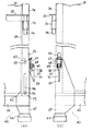
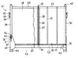
図1乃至図11において、21はコンテナで、その底部は鋼製の角パイプ部材を方形枠状に組み合わせて形成された底フレーム22と、底フレーム22から抜け落ちないようにしてフレーム上に着脱可能に設けられた底パネル23を備えたものとなっている。また底フレーム22の4隅角部には、鋼製の角パイプ部材でなる支柱24が、下部を各角部に設けられた隅板25にファスナ26によって固定されるようになっており、さらにコンテナ21の側面部分は、隣接する2本の支柱24に鋼製の角パイプ部材でなる横桟材27を渡すように設け、これらに木製の側面パネル28を固定することによって構成されている。
【0013】
そして、両端の支柱24の下部が対応する隅板25に枢支されており、これによって、支柱24と側面パネル28はコンテナ21の内方側に起倒可能となっている。なお、支柱24と側面パネル28の高さ寸法は、倒した際に底パネル23上に載るような大きさとなっている。また、側面パネル28の内面には上下方向に接触面積が小さくなるよう小幅に形成した、例えばフッ素樹脂やポリアミド樹脂等の低摩擦係数材料でなる数条の滑りガイド29が貼付されている。
【0014】
また、コンテナ21の前面部分と後面部分には、木製の前面パネル30と後面パネル31とが、内面側を側面パネル28の端面に当接させ、外面側の下部を底フレーム22の外面中央部に設けられたパネルガイド32および隅板25に当てるようにして間に形成された隙間に差し込み、さらに外面側の上部を支柱24の上部に固着されたガイドピン枠33に両端のガイドピン34を挿抜することで支柱24間に着脱可能に掛け渡されたL形鋼材のパネル押え35で押さえるようにして取り付けられている。そして、前面パネル30と後面パネル31とは、パネル押え35を着脱することにより着脱可能となっている。
【0015】
また、底フレーム22上に着脱可能に設けられた底パネル23は、鋼製の角パイプ部材を方形状に組み合わせた底板フレーム材36と、その内方側に交差するように組み合わせた鋼製の角パイプ部材の内側フレーム材37とを固定し、その上側全面に木製の底板38を張ることによって構成されている。そして底パネル23が底フレーム22上に載っている状態では、底板フレーム材36が底フレーム22上に載った状態になっており、さらに内側フレーム材37部分を下方側から昇降手段のリフト装置39を上昇、下降させることで底パネル23を昇降させることが可能となっている。
【0016】
なお、リフト装置39は、例えば図示しない蛍光灯等の生産ラインのラインヘッド近傍に形成された据付凹所Pに設けられており、図示しない駆動源により昇降部40を上下させて、先端部分に設けた昇降台41を昇降させるよう構成されている。そして、昇降台41を昇降させることによってコンテナ21の底パネル23の内側フレーム材37が押し上げ、引き下げられる。なおさらに、底板フレーム材36の下面にはずれ防止金具42が取り付けられており、昇降させた際に底パネル23が、位置ずれを起こさないようにして底フレーム22の適正位置に載るようになっている。
【0017】
また、底フレーム22の4隅角部に設けられた隅板25は、横断面形状がL字形状をしていて、その中間部が底フレーム22の隅角部の外側に固着されている。さらに隅板25の下部は下方向に延在するものとなっており、これにより底フレーム22の下方にコンテナ21を移送するための図示しないフォークリフトのフォークが差し込まれる差込スペース43が形成される。またさらに隅板25の下端には下方に向けて拡開する受皿44が固定されていて、この受皿44を支柱24上端に凸状曲面となるよう形成された受部45に被せるように載せることによって、コンテナ21を他のコンテナ21上に支持させることができるようになっている。
【0018】
一方、隅板25は、側面部分の支柱24と側面パネル28とを起倒可能に支持すると共に、支柱24を起立状態に固定するようL形に曲折した上部の片方側の側部に、長径方向を上下方向として所定寸法の長径を有する長孔46と、上端に形成された係合切欠47とを有しており、さらに上部の他方側の側部にファスナ26を備えている。そしてファスナ26は、隅板25の他方側の側部に固定された軸受部材48と、これに軸49により一端側が枢支され他端側を操作部50とした止め部材51と、止め部材51の中間部に形成された挿通孔52に遊嵌された止め環53とで構成されたものとなっている。
【0019】
これに対し、支柱24には、隅板25の長孔46に長径方向に移動すると共に回動するよう嵌め合わされる回動軸ピン54が下端に固着されており、これによって支柱24は長孔46内の任意の位置にある回動軸ピン54を中心に起倒する。また支柱24には、回動軸ピン54よりも上方の位置に、支柱24を起立させた時に隅板25の係合切欠47に係合させ、倒す時には外す係止ピン55が固着されている。さらに支柱24には、隅板25に設けられたファスナ26の止め環53を引掛けて起立状態にある支柱24を固定する止め金具56が、ファスナ26に対応した位置に取着されている。
【0020】
なお、57は、支柱24を底フレーム22上に起立させた際に、支柱24の下端と底フレーム22の上面との間の隙間を埋めるよう挿入されたスぺーサである。また、スペーサ57を設けることにより、折り畳み時に支柱24が底パネル23からはみ出さない長さに調整すると共に、組み立て時の有効支柱高さ、すなわち、コンテナ容積を拡大することができる。
【0021】
このように構成されたコンテナ21では、次のようにして組み立てを行う。先ず、支柱24と側面パネル28とを回動軸ピン54を中心に回動させ、係止ピン55を隅板25の係合切欠47に係合させると共にファスナ26の止め環53を止め金具56に引掛けてから止め部材51の操作部50を下方向に操作し、軸49を中心に止め部材51を回動させ、支柱24と側面パネル28とを起立状態に固定する。続いて前面パネル30と後面パネル31とを、それらの内面側を側面パネル28の端面に当接させ、外面側の下部を底フレーム22の外面中央部に設けられたパネルガイド32に当て、パネルガイド32と側面パネル28の端面との隙間に差し込み、さらに外面側の上部を、支柱24の上部にパネル押え35を取り付けることで押さえ、組み立てを完了する。
【0022】
このように組み立てられたコンテナ21への積載物である長尺のガラス管Gの積載は、ガラス管Gを底パネル23上に管軸方向を前後方向に揃えるようにして平面状に並べ、さらに並べられたガラス管Gの間に形成された凹み部分を埋め合わせるように次段のガラス管Gが管軸方向を合わせるようにして上に並べられ、これを繰り返し積み上げるように並べて多数のガラス管Gが積載される。
【0023】
また、ガラス管Gが積載されたコンテナ21は、例えば輸送手段として用いられる図示しないトラック等の車両に2段積みした状態で保管場所等に輸送される。さらに保管場所等では、支柱24の上端の受部45に他のコンテナ21の受皿44を載せるようにして、保管スペースや安全性等を考慮して所定段数積み上げられて保管がなされる。なお、輸送や保管等の際には、積載されたガラス管Gを保護防塵のために、ガラス管Gの上に保護板または防塵シート58が載せられる。
【0024】
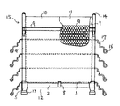
また、ガラス管Gの供給が行われる生産ライン等でのコンテナ21からの投入は、次のように行われる。すなわち、先ず、コンテナ21を保管場所等からガラス管投入場所である生産ラインのラインヘッド近傍に移動し、据付凹所Pに設置されたリフト装置39の昇降台41の上方に1つのコンテナ21を置く。その後、昇降部40によって昇降台41を上昇させ、ガラス管Gが積み上げられている底パネル23を、その内側フレーム材37部分を下方側から押し上げることで上昇させる。この底パネル23の押し上げに伴いコンテナ21内のガラス管Gは、側面パネル28の内面に貼付されている滑りガイド29により、欠けや破損等を生じることなく滑らかに押し上げられる。そして、積載されているガラス管Gの最上部のものが、例えば前面パネル30と後面パネル31の上端より若干高い所定高さになった時点で上昇を停止させる。
【0025】
続いて、据付凹所Pのラインヘッドとは逆側位置に設置されている図示しない移載手段により最上部のガラス管Gが、後面パネル31側の端部を管軸方向に押されて生産ラインのラインヘッドへ送り出される。送り出されたガラス管Gは、生産ライン上を1本ずつ整列された状態で流れ、蛍光灯等の所定製品の加工に供される。一方、最上部のガラス管Gが送り出されてしまうと、2段目に位置していたガラス管Gが、次の段階での最上部のガラス管Gとなり、再びこのガラス管Gが所定の高さに位置するようリフト装置39によって底パネル23の押し上げが行われる。そして、所定の高さに押し上げられたガラス管Gは、移載手段によって同様に生産ラインへ供給される。こうした過程を繰り返すことによりコンテナ21に積載されていたガラス管Gは、順次生産ラインに供給される。
【0026】
全てのガラス管が送り出されてしまうとリフト装置39の昇降台41が下降し、コンテナ21の底パネル23も底フレーム22上まで引き下げられる。そして空となったコンテナ21はラインヘッド近傍から外され、リフト装置39の上方にガラス管Gが積載されたコンテナ21が運び込まれる。これにより、再びリフト装置39と移載手段を使ってのガラス管Gの生産ラインへの供給が行われる。
【0027】
また、ラインヘッド近傍から外された空コンテナ21は、組み立て時とは逆に、次のようにして折り畳まれて保管、あるいは搬送される。すなわち、先ず前面側と後面側のパネル押え35を、両端のガイドピン34をガイドピン枠33から抜き取ることによって取り外す。これにより、前面パネル30と後面パネル31とを取り外す。続いて、ファスナ26の止め部材51を、操作部50を軸49を中心に上方向に引き起こすように回動させ、止め環53を止め金具56から外す。
【0028】
その後、図7(a)に示す第1の操作状態のように、直立している支柱24を実線矢印Aで示すように少し上方に引き上げながら係止ピン55を係合していた係合切欠47から外す。そして、図7(b)に示す第2の操作状態のように、隅板25の長孔46内で回動軸ピン54を回動させるようにして支柱24を実線矢印Bで示すように側面パネル28といっしょに回動させ、内方側に倒す。この時、長孔46の長径が所定寸法となっているので、先に倒れている一方の支柱24と側面パネル28の上に、他方の倒された支柱24と側面パネル28が重なり合う。
【0029】
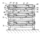
このように、両方の支柱24と側面パネル28を重ね合わせるようにした後、その上に前面パネル30や後面パネル31、さらにパネル押え35等を重ねるように載せる。このように折り畳むことで空コンテナ21は、隅板25の上端を超えない程度の高さのコンパクトな形態となる。そして、図8に示すように隅板25の上端に他の空コンテナ21の受皿44を載せるようにして所定段数積み上げを行い、空コンテナ21の保管場所に保管し、またガラス管Gを新たに積み込むために、積み込み場所に輸送手段のトラック等の車両に多段積みして回収輸送される。
【0030】
以上のように構成されているので、コンテナ21に積載されている長尺のガラス管Gの取り出しが、昇降手段のリフト装置39、移載手段を使って順時管軸方向に送り出すことにより行え、また昇降手段、移載手段の動きを生産ラインに連携させて制御することによって取り出し作業を簡単に自動化することもでき、人手によらず、またホイスト等を使用することなく、簡単かつ容易に行うことができ、さらにコンテナ上方にガラス管Gの取り出しを行うための大きなスペースを確保する必要がない。
【0031】
また、生産ラインの動きに合わせてコンテナ21からのガラス管Gの取り出しを行わせることにより、コンテナ21をラインホッパとして用いることができ、ラインヘッドにラインホッパを別途に設ける必要がなくなる。さらにまた、上記構成での取り出しでは、ガラス管Gは側面パネル28の内面に接触するようにして強制的に押し上げられるが、滑りガイド29が設けられていていることによって、滑らかに押し上げられることになり、ガラス管Gに破損等の生じる虞を抑制することができる。
【0032】
また、空となったコンテナ21については、ファスナ26等を操作することにより折り畳むことができ、空コンテナ21の保管や回送輸送等の際のスペース効率や搬送の効率を向上させることができる。また、空コンテナ21を隅板25の高さ以下に折り畳む作業等も、取り扱い易く手間が掛かるものではない。さらに、折り畳まれている空コンテナ21をガラス管Gが積載できるよう組み立てることも、支柱24と側面パネル28を回動させるようにして引き起こした後、係止ピン55を係合切欠47に係合させ、ファスナ26で固定するだけでよく、組立作業も簡単であり、がたつきなく確実に組み立てることができる。
【0033】
なお、上記のコンテナ21では前面パネル30と後面パネル31のみで積載するガラス管Gの前後を仕切るようにしているが、これに限るものではなく、上記実施形態と同一部分には同一符号を付した図9乃至図11に示す変形形態のように、積載するガラス管の長さに合わせ所定位置に中仕切パネルを設けるようにしてもよい。
【0034】
すなわち、コンテナ61は、鋼製の角パイプ部材を方形枠状に組み合わせて形成された底フレーム22と、底フレーム22から抜け落ちないようにしてフレーム上にリフト装置39によって昇降可能となるよう着脱可能に設けられた底パネル62を備え、側面部分は、隅板25にファスナ26により固定され立設された隣接する2本の支柱24に、鋼製の角パイプ部材でなる横桟材63を渡すように設け、これらに木製の側面パネル28を固定した構成のものとなっている。また、コンテナ61の前面部分と後面部分には、木製の前面パネル30と後面パネル31とが、支柱24間に着脱可能に掛け渡されたパネル押え35で押さえるようにして着脱可能に取り付けられている。そして、底パネル62と横桟材63には、前面パネル30から所定の距離離れた位置に仕切用孔64,65がそれぞれ形成されている。
【0035】
また、66は中仕切パネルで、これは離間して設けられた複数の縦桟材67を間に挟むよう両面に木製の仕切板68を固着するようにして構成されている。そして、両側の縦桟材67には、上端に先端部分が鉤形状となっていて横桟材63の仕切用孔64に係合する係合片部69が設けられており、中間部に設けられた縦桟材67には、下端に底パネル62の対応する仕切用孔65に係合する係合突起70が形成されている。
【0036】
このように構成されているので、中仕切パネル66を積載するガラス管の長さに合わせ、例えば上述の実施形態におけるガラス管Gの約半分の長さを有する短いガラス管を積載するに当たっては、略中央の仕切用孔64,65に対応する係合片部68の鉤形状先端部位と係合突起70を挿着し、前後方向に移動しないようにする。こうして組み立てられたコンテナ61の片方の内部空間に、ガラス管を底パネル62上に管軸方向を前後方向に揃えるようにして平面状に並べ、さらに並べられたガラス管の間に形成された凹み部分を埋め合わせるように次段のガラス管が管軸方向を合わせるようにして上に並べ、これを繰り返し積み上げるように並べて多数のガラス管が積載される。
【0037】
また、積載されたガラス管の取り出しは、上記の実施形態と同様に、先ずラインヘッドに設けられたリフト装置39の上方にコンテナ61を位置させ、ガラス管の両端を仕切っている前面パネル30、後面パネル31、さらに中仕切パネル66を取り外す。その後はリフト装置39で底パネル62を押し上げながら、所定高さに位置する最上部のガラス管を移載手段により押し出すようにして生産ラインに順次供給する。
【0038】
この結果、上記のような変形形態によれば、ガラス管の長さに対応して複数のコンテナを準備する必要がなく、中仕切パネル66のみで対応することができると共に、上記実施形態と同様の効果を得ることができる。なお、仕切用孔64,65を横桟材63、底パネル62に適宜の位置に形成し、複数の中仕切パネル66をガラス管の長さに応じて用いることにより、積載するガラス管の長さに応じて異種長さのガラス管を混載し、保管や輸送したりすることができる。
【0039】
また、中仕切パネル66の設定位置に合わせて底パネル62を分割すると共に、中仕切パネル66を底フレーム22に直接装着可能にすることで、分割された底パネル62を独立して昇降可能にでき、中仕切パネル66を取り外すことなく生産ラインのガラス管供給を行なうこともできる。
【0040】
【発明の効果】
以上の説明から明らかなように、本発明によればコンテナに積載された長尺の積載物の取り出しが、コンテナ上方に積載物の取り出しを行うための余分なスペースを確保することなく、手間を掛けずに容易に行えるようになり、また空コンテナを簡単な作業で折り畳むことができ、保管や回送輸送等の際のスペース効率や搬送効率が向上し、さらに組み立ても容易で手間が掛からず確実に行うことができ、取り扱い易い等の効果を有する。
【図面の簡単な説明】
【図1】本発明の一実施形態における一部断面で示す正面図である。
【図2】本発明の一実施形態を示す上面図である。
【図3】本発明の一実施形態における一部断面で示す側面図である。
【図4】本発明の一実施形態の要部を示す図で、図4(a)は正面図、図4(b)は側面図である。
【図5】本発明の一実施形態におけるガラス管を取り出す状況を前面パネルを外して示す正面図である。
【図6】積載時の積み重ね状態を示す正面図である。
【図7】本発明の一実施形態における支柱の起倒操作を説明するための図で、図7(a)は第1の操作状態を説明する図、図7(b)は第2の操作状態を説明する図である。
【図8】本発明の一実施形態における折り畳み時の積み重ね状態を示す正面図である。
【図9】本発明の一実施形態における変形形態の上面図である。
【図10】本発明の一実施形態における変形形態の一部断面で示す側面図である。
【図11】本発明の一実施形態における変形形態の中仕切パネルの正面図である。
【図12】第1の従来技術の一部断面で示す正面図である。
【図13】第1の従来技術の積み重ね状態における正面図である。
【図14】第2の従来技術の一部断面で示す正面図である。
【符号の説明】
22…底フレーム
23,62…底パネル
24…支柱
25…隅板
26…ファスナ
28…側面パネル
29…滑りガイド
30…前面パネル
31…後面パネル
35…パネル押え
39…リフト装置
44…受皿
45…受部
46…長孔
47…係合切欠
54…回動軸ピン
55…係止ピン
G…ガラス管[0001]
BACKGROUND OF THE INVENTION
The present invention relates to a container suitable for transporting and storing a long load such as a glass tube for a fluorescent lamp, and a method for using the same.
[0002]
[Prior art]
A conventional container for transporting and storing a glass tube for a fluorescent lamp will be described with reference to FIGS. 12 and 13 are diagrams according to the first prior art, FIG. 12 is a front view showing a partial cross section, and FIG. 13 is a front view in a stacked state. FIG. 14 is a front view showing a partial cross section of the second prior art.
[0003]
First, the first prior art will be described. 12 and 13, the
[0004]
In the
[0005]
In addition, the
[0006]
On the other hand, in order to facilitate the removal of the glass tube G from the
[0007]
However, in the case of the above-described configuration, even when a hoist is used to take out the glass tube G from the
[0008]
Also, when collecting, storing and forwarding
[0009]
[Problems to be solved by the invention]
The present invention has been made in view of the above situation, and the object is to be loaded in a container. Such as glass tube The removal of the long load is above the container Such as glass tube This makes it possible to easily carry out loading without taking up extra space for taking out the load, and to improve the space efficiency and transport efficiency when storing and forwarding empty containers. It is an object of the present invention to provide a container that can be improved and is easy to handle without troublesome work and the like, and a method for using the container.
[0010]
[Means for Solving the Problems]
The container of the present invention and the method of using the same are on a rectangular bottom frame. Detachable Providing a bottom panel and standing pillars at the four corners of the bottom frame The side panel is fixed to the support and the front panel and rear panel can be removed. Long and on the bottom panel Align the tube axis direction of the glass tube in the front-rear direction. Containers loaded, transported and stored side by side Then, on the inner surface side of the side panel, a sliding guide formed in a small width so as to reduce the contact area with the glass tube is attached, The bottom panel can be lifted and lowered by lifting means, and the bottom panel only The lifting means by the top Glass tube On the bottom panel by raising the Glass tube on top In order from the object to the long direction by transfer means Extrusion It can be moved and sent to a predetermined location,
In addition, corner plates are fixed to the four corners of the bottom frame. , The support is It is attached to the corner plate so that the lower part can be turned upside down, and is fixed to the corner plate by a fastener at the time of standing,
In addition, the bottom panel is provided on the rectangular bottom frame so that it can be raised and lowered by the lifting means, and the pillars with the side panels fixed by providing corner plates at the four corners of the bottom frame are erected so that they can be tilted. In addition, a front panel and a rear panel are detachably provided, and are long on the bottom panel. Align the tube axis direction of the glass tube in the front-rear direction. Loaded side by side, transported and stored, By attaching a narrow guide formed on the inner surface of the side panel, the contact area with the glass tube is reduced, Bottom panel only The lifting means by the top Glass tube On the bottom panel Glass tube on top In order from the object to the long direction by transfer means Extrusion A container that can be moved and sent to a predetermined location. Glass tube During storage and transportation, stack other containers by placing a tray provided at the lower end of the corner plate on the receiving part at the upper end of the upright column.Furthermore, when storing and transporting empty containers, install the front and rear panels. With the usage method characterized in that after the removal, the support column is tilted together with the side panel so that it is below the height of the corner plate, and other containers are stacked in multiple stages by placing a saucer on the upper end of the corner plate. is there.
[0011]
DETAILED DESCRIPTION OF THE INVENTION
Hereinafter, an embodiment of the present invention will be described with reference to FIGS. 1 is a front view showing a partial cross-section, FIG. 2 is a top view, FIG. 3 is a side view showing a partial cross-section, FIG. 4 is a diagram showing a main part, and FIG. FIG. 4 (b) is a side view, FIG. 5 is a front view showing a state in which the glass tube is taken out, with the front panel removed, and FIG. 6 is a front view showing a stacked state during loading. 7 is a diagram for explaining the operation of raising and lowering the support column, FIG. 7A is a diagram for explaining the first operation state, and FIG. 7B is a diagram for explaining the second operation state. 8 is a front view showing a stacked state at the time of folding, FIG. 9 is a top view of a modified embodiment, FIG. 10 is a side view showing a partial cross section of the modified embodiment, and FIG. 11 is a partition panel in the modified embodiment FIG.
[0012]
1 to 11,
[0013]
And the lower part of the support |
[0014]
Further, on the front part and the rear part of the
[0015]
Further, the
[0016]
The
[0017]
Further, the
[0018]
On the other hand, the
[0019]
On the other hand, the
[0020]
[0021]
The
[0022]
The long glass tube G, which is a load on the
[0023]
Further, the
[0024]
In addition, charging from the
[0025]
Subsequently, the uppermost glass tube G is pushed in the tube axis direction by the transfer means (not shown) installed at a position opposite to the line head of the installation recess P in the direction of the tube axis. Sent to the line head of the line. The fed glass tubes G flow in a state of being aligned one by one on the production line, and are used for processing a predetermined product such as a fluorescent lamp. On the other hand, when the uppermost glass tube G is sent out, the glass tube G located in the second stage becomes the uppermost glass tube G in the next stage, and this glass tube G is again set to a predetermined height. The
[0026]
When all the glass tubes are sent out, the
[0027]
Further, the
[0028]
After that, as in the first operation state shown in FIG. 7A, the engagement notch that engaged the
[0029]
Thus, after making both the support |
[0030]
Since it is configured as described above, the long glass tube G loaded in the
[0031]
Further, by causing the glass tube G to be taken out from the
[0032]
In addition, the
[0033]
In the
[0034]
That is, the
[0035]
[0036]
Since it is configured in this manner, according to the length of the glass tube on which the
[0037]
Further, in order to take out the loaded glass tube, as in the above embodiment, first, the
[0038]
As a result, according to the modified embodiment as described above, it is not necessary to prepare a plurality of containers corresponding to the length of the glass tube, and it is possible to cope with only the
[0039]
Further, the
[0040]
【The invention's effect】
As is clear from the above description, according to the present invention, it is possible to take out the long load loaded in the container without securing an extra space for removing the load above the container. It can be easily done without hanging, and empty containers can be folded by simple work, improving space efficiency and transport efficiency during storage and forwarding, etc., and assembly is easy and effortless. Can be easily performed, and has an effect such as easy handling.
[Brief description of the drawings]
FIG. 1 is a front view showing a partial cross section in an embodiment of the present invention.
FIG. 2 is a top view showing an embodiment of the present invention.
FIG. 3 is a side view showing a partial cross section in an embodiment of the present invention.
4A and 4B are diagrams showing a main part of an embodiment of the present invention, in which FIG. 4A is a front view and FIG. 4B is a side view.
FIG. 5 is a front view showing a state in which a glass tube is taken out according to an embodiment of the present invention with the front panel removed.
FIG. 6 is a front view showing a stacked state during loading.
FIGS. 7A and 7B are diagrams for explaining a column raising / lowering operation according to an embodiment of the present invention, FIG. 7A is a diagram illustrating a first operation state, and FIG. 7B is a second operation; It is a figure explaining a state.
FIG. 8 is a front view showing a stacked state when folded in an embodiment of the present invention.
FIG. 9 is a top view of a modification in one embodiment of the present invention.
FIG. 10 is a side view showing a partial cross section of a modified embodiment of the present invention.
FIG. 11 is a front view of a modified partition panel in an embodiment of the present invention.
FIG. 12 is a front view showing a partial cross section of the first prior art.
FIG. 13 is a front view of the first prior art in a stacked state.
FIG. 14 is a front view showing a partial cross section of the second prior art.
[Explanation of symbols]
22 ... Bottom frame
23, 62 ... Bottom panel
24 ... post
25 ... Corner plate
26. Fastener
28 ... Side panel
29 ... Slide guide
30 ... Front panel
31 ... Rear panel
35 ... Panel presser
39 ... Lifting device
44 ... saucer
45 ... receiving part
46 ... Long hole
47 ... engagement notch
54 ... Rotating shaft pin
55 ... Locking pin
G ... Glass tube
Claims (3)
Priority Applications (1)
| Application Number | Priority Date | Filing Date | Title |
|---|---|---|---|
| JP15246699A JP3679271B2 (en) | 1999-05-31 | 1999-05-31 | Container and its usage |
Applications Claiming Priority (1)
| Application Number | Priority Date | Filing Date | Title |
|---|---|---|---|
| JP15246699A JP3679271B2 (en) | 1999-05-31 | 1999-05-31 | Container and its usage |
Publications (2)
| Publication Number | Publication Date |
|---|---|
| JP2000335669A JP2000335669A (en) | 2000-12-05 |
| JP3679271B2 true JP3679271B2 (en) | 2005-08-03 |
Family
ID=15541137
Family Applications (1)
| Application Number | Title | Priority Date | Filing Date |
|---|---|---|---|
| JP15246699A Expired - Fee Related JP3679271B2 (en) | 1999-05-31 | 1999-05-31 | Container and its usage |
Country Status (1)
| Country | Link |
|---|---|
| JP (1) | JP3679271B2 (en) |
Cited By (1)
| Publication number | Priority date | Publication date | Assignee | Title |
|---|---|---|---|---|
| CN103318566A (en) * | 2013-03-14 | 2013-09-25 | 重庆万盛浮法玻璃有限公司 | Two-way opened glass packaging bracket |
Families Citing this family (2)
| Publication number | Priority date | Publication date | Assignee | Title |
|---|---|---|---|---|
| US20060124498A1 (en) * | 2004-12-14 | 2006-06-15 | Flanagan Patrick M | Collapsible crate |
| CN102530349A (en) * | 2012-02-14 | 2012-07-04 | 昆明昆船物流信息产业有限公司 | Universal foldable storage and transport frame basket for flat warehouses and stereoscopic warehouse and use method for frame basket |
-
1999
- 1999-05-31 JP JP15246699A patent/JP3679271B2/en not_active Expired - Fee Related
Cited By (2)
| Publication number | Priority date | Publication date | Assignee | Title |
|---|---|---|---|---|
| CN103318566A (en) * | 2013-03-14 | 2013-09-25 | 重庆万盛浮法玻璃有限公司 | Two-way opened glass packaging bracket |
| CN103318566B (en) * | 2013-03-14 | 2015-06-10 | 重庆万盛浮法玻璃有限公司 | Two-way opened glass packaging bracket |
Also Published As
| Publication number | Publication date |
|---|---|
| JP2000335669A (en) | 2000-12-05 |
Similar Documents
| Publication | Publication Date | Title |
|---|---|---|
| CA2465979C (en) | Foldable transport rack and methods of use thereof | |
| JP3723819B1 (en) | Pallet changer | |
| JP3679271B2 (en) | Container and its usage | |
| JPH09188327A (en) | Rack for transferring flat glass | |
| JP2012001300A (en) | Attachment for forklift and freight handling method using the same | |
| CN211767562U (en) | Storage frame is transported to packing box | |
| CN217497017U (en) | New energy automobile bonnet possesses greatly | |
| JPH0628487Y2 (en) | Cargo storage rack with transport mechanism | |
| JP2583745Y2 (en) | Tile transport trolley | |
| JPH10338352A (en) | Case loading-unloading installation | |
| JP4049262B2 (en) | Pallet mount | |
| CN113665648A (en) | Automatic hollow square brick handling device of stacking at interval | |
| JP2930485B2 (en) | Multi-stage picking shelf | |
| JP3039812U (en) | Goods storage shelves | |
| JPH0721587U (en) | Aircraft tire container | |
| JP3020342U (en) | Goods storage shelves | |
| JPH0859172A (en) | Transportation pallet suspending device | |
| JPH084421Y2 (en) | Parent-child pallet for transportation | |
| JP2946244B2 (en) | Pallet stacking device | |
| JPH0761601A (en) | Tire transfer device | |
| JP2022162373A (en) | Cargo push-off auxiliary device and cargo push-off method | |
| JPH09240812A (en) | Goods storing apparatus | |
| JPH0449076Y2 (en) | ||
| JPH0316824Y2 (en) | ||
| JPH0743042Y2 (en) | Platform for transporting shapes, etc. |
Legal Events
| Date | Code | Title | Description |
|---|---|---|---|
| A977 | Report on retrieval |
Free format text: JAPANESE INTERMEDIATE CODE: A971007 Effective date: 20050127 |
|
| A131 | Notification of reasons for refusal |
Free format text: JAPANESE INTERMEDIATE CODE: A131 Effective date: 20050208 |
|
| A521 | Written amendment |
Free format text: JAPANESE INTERMEDIATE CODE: A523 Effective date: 20050408 |
|
| RD04 | Notification of resignation of power of attorney |
Free format text: JAPANESE INTERMEDIATE CODE: A7424 Effective date: 20050418 |
|
| TRDD | Decision of grant or rejection written | ||
| A01 | Written decision to grant a patent or to grant a registration (utility model) |
Free format text: JAPANESE INTERMEDIATE CODE: A01 Effective date: 20050510 |
|
| A61 | First payment of annual fees (during grant procedure) |
Free format text: JAPANESE INTERMEDIATE CODE: A61 Effective date: 20050512 |
|
| R150 | Certificate of patent or registration of utility model |
Free format text: JAPANESE INTERMEDIATE CODE: R150 |
|
| FPAY | Renewal fee payment (event date is renewal date of database) |
Free format text: PAYMENT UNTIL: 20080520 Year of fee payment: 3 |
|
| S533 | Written request for registration of change of name |
Free format text: JAPANESE INTERMEDIATE CODE: R313533 |
|
| FPAY | Renewal fee payment (event date is renewal date of database) |
Free format text: PAYMENT UNTIL: 20080520 Year of fee payment: 3 |
|
| R350 | Written notification of registration of transfer |
Free format text: JAPANESE INTERMEDIATE CODE: R350 |
|
| FPAY | Renewal fee payment (event date is renewal date of database) |
Free format text: PAYMENT UNTIL: 20080520 Year of fee payment: 3 |
|
| FPAY | Renewal fee payment (event date is renewal date of database) |
Free format text: PAYMENT UNTIL: 20090520 Year of fee payment: 4 |
|
| FPAY | Renewal fee payment (event date is renewal date of database) |
Free format text: PAYMENT UNTIL: 20090520 Year of fee payment: 4 |
|
| FPAY | Renewal fee payment (event date is renewal date of database) |
Free format text: PAYMENT UNTIL: 20100520 Year of fee payment: 5 |
|
| FPAY | Renewal fee payment (event date is renewal date of database) |
Free format text: PAYMENT UNTIL: 20100520 Year of fee payment: 5 |
|
| FPAY | Renewal fee payment (event date is renewal date of database) |
Free format text: PAYMENT UNTIL: 20110520 Year of fee payment: 6 |
|
| FPAY | Renewal fee payment (event date is renewal date of database) |
Free format text: PAYMENT UNTIL: 20110520 Year of fee payment: 6 |
|
| FPAY | Renewal fee payment (event date is renewal date of database) |
Free format text: PAYMENT UNTIL: 20120520 Year of fee payment: 7 |
|
| FPAY | Renewal fee payment (event date is renewal date of database) |
Free format text: PAYMENT UNTIL: 20130520 Year of fee payment: 8 |
|
| FPAY | Renewal fee payment (event date is renewal date of database) |
Free format text: PAYMENT UNTIL: 20140520 Year of fee payment: 9 |
|
| S531 | Written request for registration of change of domicile |
Free format text: JAPANESE INTERMEDIATE CODE: R313531 |
|
| FPAY | Renewal fee payment (event date is renewal date of database) |
Free format text: PAYMENT UNTIL: 20140520 Year of fee payment: 9 |
|
| R350 | Written notification of registration of transfer |
Free format text: JAPANESE INTERMEDIATE CODE: R350 |
|
| LAPS | Cancellation because of no payment of annual fees |