JP3677832B2 - Magnetic separator for activated sludge with magnetic powder addition - Google Patents
Magnetic separator for activated sludge with magnetic powder addition Download PDFInfo
- Publication number
- JP3677832B2 JP3677832B2 JP25502595A JP25502595A JP3677832B2 JP 3677832 B2 JP3677832 B2 JP 3677832B2 JP 25502595 A JP25502595 A JP 25502595A JP 25502595 A JP25502595 A JP 25502595A JP 3677832 B2 JP3677832 B2 JP 3677832B2
- Authority
- JP
- Japan
- Prior art keywords
- activated sludge
- flow path
- donut
- discharging means
- plate
- Prior art date
- Legal status (The legal status is an assumption and is not a legal conclusion. Google has not performed a legal analysis and makes no representation as to the accuracy of the status listed.)
- Expired - Fee Related
Links
- 239000010802 sludge Substances 0.000 title claims description 98
- 239000006148 magnetic separator Substances 0.000 title claims description 12
- 239000006247 magnetic powder Substances 0.000 title claims description 11
- XLYOFNOQVPJJNP-UHFFFAOYSA-N water Substances O XLYOFNOQVPJJNP-UHFFFAOYSA-N 0.000 claims description 35
- 239000007788 liquid Substances 0.000 claims description 25
- 238000007599 discharging Methods 0.000 claims description 23
- 238000007790 scraping Methods 0.000 claims description 21
- 238000011144 upstream manufacturing Methods 0.000 claims description 12
- 230000002265 prevention Effects 0.000 claims description 8
- 230000002093 peripheral effect Effects 0.000 claims description 6
- 238000000034 method Methods 0.000 description 9
- 239000010865 sewage Substances 0.000 description 9
- 239000006228 supernatant Substances 0.000 description 6
- 238000004062 sedimentation Methods 0.000 description 5
- 238000010586 diagram Methods 0.000 description 4
- 238000005192 partition Methods 0.000 description 3
- 238000011084 recovery Methods 0.000 description 3
- 238000005273 aeration Methods 0.000 description 2
- 238000001556 precipitation Methods 0.000 description 2
- 238000000926 separation method Methods 0.000 description 2
- ZAMOUSCENKQFHK-UHFFFAOYSA-N Chlorine atom Chemical compound [Cl] ZAMOUSCENKQFHK-UHFFFAOYSA-N 0.000 description 1
- 230000004931 aggregating effect Effects 0.000 description 1
- 229910052801 chlorine Inorganic materials 0.000 description 1
- 239000000460 chlorine Substances 0.000 description 1
- 230000007423 decrease Effects 0.000 description 1
- 230000000694 effects Effects 0.000 description 1
- 230000005484 gravity Effects 0.000 description 1
- 239000008235 industrial water Substances 0.000 description 1
- 238000007885 magnetic separation Methods 0.000 description 1
- 239000002244 precipitate Substances 0.000 description 1
- 230000001737 promoting effect Effects 0.000 description 1
- 239000004576 sand Substances 0.000 description 1
- 239000000126 substance Substances 0.000 description 1
Images

Classifications
-
- B—PERFORMING OPERATIONS; TRANSPORTING
- B03—SEPARATION OF SOLID MATERIALS USING LIQUIDS OR USING PNEUMATIC TABLES OR JIGS; MAGNETIC OR ELECTROSTATIC SEPARATION OF SOLID MATERIALS FROM SOLID MATERIALS OR FLUIDS; SEPARATION BY HIGH-VOLTAGE ELECTRIC FIELDS
- B03C—MAGNETIC OR ELECTROSTATIC SEPARATION OF SOLID MATERIALS FROM SOLID MATERIALS OR FLUIDS; SEPARATION BY HIGH-VOLTAGE ELECTRIC FIELDS
- B03C1/00—Magnetic separation
- B03C1/02—Magnetic separation acting directly on the substance being separated
- B03C1/025—High gradient magnetic separators
- B03C1/031—Component parts; Auxiliary operations
- B03C1/033—Component parts; Auxiliary operations characterised by the magnetic circuit
- B03C1/0332—Component parts; Auxiliary operations characterised by the magnetic circuit using permanent magnets
-
- B—PERFORMING OPERATIONS; TRANSPORTING
- B03—SEPARATION OF SOLID MATERIALS USING LIQUIDS OR USING PNEUMATIC TABLES OR JIGS; MAGNETIC OR ELECTROSTATIC SEPARATION OF SOLID MATERIALS FROM SOLID MATERIALS OR FLUIDS; SEPARATION BY HIGH-VOLTAGE ELECTRIC FIELDS
- B03C—MAGNETIC OR ELECTROSTATIC SEPARATION OF SOLID MATERIALS FROM SOLID MATERIALS OR FLUIDS; SEPARATION BY HIGH-VOLTAGE ELECTRIC FIELDS
- B03C1/00—Magnetic separation
- B03C1/02—Magnetic separation acting directly on the substance being separated
- B03C1/10—Magnetic separation acting directly on the substance being separated with cylindrical material carriers
- B03C1/12—Magnetic separation acting directly on the substance being separated with cylindrical material carriers with magnets moving during operation; with movable pole pieces
-
- B—PERFORMING OPERATIONS; TRANSPORTING
- B03—SEPARATION OF SOLID MATERIALS USING LIQUIDS OR USING PNEUMATIC TABLES OR JIGS; MAGNETIC OR ELECTROSTATIC SEPARATION OF SOLID MATERIALS FROM SOLID MATERIALS OR FLUIDS; SEPARATION BY HIGH-VOLTAGE ELECTRIC FIELDS
- B03C—MAGNETIC OR ELECTROSTATIC SEPARATION OF SOLID MATERIALS FROM SOLID MATERIALS OR FLUIDS; SEPARATION BY HIGH-VOLTAGE ELECTRIC FIELDS
- B03C1/00—Magnetic separation
- B03C1/02—Magnetic separation acting directly on the substance being separated
- B03C1/28—Magnetic plugs and dipsticks
- B03C1/286—Magnetic plugs and dipsticks disposed at the inner circumference of a recipient, e.g. magnetic drain bolt
-
- B—PERFORMING OPERATIONS; TRANSPORTING
- B03—SEPARATION OF SOLID MATERIALS USING LIQUIDS OR USING PNEUMATIC TABLES OR JIGS; MAGNETIC OR ELECTROSTATIC SEPARATION OF SOLID MATERIALS FROM SOLID MATERIALS OR FLUIDS; SEPARATION BY HIGH-VOLTAGE ELECTRIC FIELDS
- B03C—MAGNETIC OR ELECTROSTATIC SEPARATION OF SOLID MATERIALS FROM SOLID MATERIALS OR FLUIDS; SEPARATION BY HIGH-VOLTAGE ELECTRIC FIELDS
- B03C1/00—Magnetic separation
- B03C1/02—Magnetic separation acting directly on the substance being separated
- B03C1/10—Magnetic separation acting directly on the substance being separated with cylindrical material carriers
- B03C1/14—Magnetic separation acting directly on the substance being separated with cylindrical material carriers with non-movable magnets
- B03C1/145—Magnetic separation acting directly on the substance being separated with cylindrical material carriers with non-movable magnets with rotating annular or disc-shaped material carriers
-
- B—PERFORMING OPERATIONS; TRANSPORTING
- B03—SEPARATION OF SOLID MATERIALS USING LIQUIDS OR USING PNEUMATIC TABLES OR JIGS; MAGNETIC OR ELECTROSTATIC SEPARATION OF SOLID MATERIALS FROM SOLID MATERIALS OR FLUIDS; SEPARATION BY HIGH-VOLTAGE ELECTRIC FIELDS
- B03C—MAGNETIC OR ELECTROSTATIC SEPARATION OF SOLID MATERIALS FROM SOLID MATERIALS OR FLUIDS; SEPARATION BY HIGH-VOLTAGE ELECTRIC FIELDS
- B03C2201/00—Details of magnetic or electrostatic separation
- B03C2201/18—Magnetic separation whereby the particles are suspended in a liquid
-
- Y—GENERAL TAGGING OF NEW TECHNOLOGICAL DEVELOPMENTS; GENERAL TAGGING OF CROSS-SECTIONAL TECHNOLOGIES SPANNING OVER SEVERAL SECTIONS OF THE IPC; TECHNICAL SUBJECTS COVERED BY FORMER USPC CROSS-REFERENCE ART COLLECTIONS [XRACs] AND DIGESTS
- Y02—TECHNOLOGIES OR APPLICATIONS FOR MITIGATION OR ADAPTATION AGAINST CLIMATE CHANGE
- Y02W—CLIMATE CHANGE MITIGATION TECHNOLOGIES RELATED TO WASTEWATER TREATMENT OR WASTE MANAGEMENT
- Y02W10/00—Technologies for wastewater treatment
- Y02W10/10—Biological treatment of water, waste water, or sewage
Landscapes
- Activated Sludge Processes (AREA)
Description
【0001】
【発明の属する技術分野】
本発明は、磁力を利用して活性汚泥液から活性汚泥を分離回収するための磁性粉添加活性汚泥の磁気分離機に係り、特に活性汚泥液中で連続的に活性汚泥の分離回収を行う磁性粉添加活性汚泥の磁気分離機に関するものである。
【0002】
【従来の技術】
下水処理のプロセスとしては、図4に示すように、各所から集められた下水は下水処理場29に導かれると、先ず沈砂池30に入り、大きな土砂が除去され、次いでスクリーン(図示せず)に送られて下水中の遺物が除去され、ポンプ(図示せず)により第1沈澱地31へ送られる。ここで細かい沈澱物が除去されて、上澄水は深さ3〜5mの散気式曝気槽32へ送られる。
【0003】
曝気槽32では、下水処理量の25〜35%程度(容積比)の活性汚泥を混和した下水に、処理下水量の3〜7倍の空気を槽の上部に設けた散気板34から噴出させると、下水は活性汚泥で分解される。
【0004】
この状態になった曝気液35を第2沈澱地33に流入させて活性汚泥を沈澱させると、その上澄液は非常にきれいなものとなるから、更に塩素を加えて殺菌し、最後にphを調節すれば無害なものとなる。これを河川または海へ排出するか、場合によっては工業用水として回収再使用するのである。
【0005】
上記方式は、水中の浮游物質を重力の作用によって自然に沈降させることから普通沈澱法(自然沈澱法)と呼ばれる。特に自然沈澱法の第2沈澱地33においては、自然沈降の代わりに、特開昭48−42570号公報に開示されるように、活性汚泥液中に磁性粉を添加混入し、これを磁界に通過させることにより、活性汚泥を凝集させて、活性汚泥液の固液分離を促進させる方法が提案されている。
【0006】
具体的には、特開昭63−59759号公報に開示されているように、磁石を持つ回転体の一部を活性汚泥液が流れる流路に沈めて、直接または間接に活性汚泥を磁着し、強制的に活性汚泥と処理水を分離した後、この回転体を垂直方向に回転させて、回転体に磁着した活性汚泥を液面上に引き上げ、この活性汚泥を連続的に掻き取る方法が提案されている。
【0007】
【発明が解決しようとする課題】
しかしながら上記方式であると、活性汚泥を液面上に引き上げるとき、磁石に磁着した活性汚泥は浮力を失うために、その一部は液面下にこぼれ落ちてしまい、回収効率が低下してしまうという問題が生じた。
【0008】
そこで本発明の目的は、上記課題を解決するために、活性汚泥液中で活性汚泥と処理水の分離及び活性汚泥の回収を連続的に行い、磁石に磁着された活性汚泥を液中で回収することができる磁性粉添加活性汚泥の磁気分離機を提供するものである。
【0009】
【課題を解決するための手段】
上記目的を達成するために請求項1の発明は、横断面が略円形を呈する処理槽と、該処理槽内の軸芯部に起立して回転自在に設けられ、その外周部にドーナツ状の流路を形成するための回転ドラムと、該回転ドラムの下部に径方向外方に延出されて上記ドーナツ状の流路の底部を区画する磁石板と、上記ドーナツ状の流路に設けられ、該流路の上流側と下流側とに仕切ると共に下端部が上記磁石板の表面に接して該磁石板に付着する活性汚泥を掻き取るための掻取板と、上記ドーナツ状の流路の上流側に被処理水である活性汚泥液を導入するための活性汚泥液導入手段と、上記ドーナツ状の流路の最下流側に設けられた上記掻取板により掻き取られた活性汚泥を系外に排出するための活性汚泥排出手段と、該活性汚泥排出手段より上流側に設けられた処理水排出手段を備え、上記回転ドラムを回転駆動させて磁石板を回転させ、上記ドーナツ状の流路下に沈降する活性汚泥を上記活性汚泥排出手段により掻き取り排出するように構成した磁性粉添加活性汚泥の磁気分離機である。
【0010】
請求項2の発明は、上記処理水排出手段と上記活性汚泥排出手段との間に、活性汚泥の逆流防止板が設けられた請求項1記載の磁性粉添加活性汚泥の磁気分離機である。
【0011】
上記構成によれば、活性汚泥液導入手段を経て流入した、磁性粉の混入された活性汚泥液は、回転ドラムによって形成されたドーナツ状の流路を回転ドラムに巻き付くように流れて行き、その間に活性汚泥は磁石板に磁着され、上澄液は処理水排出手段より排出される。また、磁石板に磁着した活性汚泥は、掻取板で掻き取られて、活性汚泥排出手段より排出される。一方、活性汚泥が掻き取られて再生された磁石板は、再び上流端から回転する。
【0012】
【発明の実施の形態】
次に、本発明の実施の形態を添付図面に基づいて詳述する。
【0013】
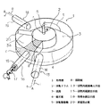
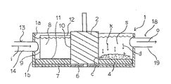
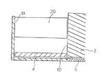
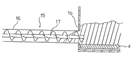
図1は本発明の磁気分離機の概略斜視図を示したもので、図2は図1の回転軸を含むA−A線断面図である。更に、図3は図1に示す逆流防止板の詳細を示す図である。図4は図1に示す汚泥排出手段の詳細を示す図である。
【0014】
図1、図2に示すように、処理槽1はその横断面が略円形を呈する有底筒体状に形成され、その処理槽1内の軸芯部ないし中央部には所定の断面積を有する回転ドラム2が起立して回転自在に設けられている。この回転ドラム2はその頂部に回転駆動軸5が連設されていると共に、下部には軸受6が設けられて、処理槽1の底板7に回転自在に支持されている。この回転ドラム2の外周部には処理槽1の内周壁1aによって区画形成されたドーナツ状の流路3が形成されている。
【0015】
また、回転ドラム2の下部には径方向外方に拡径されて延出された磁石板4が設けられ、この磁石板4は上記ドーナツ状の流路3の底部を区画するように構成されている。
【0016】
また、この磁石板4は回転ドラム2に取り付けられると共に処理槽1の底板7より所定の間隙を隔てて取り付けられており、上記ドーナツ状の流路3の底部を一方向に回転するように構成されている。上記ドーナツ状の流路3には上流側と下流側とに仕切るとともに磁石板4に付着する活性汚泥cを掻き取るための掻取板8が設けられている。この掻取板8はその一端部9が処理槽1の内周壁1aに固定され、他端10が回転ドラム2の外周部に摺接され、かつ下端部11が磁石板4の表面に摺接するように取り付けられている。また、掻取板8の上端部12はドーナツ状の流路3に形成される処理水位より所定の高さ位置に形成され、ドーナツ状の流路3の上流側と下流側とを的確に仕切るように構成されている。
【0017】
処理槽1にはドーナツ状の流路3の最上流側となる掻取板8の一側面に近接させて被処理水である活性汚泥液sを導入するための活性汚泥導入手段13が設けられている。この活性汚泥導入手段13は図示例にあっては処理槽1に挿通された導入管14によって構成されている。
【0018】
ドーナツ状の流路3の最下流側には掻取板8によって掻き取られた活性汚泥を系外すなわち処理槽1外に排出するための活性汚泥排出手段15が設けられている。この活性汚泥排出手段15は図1、図4に示すようにドーナツ状の流路3の最下流側を形成する掻取板8に近接されて設けられ、処理槽1の側壁1bにこれを貫通して取り付けられた排出管16とこの排出管16の内部に設けられたスクリューコンベア17とによって構成されている。このスクリューコンベア17は図示されないが、駆動源が設けられており、このスクリューコンベア17が回転されることによって掻き取られた活性汚泥cが処理槽1外に排出されるように構成されている。
【0019】
処理槽1には活性汚泥排出手段15より上流側に位置されて活性汚泥cが取り除かれた上澄の処理水を系外に排出する処理水排出手段18が設けられている。この処理水排出手段18は図1、図2に示すように処理槽1の側壁1bに取り付けられた排水管19によって構成されている。特に、この処理水排出手段18は上記活性汚泥排出手段15より所定の距離を隔ててその上流側に設けられ、処理水排出手段18と活性汚泥排出手段15との間には掻取板8によって磁石板4より掻き取られた活性汚泥cを系外に排出すべく沈降滞留させておくゾーン3aを形成する。
【0020】
また、処理水排出手段18の下流側に位置されるドーナツ状の流路3には上記ゾーン3aから掻き取られた活性汚泥cが逆流することを防止するための逆流防止板20が設けられている。この逆流防止板20はその一端が処理槽1の内壁に固定支持され、他端が回転ドラム2に摺接して回転ドラム2の回転を許容し、上端が処理水の水位より所定の高さ露出し、かつ下端が処理水の上部から半分までの深さに延出されて構成されている。
【0021】
次に実施の形態の作用について説明する。
【0022】
図1、図2に示すように、処理槽1内に活性汚泥導入手段13を構成する導入管14を介して被処理水としての磁性粉が混入された活性汚泥液sを導入する。処理槽1内に被処理水としての磁性粉が混入された活性汚泥液sは回転ドラム2と処理槽1の内周壁に区画されたドーナツ状の流路3に沿って流れ、ドーナツ状の流路3の上流側から下流側に(矢印t方向に)流れる間に、活性汚泥液s中の活性汚泥cは凝集し、その凝集体kは流路3を進むに従って磁石板4に、その磁力によって引き付けられながら矢印d方向に沈降することになる。活性汚泥cが沈降除去された上澄水としての処理水は下流側となる処理水排出手段18を構成する排水管19より系外に取り出されることになる。
【0023】
沈降した凝集体kは磁石板4に磁着され、磁石板4は回転駆動軸5が図示されない駆動源により回転駆動されると、回転ドラム2が回転されることにより、活性汚泥液sの流れと同一方向の矢印r方向に回転されることにより、磁石板4上に磁着された活性汚泥cが磁石板4に搬送されて下流側に移動する。
【0024】
その後、磁石板4の回転駆動により、磁石板4上に磁着された活性汚泥cはドーナツ状の流路3最下流側に位置される掻取板8に当たり、その掻取板8によって掻き取られ、活性汚泥排出手段15によって系外に排出されることになる。
【0025】
掻取板8によって回転駆動する磁石板4より掻き取られた活性汚泥cは掻取板8近傍のゾーン3aの処理水中に掻き寄せられることになり、掻き寄せられた活性汚泥cは活性汚泥排出手段15を構成するスクリューコンベア17により強制的に排出管16を通して系外に排出されることになる。
【0026】
特に、本実施の形態にあってはドーナツ状の流路3の最下流側を形成する掻取板8より所定の距離を隔てて処理水排出手段18を設けると共にこの処理水排出手段18と掻取板8との間に逆流防止板20が設けられていることから、掻き取られた活性汚泥cが上記処理水排出手段18側に逆流し、系外に流出することを未然に防止することができ、上澄液のみが処理水排出手段18から系外に取り出せる。
【0027】
尚、本実施の形態にあっては処理槽1は上部が開放された有底筒体状の槽体によって構成されているが、上部にこれを覆って閉じるための蓋体を設けても良いことは勿論である。
【0028】
また、処理槽1を上下方向に多段に重ね合わせて、例えば上部の処理槽の排水管19と下部の処理槽の導入管14を繋いだ多段式磁気分離機を形成すると、活性汚泥cと処理水への分離効率が格段に向上する。
【0029】
特に、活性汚泥cを活性汚泥液s中で回収することにより、活性汚泥cを液面上に引き上げることがないので、従来のように磁石に磁着した活性汚泥cをこぼして回収効率を低下させてしまうという問題が解消される。
【0030】
【発明の効果】
以上要するに本発明によれば、濃縮された磁性汚泥を液面上に引き上げないで分離することから、磁石に磁着した活性汚泥を完全に回収できるので、分解効率が高い磁性粉添加活性汚泥の磁気分離機を提供できる。このため、比較的下水処理設備の占有面積を確保できない場所にも下水処理システムを普及させることができるようになる。
【図面の簡単な説明】
【図1】本発明の実施の形態を示した概略斜視図である。
【図2】図1の回転軸を含むA−A線断面図である。
【図3】図1に示す逆流防止板の詳細を示す図である。
【図4】図1に示す活性汚泥排出手段の詳細を示す図である。
【図5】従来の下水処理のプロセスを示した概略図である。
【符号の説明】
1 処理槽
2 回転ドラム
3 流路
4 磁石板
5 回転駆動軸
8 掻取板
13 活性汚泥液導入手段
15 活性汚泥排出手段
18 処理水排出手段
20 逆流防止板[0001]
BACKGROUND OF THE INVENTION
TECHNICAL FIELD The present invention relates to a magnetic powder addition activated sludge magnetic separator for separating and recovering activated sludge from activated sludge using magnetic force, and in particular, magnetic separation and recovery of activated sludge continuously in activated sludge liquid. The present invention relates to a magnetic separator for powdered activated sludge.
[0002]
[Prior art]
As shown in FIG. 4, when the sewage collected from various places is led to the
[0003]
In the
[0004]
When the
[0005]
The above method is called a normal precipitation method (natural precipitation method) because it causes the floating substance in water to settle naturally by the action of gravity. In particular, in the second sedimentation site 33 of the natural sedimentation method, instead of natural sedimentation, magnetic powder is added and mixed in the activated sludge liquid as disclosed in JP-A-48-42570, and this is used as a magnetic field. There has been proposed a method of aggregating activated sludge by passing it and promoting solid-liquid separation of the activated sludge liquid.
[0006]
Specifically, as disclosed in JP-A-63-59759, a part of a rotating body having a magnet is submerged in a flow path through which activated sludge liquid flows, and activated sludge is magnetized directly or indirectly. After forcibly separating the activated sludge and the treated water, the rotating body is rotated in the vertical direction, the activated sludge magnetically attached to the rotating body is pulled up on the liquid surface, and the activated sludge is scraped continuously. A method has been proposed.
[0007]
[Problems to be solved by the invention]
However, in the case of the above method, when the activated sludge is pulled up on the liquid surface, the activated sludge magnetically attached to the magnet loses buoyancy, so that a part of the sludge spills below the liquid surface and the recovery efficiency decreases. The problem that occurred.
[0008]
Therefore, in order to solve the above problems, the object of the present invention is to continuously separate activated sludge and treated water and collect activated sludge in the activated sludge liquid, and the activated sludge magnetically attached to the magnet in the liquid. A magnetic separator for adding activated magnetic sludge with magnetic powder that can be recovered is provided.
[0009]
[Means for Solving the Problems]
In order to achieve the above object, the invention according to
[0010]
The invention according to
[0011]
According to the above configuration, the activated sludge liquid mixed in with the magnetic powder flowing in through the activated sludge liquid introducing means flows so as to wind the donut-shaped flow path formed by the rotating drum around the rotating drum, In the meantime, the activated sludge is magnetized on the magnet plate, and the supernatant is discharged from the treated water discharge means. The activated sludge magnetically attached to the magnet plate is scraped off by the scraping plate and discharged from the activated sludge discharging means. On the other hand, the magnet plate regenerated by scraping the activated sludge rotates again from the upstream end.
[0012]
DETAILED DESCRIPTION OF THE INVENTION
Next, embodiments of the present invention will be described in detail with reference to the accompanying drawings.
[0013]
FIG. 1 is a schematic perspective view of a magnetic separator according to the present invention, and FIG. 2 is a cross-sectional view taken along line AA including the rotating shaft of FIG. FIG. 3 is a diagram showing details of the backflow prevention plate shown in FIG. FIG. 4 is a diagram showing details of the sludge discharging means shown in FIG.
[0014]
As shown in FIGS. 1 and 2, the
[0015]
In addition, a
[0016]
The
[0017]
The
[0018]
An activated sludge discharging means 15 for discharging activated sludge scraped off by the
[0019]
The
[0020]
The donut-shaped
[0021]
Next, the operation of the embodiment will be described.
[0022]
As shown in FIGS. 1 and 2, an activated sludge liquid s mixed with magnetic powder as water to be treated is introduced into a
[0023]
The settled aggregate k is magnetically attached to the
[0024]
After that, the activated sludge c magnetized on the
[0025]
The activated sludge c scraped from the
[0026]
In particular, in the present embodiment, the treated water discharge means 18 is provided at a predetermined distance from the
[0027]
In the present embodiment, the
[0028]
Further, when the multi-stage magnetic separator is formed by stacking the
[0029]
In particular, by collecting activated sludge c in the activated sludge liquid s, the activated sludge c is not lifted onto the liquid surface, so that the activated sludge c magnetically attached to the magnet as in the past is spilled to reduce the recovery efficiency. The problem of letting it go away is solved.
[0030]
【The invention's effect】
In short, according to the present invention, since the concentrated magnetic sludge is separated without being pulled up on the liquid surface, the activated sludge magnetically attached to the magnet can be completely recovered. A magnetic separator can be provided. For this reason, it becomes possible to spread the sewage treatment system even in a place where the occupation area of the sewage treatment facility cannot be secured.
[Brief description of the drawings]
FIG. 1 is a schematic perspective view showing an embodiment of the present invention.
2 is a cross-sectional view taken along line AA including the rotation shaft of FIG.
FIG. 3 is a diagram showing details of the backflow prevention plate shown in FIG. 1;
FIG. 4 is a diagram showing details of the activated sludge discharging means shown in FIG.
FIG. 5 is a schematic view showing a conventional sewage treatment process.
[Explanation of symbols]
DESCRIPTION OF
Claims (2)
Priority Applications (1)
| Application Number | Priority Date | Filing Date | Title |
|---|---|---|---|
| JP25502595A JP3677832B2 (en) | 1995-10-02 | 1995-10-02 | Magnetic separator for activated sludge with magnetic powder addition |
Applications Claiming Priority (1)
| Application Number | Priority Date | Filing Date | Title |
|---|---|---|---|
| JP25502595A JP3677832B2 (en) | 1995-10-02 | 1995-10-02 | Magnetic separator for activated sludge with magnetic powder addition |
Publications (2)
| Publication Number | Publication Date |
|---|---|
| JPH0994593A JPH0994593A (en) | 1997-04-08 |
| JP3677832B2 true JP3677832B2 (en) | 2005-08-03 |
Family
ID=17273146
Family Applications (1)
| Application Number | Title | Priority Date | Filing Date |
|---|---|---|---|
| JP25502595A Expired - Fee Related JP3677832B2 (en) | 1995-10-02 | 1995-10-02 | Magnetic separator for activated sludge with magnetic powder addition |
Country Status (1)
| Country | Link |
|---|---|
| JP (1) | JP3677832B2 (en) |
Families Citing this family (3)
| Publication number | Priority date | Publication date | Assignee | Title |
|---|---|---|---|---|
| CN109107278A (en) * | 2018-09-18 | 2019-01-01 | 安徽包钢稀土永磁合金制造有限责任公司 | A kind of NdFeB rear-earth alloy Environmental-protection dust removal device |
| CN110002659A (en) * | 2019-04-17 | 2019-07-12 | 天津绿诺环保科技有限公司 | A kind of sewage separating and treating apparatus using magnetic powder |
| CN111841885B (en) * | 2020-05-29 | 2022-08-09 | 华电电力科学研究院有限公司 | Continuous separation device for magnetic particles in slurry |
-
1995
- 1995-10-02 JP JP25502595A patent/JP3677832B2/en not_active Expired - Fee Related
Also Published As
| Publication number | Publication date |
|---|---|
| JPH0994593A (en) | 1997-04-08 |
Similar Documents
| Publication | Publication Date | Title |
|---|---|---|
| US4039447A (en) | Waste water treatment method and apparatus | |
| US20080073284A1 (en) | Device and method for utilizing magnetic seeding and separation in a water treatment system | |
| JP5172294B2 (en) | Muddy water purification device | |
| US20080073281A1 (en) | Method and Apparatus for Batch Treating Water Utilizing Magnetic Separation | |
| US20160221845A1 (en) | Magnetic ballast clarification designs and applications | |
| GB2448015A (en) | Magnetic separation filtering and cleaning apparatus | |
| JP2019126760A (en) | Sewage treatment system and stirring device | |
| JP2010527787A (en) | Hydrocyclone floating separator and water pollution control system including the same | |
| CN209307062U (en) | A kind of chemical engineering sewage processing unit | |
| JP2005111424A (en) | Method and apparatus for removing object to be removed from fluid and sludge separation and recovery device | |
| KR101307288B1 (en) | Device for Reducing Particulate Pollutants in Early Rainfall Runoff | |
| CN206408022U (en) | A kind of tap water purifying system | |
| JP3677832B2 (en) | Magnetic separator for activated sludge with magnetic powder addition | |
| CN212476431U (en) | Oil field hypersalinity sewage treatment plant | |
| JP2004113940A (en) | Moving bed type filtration apparatus and operation method thereof | |
| CN208561944U (en) | A kind of earth's surface water pre-treatment means and graphene filter | |
| CN106492520A (en) | A kind of girt-water separation device and method | |
| WO1990011813A1 (en) | Liquid processing apparatus, its continuous liquid processing apparatus and its continuous liquid processing method | |
| KR100986634B1 (en) | Pretreatment equipment of sludge or sewage | |
| CN216549772U (en) | Sewage treatment tank convenient to maintain | |
| CN110066036A (en) | Dock ship oily water receiving and processing device and method | |
| JP3387696B2 (en) | Suspension clarification equipment | |
| KR200179035Y1 (en) | Disposal device of waste water with oil | |
| JP3759811B2 (en) | Sewage / septic tank sludge treatment equipment equipped with the same sand removal device from human waste / septic tank sludge | |
| JP2003251114A (en) | Solid-liquid separation device |
Legal Events
| Date | Code | Title | Description |
|---|---|---|---|
| A977 | Report on retrieval |
Free format text: JAPANESE INTERMEDIATE CODE: A971007 Effective date: 20040714 |
|
| TRDD | Decision of grant or rejection written | ||
| A01 | Written decision to grant a patent or to grant a registration (utility model) |
Free format text: JAPANESE INTERMEDIATE CODE: A01 Effective date: 20050419 |
|
| A61 | First payment of annual fees (during grant procedure) |
Free format text: JAPANESE INTERMEDIATE CODE: A61 Effective date: 20050502 |
|
| FPAY | Renewal fee payment (event date is renewal date of database) |
Free format text: PAYMENT UNTIL: 20080520 Year of fee payment: 3 |
|
| S531 | Written request for registration of change of domicile |
Free format text: JAPANESE INTERMEDIATE CODE: R313531 |
|
| S533 | Written request for registration of change of name |
Free format text: JAPANESE INTERMEDIATE CODE: R313533 |
|
| FPAY | Renewal fee payment (event date is renewal date of database) |
Free format text: PAYMENT UNTIL: 20080520 Year of fee payment: 3 |
|
| R350 | Written notification of registration of transfer |
Free format text: JAPANESE INTERMEDIATE CODE: R350 |
|
| LAPS | Cancellation because of no payment of annual fees |