JP3677227B2 - Stirring blade and stirring method - Google Patents
Stirring blade and stirring method Download PDFInfo
- Publication number
- JP3677227B2 JP3677227B2 JP2001261082A JP2001261082A JP3677227B2 JP 3677227 B2 JP3677227 B2 JP 3677227B2 JP 2001261082 A JP2001261082 A JP 2001261082A JP 2001261082 A JP2001261082 A JP 2001261082A JP 3677227 B2 JP3677227 B2 JP 3677227B2
- Authority
- JP
- Japan
- Prior art keywords
- stirring
- liquid
- opening
- hollow tube
- tube
- Prior art date
- Legal status (The legal status is an assumption and is not a legal conclusion. Google has not performed a legal analysis and makes no representation as to the accuracy of the status listed.)
- Expired - Lifetime
Links
Images


Classifications
-
- B—PERFORMING OPERATIONS; TRANSPORTING
- B01—PHYSICAL OR CHEMICAL PROCESSES OR APPARATUS IN GENERAL
- B01F—MIXING, e.g. DISSOLVING, EMULSIFYING OR DISPERSING
- B01F23/00—Mixing according to the phases to be mixed, e.g. dispersing or emulsifying
- B01F23/20—Mixing gases with liquids
- B01F23/23—Mixing gases with liquids by introducing gases into liquid media, e.g. for producing aerated liquids
- B01F23/234—Surface aerating
- B01F23/2342—Surface aerating with stirrers near to the liquid surface, e.g. partially immersed, for spraying the liquid in the gas or for sucking gas into the liquid, e.g. using stirrers rotating around a horizontal axis or using centrifugal force
- B01F23/23421—Surface aerating with stirrers near to the liquid surface, e.g. partially immersed, for spraying the liquid in the gas or for sucking gas into the liquid, e.g. using stirrers rotating around a horizontal axis or using centrifugal force the stirrers rotating about a vertical axis
- B01F23/234211—Stirrers thereof
-
- B—PERFORMING OPERATIONS; TRANSPORTING
- B01—PHYSICAL OR CHEMICAL PROCESSES OR APPARATUS IN GENERAL
- B01F—MIXING, e.g. DISSOLVING, EMULSIFYING OR DISPERSING
- B01F23/00—Mixing according to the phases to be mixed, e.g. dispersing or emulsifying
- B01F23/20—Mixing gases with liquids
- B01F23/23—Mixing gases with liquids by introducing gases into liquid media, e.g. for producing aerated liquids
- B01F23/234—Surface aerating
- B01F23/2342—Surface aerating with stirrers near to the liquid surface, e.g. partially immersed, for spraying the liquid in the gas or for sucking gas into the liquid, e.g. using stirrers rotating around a horizontal axis or using centrifugal force
- B01F23/23421—Surface aerating with stirrers near to the liquid surface, e.g. partially immersed, for spraying the liquid in the gas or for sucking gas into the liquid, e.g. using stirrers rotating around a horizontal axis or using centrifugal force the stirrers rotating about a vertical axis
-
- B—PERFORMING OPERATIONS; TRANSPORTING
- B01—PHYSICAL OR CHEMICAL PROCESSES OR APPARATUS IN GENERAL
- B01F—MIXING, e.g. DISSOLVING, EMULSIFYING OR DISPERSING
- B01F27/00—Mixers with rotary stirring devices in fixed receptacles; Kneaders
- B01F27/05—Stirrers
- B01F27/11—Stirrers characterised by the configuration of the stirrers
- B01F27/15—Stirrers with tubes for guiding the material
Landscapes
- Chemical & Material Sciences (AREA)
- Chemical Kinetics & Catalysis (AREA)
- Mixers Of The Rotary Stirring Type (AREA)
- Cleaning By Liquid Or Steam (AREA)
- Apparatus Associated With Microorganisms And Enzymes (AREA)
- Accessories For Mixers (AREA)
Description
【0001】
【産業上の利用分野】
本発明は、攪拌翼およびこの攪拌翼を使用する攪拌方法に関わり、さらに詳細には、比重が互いに異なる液同士の混合もしくは分散質の含有率が互いに相違する液同士の混合などに好適に使用される攪拌翼およびこの攪拌翼を使用する攪拌方法に係わる。
【0002】
比重が互いに異なり、互いに混和しにくい液同士の混合、分散質の含有率が互いに相違する懸濁液同士および攪拌中に液中の分散質が沈降して槽内の液体の上部と下部とで分散質の含有率に相違が生じた懸濁液などの分散質の含有率が上下で互いに相違する懸濁液の混合などにおいても、各種の攪拌羽根を使用した機械式の回転攪拌が行われるが、この場合には、多大な動力を必要とし、しかも、その大きい動力の割には混合率は期待される程大きくならない欠点が有る。
【0003】
比重が互いに異なる液同士および分散質の含有率が上下で互いに相違する懸濁液などの2種以上の液を効率よく混合すべく攪拌翼および攪拌方法について、鋭意、研鑚を重ねた結果、本発明に到達した。
【0004】
【課題を解決するための手段、作用】
すなわち、第1の発明は、上端および下端のそれぞれに上部開口および下部開口を有し、該上部開口および該下部開口のそれぞれの大きさが互いに相違せしめられまたは等しくされた1乃至複数の中空管体(以下 管体 と記す)が、撹拌軸に装着せしめられた取付具に撹拌軸に対して斜めに、かつ、放射状に配設され、上部開口および下部開口をそれぞれ攪拌槽内の液体の上部中および下部中に臨ませて、該管体が該撹拌軸を中心として該撹拌軸の周囲を回転せしめられることにより、撹拌槽内の一方の液体を該管体の一方の開口から該管体内に供給せしめ、該管体内を経由せしめて該管体の他方の開口から他方の液体中に排出せしめることを特徴とする撹拌翼である。
【0005】
さらに、第2の発明は、撹拌槽内における被混合液の攪拌混合方法において、前記第1発明の撹拌翼の管体を撹拌槽内の液体内に沈め、該撹拌翼の管体の上部開口および下部開口のそれぞれを攪拌槽内の液体の上部中および下部中に臨ませて、該攪拌翼の管体によって、攪拌槽内の液体の上部と下部とを互いに連絡せしめて、該攪拌翼の管体を撹拌軸を中心として該撹拌軸の周囲を回転せしめ、攪拌槽内の液体を該攪拌翼の管体で攪拌すると共に、撹拌槽内の一方の液体を該管体の一方の開口から該管体内に供給せしめ、該管体内を経由せしめて該管体の他方の開口から他方の液体中に排出せしめ、攪拌槽内の液体の上部と下部とを混合して、被混合液を混合することを特徴とする攪拌方法である。
【0006】
取付具は攪拌軸に装着され、また、取付具には1乃至複数の管体が取付けられる。取付具は、棒状体、角材、型鋼および穿孔されていない板状体などが好ましいが、多数の孔が穿設された板状体(以下 多孔板状体 と記すこともある)を使用することもできる。これらの穿孔されていない板状体および多孔板は、液中で回転させるときに流体抵抗が極力小さくなるように攪拌軸に取付けられることが好ましい。なお、穿孔されていない板状体は、その表面が液中で縦(攪拌翼の回転平面に対して垂直)に使用される場合には、幅が狭いものが好ましい。
【0007】
これらの棒状体、角材、型鋼、多孔板および穿孔されていない板状体は、回転平面のほぼ直径上に位置せしめられている。また、これらの棒状体、角材、型鋼、多孔板および穿孔されていない板状体などは、1個でもよいが、複数とすることもでき、複数の場合には、同一な回転平面上に配設してもよく、また、互いに異なる回転平面上に配設してもよい。これらの取付具は、攪拌軸にほぼ直交せしめて配設される。管体が複数の場合には、管体同士の間隔は、液の粘度、管体の太さ、攪拌槽の槽本体の径および攪拌軸と管体とのなす角などにより、適宜、選択される。
【0008】
管体は、全体として直管とすることもできるが、上部が直管部とされ、下部が曲折部とされ、または、側面での全体形状を略S字状とすることもできる。さらに、前記の直管部の上部を、所望により、斜め上方または斜め下方に、さらに、攪拌槽の周壁に向け、または、攪拌軸に向けるなどの任意の方向に曲げることができ、しかも、好ましい。
【0009】
管体の下部の曲折部は管体を折曲げて形成させることもできるが、別の管を管体の直管部の先端に、たとえば、溶着および螺着などによって接続して形成させることもできる。管体の曲折部は、直管部との接合点において、その接合点の回転平面上で、回転平面の半径方向に対して実質的に0〜90°、すなわち、回転平面の半径方向、乃至、回転軸から該接合点までの距離を半径とする円周に沿って、または、該円周の接線方向に沿って形成されるか、または、管体全体を、攪拌軸から該管体の取付位置までの間隔と略等しい半径の円の円弧の沿って弯曲させることができる。また、管体全体を回転平面の上方または下方からみて全体として直管状とし、これを攪拌軸に対して放射状に、好ましくは、管体の回転平面の半径方向に対して実質的に0°に取付具に配設する。
【0010】
管体の上端および下端は、それぞれ、上部開口および下部開口として攪拌槽内の液体中に臨ませられる。複数の管体が配設される場合には、上部開口同士および下部開口同士は、それぞれ、実質的に同一な回転平面および異なる回転平面のいずれに開口していてもよい。
【0011】
管体の上部開口の形状には特に制限はないが、通常は、たとえば、円、長円および楕円などの円状ならびに三角形、正方形、長方形、菱形、六角形および八角形などの多角形などとされる。上部開口を多孔板で塞ぎ、かつ、所望により、さらに、この上部開口部を漏斗状として、シャワースプレー型の管体とすることもできる。上端部を塞いで盲管とし、上端部に上部開口として多数の孔を穿設してスプレー型の管体とすることもできる。管体の下部開口および管体の横断面の形状のそれぞれにも特に制限はないが、通常は、たとえば、円、長円および楕円などの円状ならびに三角形、正方形、長方形、菱形、六角形および八角形などの多角形などとされる。
【0012】
管体は、その上部開口および下部開口のそれぞれの形状は互いに同じであってもよく、また、相違していてもよい。また、管体の両開口のうち、攪拌時に先行せしめられる一方の開口の先端の肉を薄く鋭利にして、液体抵抗を減少させることもできる。
【0013】
管体において、上部開口および下部開口のそれぞれの開口面積は、互いに実質的に等しくてもよく、また、相違していてもよいが、実用上、後者が好ましい。後者の場合には、両開口の比は、被混合液の種類および操作条件などによって任意に選択される。また、後者の場合には、使用時に、いずれの開口を液を取込む開口(以下 吸入開口 と記すこともある)または液を排出する開口(以下 排出開口 と記すこともある)とすることができるが、実用上、通常は、吸入開口が大きくされる。管体において、多孔板で覆われた開口および多数の孔が開口とされた場合には、開口の面積は孔の総面積である。
【0014】
1乃至複数の管体が取付具に、攪拌軸に対して斜めに配設される。また、複数本の管体が攪拌軸に対して斜めに配設される場合には、その角度は互いに同一であってもよくまた、互いに異なっていてもよい。攪拌軸に対して斜めとされた管体の傾斜角(攪拌軸と管体とのなす角)は、液の粘度および管体の太さなどによって異なり、一概に特定し得ないが、実用上、たとえば、15〜75°程度とすることが好ましい。また、管体は、傾斜角の大きさを任意に調節するために、取付具に回動自在に取付けることもできる。1個の取付具に配設される複数の管体は、長さ、太さ、形状および形式などは、通常は、互いに同一とされるが、また、異ならせることもできる。
【0015】
本発明において、管体を攪拌軸(回転軸)を中心として攪拌軸の周囲を回転させることにより、攪拌槽中の液体はベルヌーイ(Bernoulli)の定理に従って、および/または遠心力によって管体内を移動せしめられる。
【0016】
本発明の攪拌翼は、その取付具によって攪拌軸に固着し、または、摺動可能に装着して使用される。この固着の手段には特に制限はなく、たとえば、嵌着、螺着、溶着および接着などのいずれでもよい。また、摺動可能に装着するには、たとえば、攪拌軸の表面に、その長軸線に沿って条溝または突起もしくは突条を設け、取付具には、この攪拌軸の表面の条溝または突起もしくは突条と嵌合・摺動せしめられる突起もしくは突条または条溝を設けることによって可能である。
【0017】
さらに、攪拌軸に摺動可能に装着された取付具は、自動的に、または、手動によって移動させることが可能である。たとえば、攪拌槽外からの遠隔操作によって管体を液体中で上下動させ、かつ、液体中の所定の位置に停止させることもできる。また、この取付具を攪拌槽の外部に連絡するワイヤで吊り下げて、攪拌槽外のワイヤーを緊張、弛緩させることにより手動で管体を液体中で上下動させることもできる。
【0018】
本発明の攪拌方法において、攪拌翼の回転速度は被混合液の種類、管体の長さおよび数などによって、適宜、選択され得るが、実用上、たとえば、管体の先端の速度として2.5メートル/秒程度以上とすることが好ましい。
【0019】
本発明の攪拌翼において、その回転平面の半径方向に対して実質的に0°に放射状に配設された管体をその上部開口および下部開口を攪拌槽内の液体の上部および下部にそれぞれ臨ませて、管体によって、攪拌槽内の液体の上部と下部(以下それぞれ 上部液および下部液 と記すこともある)とを連絡せしめて、攪拌軸を中心として攪拌軸の周囲に攪拌翼を回転せしめることにより、攪拌槽内の液体を該攪拌翼の管体で攪拌すると共に、回転方向とは無関係に、回転平面の中心に近い開口および回転平面の円周側の開口が、それぞれ、吸入開口および排出開口とされ、撹拌槽内の一方の液体を該管体の吸入開口から該管体内に供給せしめ、該管体内を経由せしめて該管体の排出開口から他方の液体中に排出せしめ、攪拌槽内の液体の上部と下部とを混合して、その結果、両液は混合される。
【0020】
被混合液としては、たとえば、比重が互いに異なり、混和しにくい液からなる液および懸濁液などである。攪拌槽内の液体の上部および下部は、前者においては、それぞれ、比重が小さい液および比重が大きい液であり、後者においては、それぞれ、分散質の含有率が小さい液および分散質の含有率の大きい液である。しかして、後者には、分散質の含有率が互いに相違する2種以上の懸濁液の他に1種の懸濁液の攪拌中に分散質の沈降によって上部および下部に分散質の含有率が相対的に低い懸濁液と分散質の含有率が相対的に高い懸濁液とに分離した液なども包含される。
【0021】
本発明の攪拌翼は、従来の、たとえば、タービン翼、プロペラ、角度付平羽根、ピッチ付平羽根、平羽根ディスクタービン、平羽根、弯曲羽根、ファウドラー型羽根およびブルマージン型羽根などの攪拌翼、ジェット噴流による攪拌および/または通気攪拌などの攪拌手段と併用することができ、しかも、好ましい。また、取付具自体も攪拌翼として作用させることもできる。
【0022】
【実施例】
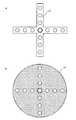
本発明を、図面で示された実施例によって、さらに具体的に説明するが、本発明はこれらの実施例に限定されるものではない。図1は、斜めの管体がその回転平面の半径方向に対して0°に取付具を介して攪拌軸に放射状に配設された本発明の攪拌翼の平面図およびそのB−B切断部断面図である。図2は、本発明の攪拌翼の各種の取付具の平面図である。図3乃至図6は、管体の種々の実施態様を示す。
【0023】
図1は斜めの管体がその回転平面の半径方向に対して0°に取付具を介して攪拌軸に放射状に装着された本発明の攪拌翼を示している。しかして図1において、aはこの攪拌翼の平面図であり、bはaで示された攪拌翼のB−B切断部断面図である。攪拌翼 1 は、4本の取付具 11,11,11,11 および4本の管体 12,12,12,12 から成っている。しかして、取付具 11,11,11,11 は中心角を90°とし、攪拌軸 2 に対して垂直に、中心環 7 により攪拌軸 2 に装着されている。取付具 11 として、穿孔されていない幅の狭い板が使用されている。中心環 7 には攪拌軸 2 が挿通せしめられている。各管体 12 は、各取付具 11 の先端に、傾斜角約45°で攪拌軸 2 に対して斜めに配設され、かつ、その回転平面の半径方向に対して実質的に0°、すなわち、この回転平面の半径方向に、攪拌軸 2 に対して放射状に装着されている。
【0024】
また、管体 12 はほぼ真っ直ぐな円筒であり、その上端はほぼ水平に曲げられており、その先端は水平方向に扁平に潰され上部開口 124 とされている。また、その下端は形状が円の下部開口 125 とされている。管体 12 はその上部開口 124 が下部開口 125 よりも攪拌軸 2 から離間せしめられている。この攪拌翼において、使用時には、管体 12 の上部開口 124 および下部開口 125 は、攪拌翼の回転方向とは関係なく、それぞれ、排出開口および吸入開口とされる。
【0025】
取付具11の前記以外の実施態様として、図2aに示されているように、その形状が平面図として、穿孔された幅の狭い板状体などの2本を同一な回転平面上に互いに直交させることができ、また、図2bに示されているように多孔円板とすることもできる。ここで示された取付具は、その平面を攪拌翼の回転平面と実質的に平行になるように、攪拌軸に装着される。
【0026】
図3乃至図5は、スプレーシャワー型管体を示している。図6は、スプレー型管体を示している。図3乃至図6において、aはこの管体の側面図である。図3においてbは平面図である。図4乃至図6においてbは底面図である。
【0027】
図3で示された管体12の管部126は、側方から見て上方に弯曲せしめられ、上方から見ても小さく弯曲せしめられている。また、管部126の上端部は漏斗状の漏斗部127とされている。上部開口124は長方形で、多孔板で覆われており、また、下部開口125の形状は円である。さらに、上部開口124および下部開口125の開口方向は、それぞれ、斜め上方および水平方向である。
【0028】
図4で示された管体12の管部126は、側方から見て縦長のS字状でその上端部は斜め下方に曲げられており、下方から見て小さい曲率で弯曲せしめられている。また、管部126の上端部は漏斗状とされて漏斗部127とされている。上部開口124は楕円で、多孔板で覆われており、また、下部開口125の形状は円である。さらに上部開口124および下部開口125の開口方向は、それぞれ、斜め下方および水平方向である。
【0029】
図5で示された管体12の管部126は、側方から見て縦長のS字状とされ、下方から見て下部で攪拌軸2に向けて僅かに弯曲せしめられている。また、管部126の上端部は漏斗状の漏斗部127とされている。上部開口124は円で、多孔板で覆われており、下部開口125の形状は円である。さらに、上部開口124および下部開口125の開口方向は、それぞれ、攪拌軸2から遠ざかるような側方および水平方向である。
【0030】
図6で示された管体12の管部126は、側方から見て扁平なS字状とされ、下方から見て下端部が小さい曲率で弯曲せしめられている。この弯曲の方向は、取付具に取付けられた場合の下部開口125が攪拌軸2に接近するような方向である。また、管部126の上端部は塞がれて盲管とされている。この管部126の上端部の下面には多数の孔が穿設され上部開口124とされている。下部開口125の形状は円である。さらに、下部開口125の開口方向は水平方向である。図3乃至図6に示された管体において、管体は下部が上部よりも太くされ、開口面積も下部開口が上部開口よりも大きくされている。
【0031】
【発明の効果】
2種以上の、たとえば、比重が互いに異なる液同士および分散質の含有率が互いに相違する液同士などをそれぞれ効率よく混合することが可能となる。
【図面の簡単な説明】
【図1】 斜めの管体がその回転平面の半径方向に対して0°に取付具を介して攪拌軸に放射状に配設された本発明の攪拌翼を示しており、aはこの攪拌翼の平面図であり、bはaで示された攪拌翼のB−B切断部断面図である。
【図2】 本発明の攪拌翼の取付具の平面図である。
【図3】 本発明の攪拌翼のスプレーシャワー型管体を示し、aおよびbは、それぞれ、側面図および平面図である。
【図4】 本発明の攪拌翼のスプレーシャワー型管体を示し、aおよびbは、それぞれ、側面図および底面図である。
【図5】 本発明の攪拌翼のスプレーシャワー型管体を示し、aおよびbは、それぞれ、側面図および底面図である。
【図6】 本発明の攪拌翼のスプレー型管体を示し、aおよびbは、それぞれ、側面図および底面図である。
【符号の説明】
1 攪拌翼
11 取付具
12 管体
121 直管部
122 曲折部
123 接合点
124 上部開口
125 下部開口
126 管部
127 漏斗部
2 攪拌軸
7 中心環[0001]
[Industrial application fields]
The present invention relates to a stirring blade and a stirring method using the stirring blade. More specifically, the present invention is suitably used for mixing liquids having different specific gravities or mixing liquids having different dispersoid contents. The present invention relates to a stirring blade and a stirring method using the stirring blade.
[0002]
Mixing of liquids with different specific gravities and difficult to mix with each other, suspensions with different dispersoid contents, and dispersoids in the liquid settled during stirring, and the upper and lower parts of the liquid in the tank Mechanical rotary stirring using various stirring blades is also performed when mixing suspensions in which the content of dispersoids differs in the upper and lower directions, such as suspensions in which the content of the dispersoid differs. However, in this case, there is a drawback that a large amount of power is required and the mixing rate does not increase as much as expected for the large power.
[0003]
As a result of earnestly and thoroughly studying the stirring blade and the stirring method in order to efficiently mix two or more kinds of liquids such as suspensions with different specific gravities and suspensions having different dispersoid contents at the top and bottom, The present invention has been reached.
[0004]
[Means and Actions for Solving the Problems]
That is, the first invention has an upper opening and a lower opening at each of an upper end and a lower end, and one or more hollows in which the sizes of the upper opening and the lower opening are made different or equal to each other. tube is (hereinafter referred to as tube), obliquely with respect to 撹拌軸fixture which is allowed to attached to a stirring shaft, and is disposed radially, the liquid in each stirring vessel an upper opening and a lower opening to face in the upper and in the lower, by the tube body is rotated around the said stirring shaft around the stirring shaft, the one of the liquid in the agitation tank from one opening of the tube member The stirring blade is characterized in that it is supplied into a pipe body, passed through the pipe body, and discharged from the other opening of the pipe body into the other liquid.
[0005]
Further, the second invention is a method of stirring and mixing a liquid to be mixed in a stirring tank, wherein the tube of the stirring blade of the first invention is submerged in the liquid in the stirring tank, and the upper opening of the tube of the stirring blade The upper and lower openings of the liquid in the agitation tank are brought into contact with the upper and lower parts of the liquid in the agitation tank by the pipes of the agitation blades, respectively. The tube body is rotated around the stirring shaft around the stirring shaft, and the liquid in the stirring tank is stirred by the pipe body of the stirring blade, and one liquid in the stirring tank is removed from one opening of the tube body. Supply the liquid into the pipe body, let it pass through the pipe body, discharge it into the other liquid from the other opening of the pipe body, mix the upper and lower parts of the liquid in the stirring tank, and mix the liquid to be mixed It is the stirring method characterized by doing.
[0006]
The fixture is attached to the agitation shaft, and one or more tubes are attached to the fixture. The mounting tool is preferably a rod-shaped body, a square member, a steel plate, a plate-shaped body that is not perforated, etc., but a plate-shaped body having a large number of holes (hereinafter sometimes referred to as a porous plate-shaped body) is used. Ru can also. These non-perforated plates and perforated plates are preferably attached to the stirring shaft so that the fluid resistance becomes as small as possible when rotating in the liquid. In addition, when the surface of the plate-shaped body which is not pierced is used vertically in the liquid (perpendicular to the rotation plane of the stirring blade), it is preferable that the width is narrow.
[0007]
These rod-shaped body, square bar, steel plate, perforated plate and unperforated plate-shaped body are positioned substantially on the diameter of the rotation plane. In addition, the number of these rod-like bodies, square bars, mold steel, perforated plates and unperforated plate-like bodies may be one, but may be plural, and in the case of plural, they are arranged on the same rotation plane. They may be provided, or may be arranged on different rotation planes. These fixtures are disposed so as to be substantially orthogonal to the stirring shaft. When there are a plurality of tubes, the interval between the tubes is appropriately selected depending on the viscosity of the liquid, the thickness of the tube, the diameter of the tank body of the stirring tank, the angle between the stirring shaft and the pipe, and the like. The
[0008]
The pipe body can be a straight pipe as a whole, but the upper part can be a straight pipe part, the lower part can be a bent part, or the overall shape at the side can be substantially S-shaped. Furthermore, the upper part of the straight pipe portion can be bent in any direction, such as obliquely upward or obliquely downward, further toward the peripheral wall of the agitation tank, or toward the agitation shaft, if desired. .
[0009]
The bent portion of the lower part of the tube can be formed by bending the tube, or another tube can be formed by connecting to the tip of the straight tube of the tube, for example, by welding or screwing. it can. The bent portion of the tubular body is substantially 0 to 90 ° with respect to the radial direction of the rotation plane at the junction point with the straight pipe portion, ie, in the radial direction of the rotation plane. Formed along the circumference having a radius from the rotation axis to the joining point, or along the tangential direction of the circumference, or the entire tube is formed from the stirring shaft to the tube. It can be bent along a circular arc of a circle having a radius substantially equal to the distance to the mounting position. Further, the entire tube body is formed as a straight tube as a whole when viewed from above or below the rotation plane, and is formed radially with respect to the stirring axis, preferably substantially 0 ° with respect to the radial direction of the rotation plane of the tube body . It provided to the fixture.
[0010]
The upper end and the lower end of the tube body face the liquid in the stirring tank as an upper opening and a lower opening, respectively. When a plurality of tubular bodies are provided, the upper openings and the lower openings may be opened in substantially the same rotation plane or different rotation planes, respectively.
[0011]
The shape of the upper opening of the tube is not particularly limited, but usually, for example, a circle such as a circle, an ellipse, and an ellipse, and a polygon such as a triangle, square, rectangle, rhombus, hexagon, and octagon Is done. The upper opening can be closed with a perforated plate, and if desired, the upper opening can be formed into a funnel shape to form a shower spray-type tube. The upper end portion can be closed to form a blind tube, and the upper end portion can be provided with a plurality of holes as an upper opening to form a spray-type tube. There is no particular limitation on the shape of the lower opening of the tube and the cross section of the tube, but usually, for example, circles such as circles, ellipses and ellipses, and triangles, squares, rectangles, rhombuses, hexagons and It is assumed to be a polygon such as an octagon.
[0012]
Each shape of the upper opening and the lower opening of the tube may be the same as or different from each other. Also, the liquid resistance can be reduced by making the tip of one of the openings of the tubular body preceded during stirring thin and sharp.
[0013]
In the tubular body, the opening areas of the upper opening and the lower opening may be substantially equal to each other or may be different from each other, but the latter is preferable in practice. In the latter case, the ratio of the two openings is arbitrarily selected depending on the type of liquid to be mixed and the operating conditions. In the latter case, during use, any opening may be used as an opening for taking in liquid (hereinafter also referred to as suction opening) or an opening for discharging liquid (hereinafter also referred to as discharging opening). Although practical, the suction opening is usually enlarged . In the tubular body, when an opening covered with a perforated plate and a large number of holes are openings, the area of the opening is the total area of the holes.
[0014]
One or a plurality of tubes is attached again and again, Ru is disposed obliquely to the stirring shaft. Also, when a plurality of pipes are arranged obliquely with respect to the stirring shaft, the angle may be the same as each other or may be different from each other. The angle of inclination of the tube inclined with respect to the stirring axis (the angle between the stirring shaft and the tube) varies depending on the viscosity of the liquid and the thickness of the tube, and cannot be specified in general. For example, it is preferably about 15 to 75 °. Moreover, in order to adjust the magnitude | size of an inclination angle arbitrarily, a tubular body can also be rotatably attached to a fixture. The plurality of tubes disposed in one fixture are usually the same in length, thickness, shape, type, etc., but can also be different.
[0015]
In the present invention, by rotating the tube around the stirring shaft about the stirring shaft (rotating shaft), the liquid in the stirring vessel moves in the tube according to Bernoulli's theorem and / or by centrifugal force. I'm damned.
[0016]
The stirring blade of the present invention is used by being fixed to the stirring shaft by the fixture or slidably mounted. The fixing means is not particularly limited, and may be any one of, for example, fitting, screwing, welding, and adhesion. In addition, in order to slidably mount, for example, a groove or protrusion or a protrusion is provided on the surface of the stirring shaft along the long axis, and the groove or protrusion on the surface of the stirring shaft is provided on the fixture. Alternatively, it is possible to provide protrusions or protrusions or grooves that can be fitted and slid with the protrusions.
[0017]
Furthermore, the fixture slidably attached to the stirring shaft can be moved automatically or manually. For example, the tube body can be moved up and down in the liquid by a remote operation from outside the stirring tank and stopped at a predetermined position in the liquid. Alternatively, the pipe body can be manually moved up and down in the liquid by suspending the fixture with a wire connected to the outside of the stirring tank and tensioning or relaxing the wire outside the stirring tank.
[0018]
In the stirring method of the present invention, the rotational speed of the stirring blade can be appropriately selected depending on the kind of the liquid to be mixed, the length and the number of the pipes, etc., but practically, for example, the speed of the tip of the pipe is 2. It is preferably about 5 meters / second or more.
[0019]
In the agitating blade of the present invention, the upper and lower openings of the tubes radially arranged at 0 ° with respect to the radial direction of the plane of rotation face the upper and lower parts of the liquid in the agitation tank, respectively. In addition, the upper and lower parts of the liquid in the agitation tank are connected to each other by the tube (hereinafter also referred to as the upper liquid and lower liquid, respectively), and the agitation blade is rotated around the agitation axis around the agitation axis. As a result, the liquid in the agitation tank is agitated by the tube of the agitation blade, and the opening close to the center of the rotation plane and the opening on the circumferential side of the rotation plane are independent of the rotation direction. And one discharge liquid in the stirring tank is supplied to the pipe body from the suction opening of the pipe body, and the liquid is passed through the pipe body and discharged from the discharge opening of the pipe body into the other liquid. Upper and lower parts of the liquid in the stirring tank As a result, both liquids are mixed.
[0020]
Examples of liquids to be mixed include liquids and suspensions composed of liquids having different specific gravities and difficult to mix. The upper part and the lower part of the liquid in the stirring tank are a liquid having a small specific gravity and a liquid having a large specific gravity, respectively, in the former, and a liquid having a small content of dispersoid and a content of the dispersoid, respectively, in the latter. Large liquid. Thus, in the latter case, in addition to two or more types of suspensions having different dispersoid contents, the content of dispersoids in the upper part and the lower part is caused by sedimentation of the dispersoid during stirring of one kind of suspension. A liquid separated into a suspension having a relatively low content and a suspension having a relatively high dispersoid content is also included.
[0021]
The stirring blades of the present invention are conventional stirring blades such as turbine blades, propellers, angled flat blades, pitched flat blades, flat blade disk turbines, flat blades, curved blades, fiddler blades and bull margin blades. It can be used in combination with stirring means such as stirring by jet jet and / or aeration stirring, and is preferred. The fixture itself can also act as a stirring blade.
[0022]
【Example】
The present invention will be described more specifically with reference to the embodiments shown in the drawings, but the present invention is not limited to these embodiments. FIG. 1 is a plan view of a stirring blade of the present invention in which an oblique tube body is radially disposed on a stirring shaft through a fixture at 0 ° with respect to the radial direction of its rotation plane, and its BB cut portion. It is sectional drawing. FIG. 2 is a plan view of various fixtures of the stirring blade of the present invention. 3-6 show various embodiments of the tube.
[0023]
FIG. 1 shows an agitating blade of the present invention in which an oblique tube body is radially attached to an agitating shaft through a fixture at 0 ° with respect to the radial direction of the plane of rotation. 1. In FIG. 1, a is a plan view of the stirring blade, and b is a cross-sectional view of the stirring blade taken along the line B-B indicated by a. The stirring blade 1 is composed of four
[0024]
The
[0025]
As an embodiment other than the
[0026]
3 to 5 show a spray shower tube. FIG. 6 shows a spray tube. 3 to 6 , a is a side view of the tube. In FIG. 3 , b is a plan view. 4 to 6 , b is a bottom view.
[0027]
The
[0028]
The
[0029]
The
[0030]
The
[0031]
【The invention's effect】
Two or more kinds of liquids having different specific gravities and liquids having different dispersoid contents, for example, can be efficiently mixed.
[Brief description of the drawings]
FIG. 1 shows a stirring blade of the present invention in which an oblique tube body is radially arranged on a stirring shaft through a fixture at 0 ° with respect to the radial direction of the plane of rotation; FIG. 4B is a cross-sectional view taken along the line BB of the stirring blade indicated by a.
FIG. 2 is a plan view of a stirring blade attachment according to the present invention.
FIG. 3 shows a spray shower type tubular body of a stirring blade of the present invention, wherein a and b are a side view and a plan view, respectively.
FIG. 4 shows a spray shower type tubular body of a stirring blade of the present invention, wherein a and b are a side view and a bottom view, respectively.
FIG. 5 shows a spray shower type tubular body of a stirring blade of the present invention, wherein a and b are a side view and a bottom view, respectively.
FIG. 6 shows a spray-type tube of a stirring blade of the present invention, wherein a and b are a side view and a bottom view, respectively.
[Explanation of symbols]
1 Stirring blade
11 Fitting
12 tube
121 Straight pipe
122 Turn part
123 junction
124 Top opening
125 Bottom opening
126 pipe
127 Funnel
2 Stirring shaft
7 Central ring
Claims (5)
Priority Applications (1)
| Application Number | Priority Date | Filing Date | Title |
|---|---|---|---|
| JP2001261082A JP3677227B2 (en) | 1993-03-31 | 2001-08-30 | Stirring blade and stirring method |
Applications Claiming Priority (3)
| Application Number | Priority Date | Filing Date | Title |
|---|---|---|---|
| JP9512893 | 1993-03-31 | ||
| JP5-95128 | 1993-03-31 | ||
| JP2001261082A JP3677227B2 (en) | 1993-03-31 | 2001-08-30 | Stirring blade and stirring method |
Related Parent Applications (1)
| Application Number | Title | Priority Date | Filing Date |
|---|---|---|---|
| JP05479994A Division JP3253212B2 (en) | 1993-03-31 | 1994-03-02 | Stirring blade and stirring method |
Publications (2)
| Publication Number | Publication Date |
|---|---|
| JP2002119838A JP2002119838A (en) | 2002-04-23 |
| JP3677227B2 true JP3677227B2 (en) | 2005-07-27 |
Family
ID=14129191
Family Applications (2)
| Application Number | Title | Priority Date | Filing Date |
|---|---|---|---|
| JP05479994A Expired - Lifetime JP3253212B2 (en) | 1993-03-31 | 1994-03-02 | Stirring blade and stirring method |
| JP2001261082A Expired - Lifetime JP3677227B2 (en) | 1993-03-31 | 2001-08-30 | Stirring blade and stirring method |
Family Applications Before (1)
| Application Number | Title | Priority Date | Filing Date |
|---|---|---|---|
| JP05479994A Expired - Lifetime JP3253212B2 (en) | 1993-03-31 | 1994-03-02 | Stirring blade and stirring method |
Country Status (4)
| Country | Link |
|---|---|
| EP (2) | EP0861685B1 (en) |
| JP (2) | JP3253212B2 (en) |
| DE (2) | DE69432802T2 (en) |
| DK (2) | DK0861685T3 (en) |
Families Citing this family (30)
| Publication number | Priority date | Publication date | Assignee | Title |
|---|---|---|---|---|
| DE69810067T2 (en) | 1997-11-14 | 2003-10-02 | Kansai Chemical Engineering Co., Ltd. | Device and method for liquid ejection |
| AU754116B2 (en) * | 1999-02-22 | 2002-11-07 | Kansai Chemical Engineering Co., Ltd. | Liquid ejection apparatus and liquid ejection method |
| CA2298879C (en) | 1999-02-22 | 2004-09-14 | Hideo Noda | Liquid ejection apparatus and liquid ejection method |
| JP3525126B2 (en) * | 1999-08-25 | 2004-05-10 | 関西化学機械製作株式会社 | Crystallizer and crystallization method |
| DK1329257T3 (en) * | 2000-09-28 | 2006-07-31 | Kansai Chem Eng | Heat transfer device |
| JP4882156B2 (en) * | 2001-03-30 | 2012-02-22 | Dic株式会社 | Production method of polyurethane water dispersion |
| EP1645612A2 (en) | 2004-09-15 | 2006-04-12 | Konica Minolta Medical & Graphic, Inc. | Radiographic imaging device and radiographic imaging method |
| FR2892642B1 (en) * | 2005-10-28 | 2007-11-30 | Prosign Sa | FONDOR FOR HOMOGENIZING AND HEATING A PRODUCT, IN PARTICULAR A GROUND MARKING COMPOSITION |
| JP5140566B2 (en) * | 2008-12-01 | 2013-02-06 | 関西化学機械製作株式会社 | Stirrer |
| JP5288179B2 (en) * | 2008-12-16 | 2013-09-11 | 大日本印刷株式会社 | Stirrer |
| JP5178629B2 (en) * | 2009-05-20 | 2013-04-10 | 株式会社仲田コーティング | Agitator cleaning equipment |
| DE102009054202B3 (en) * | 2009-11-21 | 2011-06-30 | Feldhans-Becker, Dominik, 47665 | Mechanism for adjusting mixing coils in mixing machine for mixing of powdery, granular, plastic and fluid mass, has concave calotte shell surface pressed against convex calotte shell surface and formed complementary to concave surface |
| JP6109006B2 (en) * | 2013-08-07 | 2017-04-05 | 住友重機械プロセス機器株式会社 | Stirrer |
| JP2015047540A (en) * | 2013-08-30 | 2015-03-16 | 株式会社石井鐵工所 | Centrifugal agitator |
| CN104437172A (en) * | 2014-12-12 | 2015-03-25 | 成都艺辰德迅科技有限公司 | Automatic control cream stirrer device adopting Internet of things |
| CN108786545A (en) * | 2018-06-21 | 2018-11-13 | 四川汇宇生物技术有限公司 | A kind of gelatin solution blender |
| CN109126599A (en) * | 2018-09-14 | 2019-01-04 | 蒋友明 | Fish meal preparation facilities |
| CN109224926B (en) * | 2018-10-24 | 2021-09-14 | 吉安螃蟹王国科技有限公司 | Scalable manual paint mixing of colors agitated vessel of preventing layering |
| JP6958879B2 (en) * | 2019-04-26 | 2021-11-02 | 泰喜物産株式会社 | A stirrer used for continuous production of tofu and a continuous production device for tofu provided with the stirrer. |
| CN110652903A (en) * | 2019-09-24 | 2020-01-07 | 广东东荣金属制品有限公司 | Ultra-high-speed rotating multi-cutter-head gas-liquid cutting mixing oxygenator |
| CN112831407A (en) * | 2020-12-25 | 2021-05-25 | 江苏大明生物工程装备有限公司 | Large-scale aerobic fermentation jar with agitator |
| JP7121958B1 (en) * | 2021-03-17 | 2022-08-19 | 関西化学機械製作株式会社 | Reactor and method for producing reaction product using same |
| JP7169602B1 (en) | 2021-09-29 | 2022-11-11 | 関西化学機械製作株式会社 | DISPERSION DEVICE AND REACTOR USING THE SAME |
| JP7252579B1 (en) * | 2021-12-17 | 2023-04-05 | 関西化学機械製作株式会社 | Process liquid circulation method, dispersion device and process liquid circulation apparatus used therefor |
| CN114405339A (en) * | 2022-01-10 | 2022-04-29 | 绍兴市质量技术监督检测院 | Mixing preparation facilities of dyestuff |
| JP7126183B1 (en) | 2022-01-25 | 2022-08-26 | 関西化学機械製作株式会社 | DISPERSION DEVICE AND DISPERSION APPARATUS USING THE SAME |
| CN114505286B (en) * | 2022-02-14 | 2023-04-21 | 广西力合城市矿产再生资源科技有限公司 | Stainless steel waste residue recycling equipment and process |
| JPWO2023243335A1 (en) * | 2022-06-14 | 2023-12-21 | ||
| CN117448136B (en) * | 2023-11-20 | 2024-06-07 | 品源(随州)现代农业发展有限公司 | Mushroom sauce fermentation device and process |
| CN118217872B (en) * | 2024-05-27 | 2024-07-12 | 中国石油大学(华东) | Dynamic sustainable generation and injection device for viscoelastic foam and application thereof |
Family Cites Families (15)
| Publication number | Priority date | Publication date | Assignee | Title |
|---|---|---|---|---|
| DE185488C (en) * | ||||
| US2143652A (en) * | 1936-09-16 | 1939-01-10 | Gaertner Moritz | Positively controlled vertical agitator and conditioner |
| US3341450A (en) * | 1965-10-24 | 1967-09-12 | Yeomans Brothers Co | Gasification apparatus and method |
| DE1658067A1 (en) * | 1967-10-13 | 1970-07-02 | Friehe Dipl Ing Bernhard | Ventilation device for the biological purification of waste water |
| DE1658115A1 (en) * | 1967-11-15 | 1970-08-20 | Passavant Werke | Device for introducing gases, e.g. air, into sewage or similar liquids |
| CH463409A (en) * | 1968-05-28 | 1968-09-30 | Kaelin J R | Surface aerators for circulating and aerating liquids, in particular for waste water purification systems |
| US3591149A (en) * | 1969-01-16 | 1971-07-06 | Passavant Werke | Aeration apparatus |
| DE1941146C3 (en) * | 1969-08-13 | 1978-12-21 | Passavant-Werke Michelbacher Huette, 6209 Aarbergen | Blade for ventilation rotors |
| DE1963614A1 (en) * | 1969-12-19 | 1971-06-24 | Bamag Verfahrenstechnik Gmbh | Surface gasifier or aerator for liquids |
| DE1964125A1 (en) * | 1969-12-22 | 1971-06-24 | Babcock & Wilcox Ag | Surface aerator for liquids |
| DE2409549A1 (en) * | 1974-02-28 | 1975-09-11 | Sotralentz Sa | DEVICE FOR SPRAYING WATER INTO THE AIR |
| GB1600283A (en) * | 1977-07-05 | 1981-10-14 | Biomechanics Ltd | Apparatus for anaerobic digestion of biodegradable waste material |
| CH630268A5 (en) * | 1978-06-12 | 1982-06-15 | Kaelin J R | SURFACE VENTILATOR. |
| DE2844038C2 (en) * | 1978-10-09 | 1985-04-04 | Selwig & Lange Maschinenfabrik, 3300 Braunschweig | Device for the intimate mixing of two material components, at least one of which is liquid |
| SU914077A1 (en) * | 1980-02-27 | 1982-03-23 | Kishinevskij Polt Inst | Apparatus for ajitating liquids |
-
1994
- 1994-03-02 JP JP05479994A patent/JP3253212B2/en not_active Expired - Lifetime
- 1994-03-23 DK DK98107451T patent/DK0861685T3/en active
- 1994-03-23 EP EP98107451A patent/EP0861685B1/en not_active Expired - Lifetime
- 1994-03-23 DE DE69432802T patent/DE69432802T2/en not_active Expired - Lifetime
- 1994-03-23 EP EP94104601A patent/EP0619136B1/en not_active Expired - Lifetime
- 1994-03-23 DE DE69419444T patent/DE69419444T2/en not_active Expired - Lifetime
- 1994-03-23 DK DK94104601T patent/DK0619136T3/en active
-
2001
- 2001-08-30 JP JP2001261082A patent/JP3677227B2/en not_active Expired - Lifetime
Also Published As
| Publication number | Publication date |
|---|---|
| JP3253212B2 (en) | 2002-02-04 |
| DE69432802D1 (en) | 2003-07-10 |
| EP0861685A3 (en) | 2000-02-09 |
| EP0619136A1 (en) | 1994-10-12 |
| DK0619136T3 (en) | 1999-11-29 |
| EP0861685B1 (en) | 2003-06-04 |
| DE69419444T2 (en) | 2000-03-30 |
| JPH06335627A (en) | 1994-12-06 |
| EP0861685A2 (en) | 1998-09-02 |
| DE69432802T2 (en) | 2004-05-06 |
| JP2002119838A (en) | 2002-04-23 |
| DE69419444D1 (en) | 1999-08-19 |
| DK0861685T3 (en) | 2003-06-23 |
| EP0619136B1 (en) | 1999-07-14 |
Similar Documents
| Publication | Publication Date | Title |
|---|---|---|
| JP3677227B2 (en) | Stirring blade and stirring method | |
| JP3797644B2 (en) | How to squirt liquid | |
| US5198156A (en) | Agitators | |
| US6334704B2 (en) | Liquid ejection apparatus and liquid ejection method | |
| FI89246B (en) | OMROERNINGSIMPELLERAPPARAT | |
| EP0347618B1 (en) | Mixing apparatus | |
| CA2235045C (en) | Impeller assembly with asymmetric concave blades | |
| EP0441505A1 (en) | Agitators | |
| JPS6253213B2 (en) | ||
| RU2000108708A (en) | GLASS COATED DISPERSING GAS, MIXER | |
| EP0234768B1 (en) | Agitator | |
| JP2902798B2 (en) | Mixing device for mold material | |
| EP0338967A1 (en) | Apparatus for treating slurry by gas-liquid contact method | |
| JP2000308816A (en) | Liquid jetting device and liquid jetting method | |
| JP4328904B2 (en) | Gas-liquid mixing device | |
| JP6189202B2 (en) | Stirrer | |
| JP4766905B2 (en) | Paddle blade and stirring device provided with the paddle blade | |
| JPH078776A (en) | Agitating blade | |
| JP3902869B2 (en) | Stirrer | |
| JPH08182924A (en) | Agitating blade | |
| JPH0222032Y2 (en) | ||
| JP2004121950A (en) | Immersion type medium dispersing apparatus | |
| JPH02280823A (en) | Gas-liquid stirring blade apparatus | |
| JPH1120893A (en) | Stirrer for cwm reservoir | |
| JP2006043668A (en) | Fluid stirring device, turbine-type stirrer and baffle used therefor |
Legal Events
| Date | Code | Title | Description |
|---|---|---|---|
| A131 | Notification of reasons for refusal |
Free format text: JAPANESE INTERMEDIATE CODE: A131 Effective date: 20041102 |
|
| A521 | Written amendment |
Free format text: JAPANESE INTERMEDIATE CODE: A523 Effective date: 20041224 |
|
| A131 | Notification of reasons for refusal |
Free format text: JAPANESE INTERMEDIATE CODE: A131 Effective date: 20050201 |
|
| A521 | Written amendment |
Free format text: JAPANESE INTERMEDIATE CODE: A523 Effective date: 20050330 |
|
| TRDD | Decision of grant or rejection written | ||
| A01 | Written decision to grant a patent or to grant a registration (utility model) |
Free format text: JAPANESE INTERMEDIATE CODE: A01 Effective date: 20050426 |
|
| A61 | First payment of annual fees (during grant procedure) |
Free format text: JAPANESE INTERMEDIATE CODE: A61 Effective date: 20050506 |
|
| R150 | Certificate of patent or registration of utility model |
Free format text: JAPANESE INTERMEDIATE CODE: R150 |
|
| RD02 | Notification of acceptance of power of attorney |
Free format text: JAPANESE INTERMEDIATE CODE: R3D02 |
|
| FPAY | Renewal fee payment (event date is renewal date of database) |
Free format text: PAYMENT UNTIL: 20090513 Year of fee payment: 4 |
|
| FPAY | Renewal fee payment (event date is renewal date of database) |
Free format text: PAYMENT UNTIL: 20100513 Year of fee payment: 5 |
|
| FPAY | Renewal fee payment (event date is renewal date of database) |
Free format text: PAYMENT UNTIL: 20110513 Year of fee payment: 6 |
|
| FPAY | Renewal fee payment (event date is renewal date of database) |
Free format text: PAYMENT UNTIL: 20110513 Year of fee payment: 6 |
|
| RD02 | Notification of acceptance of power of attorney |
Free format text: JAPANESE INTERMEDIATE CODE: R3D02 |
|
| FPAY | Renewal fee payment (event date is renewal date of database) |
Free format text: PAYMENT UNTIL: 20120513 Year of fee payment: 7 |
|
| FPAY | Renewal fee payment (event date is renewal date of database) |
Free format text: PAYMENT UNTIL: 20130513 Year of fee payment: 8 |
|
| FPAY | Renewal fee payment (event date is renewal date of database) |
Free format text: PAYMENT UNTIL: 20140513 Year of fee payment: 9 |
|
| EXPY | Cancellation because of completion of term |