JP3677199B2 - Push button switch and teaching pendant with the same - Google Patents
Push button switch and teaching pendant with the same Download PDFInfo
- Publication number
- JP3677199B2 JP3677199B2 JP2000232229A JP2000232229A JP3677199B2 JP 3677199 B2 JP3677199 B2 JP 3677199B2 JP 2000232229 A JP2000232229 A JP 2000232229A JP 2000232229 A JP2000232229 A JP 2000232229A JP 3677199 B2 JP3677199 B2 JP 3677199B2
- Authority
- JP
- Japan
- Prior art keywords
- push button
- state
- pressing
- button switch
- contact
- Prior art date
- Legal status (The legal status is an assumption and is not a legal conclusion. Google has not performed a legal analysis and makes no representation as to the accuracy of the status listed.)
- Expired - Fee Related
Links
Images


Classifications
-
- H—ELECTRICITY
- H01—ELECTRIC ELEMENTS
- H01H—ELECTRIC SWITCHES; RELAYS; SELECTORS; EMERGENCY PROTECTIVE DEVICES
- H01H13/00—Switches having rectilinearly-movable operating part or parts adapted for pushing or pulling in one direction only, e.g. push-button switch
- H01H13/02—Details
- H01H13/26—Snap-action arrangements depending upon deformation of elastic members
- H01H13/28—Snap-action arrangements depending upon deformation of elastic members using compression or extension of coil springs
-
- G—PHYSICS
- G05—CONTROLLING; REGULATING
- G05B—CONTROL OR REGULATING SYSTEMS IN GENERAL; FUNCTIONAL ELEMENTS OF SUCH SYSTEMS; MONITORING OR TESTING ARRANGEMENTS FOR SUCH SYSTEMS OR ELEMENTS
- G05B19/00—Programme-control systems
-
- H—ELECTRICITY
- H01—ELECTRIC ELEMENTS
- H01H—ELECTRIC SWITCHES; RELAYS; SELECTORS; EMERGENCY PROTECTIVE DEVICES
- H01H13/00—Switches having rectilinearly-movable operating part or parts adapted for pushing or pulling in one direction only, e.g. push-button switch
- H01H13/50—Switches having rectilinearly-movable operating part or parts adapted for pushing or pulling in one direction only, e.g. push-button switch having a single operating member
- H01H13/506—Switches having rectilinearly-movable operating part or parts adapted for pushing or pulling in one direction only, e.g. push-button switch having a single operating member with a make-break action in a single operation
-
- H—ELECTRICITY
- H01—ELECTRIC ELEMENTS
- H01H—ELECTRIC SWITCHES; RELAYS; SELECTORS; EMERGENCY PROTECTIVE DEVICES
- H01H13/00—Switches having rectilinearly-movable operating part or parts adapted for pushing or pulling in one direction only, e.g. push-button switch
- H01H13/50—Switches having rectilinearly-movable operating part or parts adapted for pushing or pulling in one direction only, e.g. push-button switch having a single operating member
- H01H13/52—Switches having rectilinearly-movable operating part or parts adapted for pushing or pulling in one direction only, e.g. push-button switch having a single operating member the contact returning to its original state immediately upon removal of operating force, e.g. bell-push switch
-
- H—ELECTRICITY
- H01—ELECTRIC ELEMENTS
- H01H—ELECTRIC SWITCHES; RELAYS; SELECTORS; EMERGENCY PROTECTIVE DEVICES
- H01H13/00—Switches having rectilinearly-movable operating part or parts adapted for pushing or pulling in one direction only, e.g. push-button switch
- H01H13/50—Switches having rectilinearly-movable operating part or parts adapted for pushing or pulling in one direction only, e.g. push-button switch having a single operating member
- H01H13/64—Switches having rectilinearly-movable operating part or parts adapted for pushing or pulling in one direction only, e.g. push-button switch having a single operating member wherein the switch has more than two electrically distinguishable positions, e.g. multi-position push-button switches
- H01H13/66—Switches having rectilinearly-movable operating part or parts adapted for pushing or pulling in one direction only, e.g. push-button switch having a single operating member wherein the switch has more than two electrically distinguishable positions, e.g. multi-position push-button switches the operating member having only two positions
-
- H—ELECTRICITY
- H01—ELECTRIC ELEMENTS
- H01H—ELECTRIC SWITCHES; RELAYS; SELECTORS; EMERGENCY PROTECTIVE DEVICES
- H01H13/00—Switches having rectilinearly-movable operating part or parts adapted for pushing or pulling in one direction only, e.g. push-button switch
- H01H13/70—Switches having rectilinearly-movable operating part or parts adapted for pushing or pulling in one direction only, e.g. push-button switch having a plurality of operating members associated with different sets of contacts, e.g. keyboard
- H01H13/72—Switches having rectilinearly-movable operating part or parts adapted for pushing or pulling in one direction only, e.g. push-button switch having a plurality of operating members associated with different sets of contacts, e.g. keyboard wherein the switch has means for limiting the number of operating members that can concurrently be in the actuated position
-
- H—ELECTRICITY
- H01—ELECTRIC ELEMENTS
- H01H—ELECTRIC SWITCHES; RELAYS; SELECTORS; EMERGENCY PROTECTIVE DEVICES
- H01H15/00—Switches having rectilinearly-movable operating part or parts adapted for actuation in opposite directions, e.g. slide switch
- H01H15/02—Details
- H01H15/06—Movable parts; Contacts mounted thereon
- H01H15/10—Operating parts
- H01H15/102—Operating parts comprising cam devices
- H01H15/107—Operating parts comprising cam devices actuating conventional selfcontained microswitches
-
- H—ELECTRICITY
- H01—ELECTRIC ELEMENTS
- H01H—ELECTRIC SWITCHES; RELAYS; SELECTORS; EMERGENCY PROTECTIVE DEVICES
- H01H9/00—Details of switching devices, not covered by groups H01H1/00 - H01H7/00
- H01H2009/0083—Details of switching devices, not covered by groups H01H1/00 - H01H7/00 using redundant components, e.g. two pressure tubes for pressure switch
-
- H—ELECTRICITY
- H01—ELECTRIC ELEMENTS
- H01H—ELECTRIC SWITCHES; RELAYS; SELECTORS; EMERGENCY PROTECTIVE DEVICES
- H01H2225/00—Switch site location
- H01H2225/008—Two different sites for one circuit, e.g. for safety
-
- H—ELECTRICITY
- H01—ELECTRIC ELEMENTS
- H01H—ELECTRIC SWITCHES; RELAYS; SELECTORS; EMERGENCY PROTECTIVE DEVICES
- H01H2300/00—Orthogonal indexing scheme relating to electric switches, relays, selectors or emergency protective devices covered by H01H
- H01H2300/026—Application dead man switch: power must be interrupted on release of operating member
-
- H—ELECTRICITY
- H01—ELECTRIC ELEMENTS
- H01H—ELECTRIC SWITCHES; RELAYS; SELECTORS; EMERGENCY PROTECTIVE DEVICES
- H01H2300/00—Orthogonal indexing scheme relating to electric switches, relays, selectors or emergency protective devices covered by H01H
- H01H2300/028—Application dead man switch, i.e. power being interrupted by panic reaction of operator, e.g. further pressing down push button
-
- H—ELECTRICITY
- H01—ELECTRIC ELEMENTS
- H01H—ELECTRIC SWITCHES; RELAYS; SELECTORS; EMERGENCY PROTECTIVE DEVICES
- H01H3/00—Mechanisms for operating contacts
- H01H3/001—Means for preventing or breaking contact-welding
-
- H—ELECTRICITY
- H01—ELECTRIC ELEMENTS
- H01H—ELECTRIC SWITCHES; RELAYS; SELECTORS; EMERGENCY PROTECTIVE DEVICES
- H01H3/00—Mechanisms for operating contacts
- H01H3/02—Operating parts, i.e. for operating driving mechanism by a mechanical force external to the switch
- H01H3/12—Push-buttons
- H01H3/122—Push-buttons with enlarged actuating area, e.g. of the elongated bar-type; Stabilising means therefor
-
- H—ELECTRICITY
- H01—ELECTRIC ELEMENTS
- H01H—ELECTRIC SWITCHES; RELAYS; SELECTORS; EMERGENCY PROTECTIVE DEVICES
- H01H9/00—Details of switching devices, not covered by groups H01H1/00 - H01H7/00
- H01H9/02—Bases, casings, or covers
- H01H9/0214—Hand-held casings
-
- H—ELECTRICITY
- H01—ELECTRIC ELEMENTS
- H01H—ELECTRIC SWITCHES; RELAYS; SELECTORS; EMERGENCY PROTECTIVE DEVICES
- H01H9/00—Details of switching devices, not covered by groups H01H1/00 - H01H7/00
- H01H9/18—Distinguishing marks on switches, e.g. for indicating switch location in the dark; Adaptation of switches to receive distinguishing marks
- H01H9/181—Distinguishing marks on switches, e.g. for indicating switch location in the dark; Adaptation of switches to receive distinguishing marks using a programmable display, e.g. LED or LCD
Landscapes
- Physics & Mathematics (AREA)
- General Physics & Mathematics (AREA)
- Engineering & Computer Science (AREA)
- Automation & Control Theory (AREA)
- Push-Button Switches (AREA)
- Manipulator (AREA)
Description
【0001】
【発明の属する技術分野】
この発明は、押ボタンの押し込み量が増加するにつれて、第1のOFF状態からON状態となり、さらに押し込むと第2のOFF状態に移行する押しボタンスイッチ及びこれを備えた教示用ペンダントに関する。
【0002】
【従来の技術】
例えば、ロボット等のNC制御の機械に対して手動操作を行う際、操作者は危険区域内に入って作業を行う場合が多く、このような場合に、機械との接触による作業中の事故を未然に回避するため、いわゆるイネーブルスイッチ(あるいはデッドマンスイッチ)と呼ばれる押しボタンスイッチを備えた教示ペンダントが用いられている。
【0003】
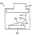
図34に示すように、この教示ペンダント600は、制御装置に接続することにより、ロボットにプログラムを教示したり、あるいはロボットを作動させたりすることのできる携帯用ユニットであって、主面側に配置された入力用キーボード601と、一側面に配置された押しボタンスイッチ(イネーブルスイッチ)602とを有している。なお、押しボタンスイッチ602は教示ペンダント600の裏面側に配置される場合もある。また教示ペンダント600は、図示しない制御装置に接続される信号用ケーブル603を有している。
【0004】
このような教示ペンダントに配設される押しボタンスイッチとしては、例えば図35に示すようなスナップアクション型と呼ばれる押しボタンスイッチが用いられる。
【0005】
この押しボタンスイッチ602は、同図に示すように、押ボタン605と、これに対向配置されたマイクロスイッチ606とを有している。押ボタン605の下面には、下方に延びる板ばね607が設けられており、マイクロスイッチ606の上面には、ばね性を有する押圧板608及びアクチュエータ609が設けられている。板ばね607の先端には、折曲げ部607aが形成されている。
【0006】
押しボタンスイッチ602を使用する際には、まず、押しボタンスイッチ602が組み込まれた教示ペンダント600を、手動操作すべき機械の制御盤に信号用ケーブル603を介して接続する。このとき、押しボタンスイッチ602がOFF状態にあれば、教示ペンダント600のキーボード601を操作してもキー入力されることはない。
【0007】
次に、押ボタン605を押し込むと、図36に示すように、押ボタン605とともに移動する板ばね607の折曲げ部607aがマイクロスイッチ606の押圧板608と係合するとともに、押圧板608が下方に弾性変形してアクチュエータ609を押圧する。これにより、アクチュエータ609が下方に移動して、マイクロスイッチ606に内設された接点が接触し、マイクロスイッチ606がON状態になる。
【0008】
操作者は、このON状態が保持されるように押ボタン605を押し込んだまま、教示ペンダント600のキーボード601からキー入力を行う。このとき、手動操作される機械の可動部との接触の危険を感じたとき、操作者が押ボタン605から指を離すと、押ボタン605が図35に示す状態に戻ってマイクロスイッチ606がOFF、すなわち初期状態である第1のOFF状態となり、機械が停止する。
【0009】
また、操作者が身の危険を感したときにパニックに陥って押ボタン605をさらに押し込んでしまった場合には、図37に示すように、板ばね607の折曲げ部607aが押圧板608を摺接してこの折曲げ部607aと押圧板608との係合が外れ、押圧板608がその復元力により元の位置に戻る。これにより、マイクロスイッチ606がOFF、すなわち第2のOFF状態となって、機械が停止する。
【0010】
このように、この押しボタンスイッチ602では、マイクロスイッチ606がON状態のときにのみ、教示ペンダント600のキーボード601からのキー入力が可能であり、また押ボタン605の押込み量に応じて、押しボタンスイッチ602を3つのポジション(第1のOFF状態、ON状態、第2のOFF状態)に設定することができるため、手動操作時の操作者の意思を明確にでき、操作者の安全を確保することができる。
【0011】
また、このような3つのポジションを有する押しボタンスイッチとしては例えば図38に示すようなスローアクション型と呼ばれる押しボタンスイッチも用いることができる。
【0012】
この押しボタンスイッチ701は、同図に示すように、スイッチケース702と、このスイッチケース702に押し込み可能に支持される押ボタン703と、スイッチケース703内に配設された板バネ704に取り付けられた一対の固定端子705と、ブラケット706に取り付けられ固定端子705と接離する一対の可動端子707と、押ボタン703の押し込みに連動して可動端子707と固定接点705とを接触させるとともに、押し込みが所定量に達すると可動端子707と固定端子705とを離反させるスイッチング機構708とを備えている。ここで、この押しボタンスイッチ701では、上記した可動端子707と固定端子705とで常開の接点を構成している。
【0013】
押ボタン703には、その内部に平面視矩形状の空間からなる収容部709が形成されており、この収容部709の両壁に傾斜面710が形成されている。
【0014】
スイッチング機構708は、押ボタン703の収容部709内に配置され一対の穴部711が形成された挿入部材712と、挿入部材712の穴部711内で水平方向(図1の左右方向)に移動自在に配置される一対のスライドブロック713と、挿入部材712とブラケット706とを連結し可動端子707を下方に付勢するコイルバネ714と、ブラケット706から下方に突出する軸部材715とから構成されている。
【0015】
各スライドブロック713は、挿入部材712の穴部711内に配設されたコイルバネ716により押ボタン703の両端側に付勢されている。また、各スライドブロック713の一端部には押ボタン703の傾斜面710と係止する傾斜面717が形成されている。
【0016】
軸部材715の下部は、スイッチケース702の底部に形成された穴718内に挿入されている。この穴718内には復帰バネ719が配設され、この復帰バネ719の上端部が軸部材715の下端部に取り付けられている。そして、この復帰バネ719の付勢力により軸部材715は常時上方に付勢されている。
【0017】
そして、押ボタン703を押し込んでいない第1のOFF状態から押ボタン703を押し込むと、図39に示すように、スイッチング機構708は押ボタン703と連動して下方へと移動することで、可動端子707を押し下げ固定端子705と接触させる。この状態で押しボタンスイッチ701はON状態となる。このとき、スライドブロック713の傾斜面717には押ボタン703の傾斜面710からスライドブロック713を内方に移動させようとする押圧力が作用するが、この押圧力よりもスライドブロック713を上方に付勢するコイルバネ714の付勢力の方が強いので、スライドブロック713は移動せず、押ボタン703との係止状態が維持される。
【0018】
このON状態から押ボタン703をさらに押し込むと、コイルバネ714の付勢力がスライドブロック713を外方へと付勢する付勢力よりも大きくなり、図40に示すように、スライドブロック713は、その傾斜面717が押ボタン703の傾斜面710を摺動しつつ挿入部材712の内方へと移動する。その結果、図41に示すように、押ボタン703とスライドブロック713との係止状態が解除され、スイッチング機構708は復帰バネ719によって上方に移動する。そして、これと連動して可動端子707も上方へ移動して、可動端子707と固定端子705とが離反し、押しボタンスイッチ701は、第2のOFF状態となる。
【0019】
【発明が解決しようとする課題】
ところで、上記した従来の押しボタンスイッチ602、701では、接点が1個しか設けられていないため、例えばデータ入力作業中に、この接点が故障等で機能しなくなった場合には、押しボタンスイッチのON,OFF操作ができなくなってイネーブルスイッチとして機能し得なくなり、信頼性に欠けるという問題があった。
【0020】
また、スローアクション型の押しボタンスイッチ701では、第1のOFF状態からON状態に移行する際の押ボタン703の押し込み量と、ON状態から第1のOFF状態に移行する際の押ボタン703の押し込み量とが同じであるため、例えば押しボタンスイッチ701がON状態のときに、押ボタン703を押し込んでいる手を少しでも緩めると、可動端子707が固定端子705と離反してしまい、押しボタンスイッチ701がON状態から第1のOFF状態に戻り易い。そのため、例えば教示ペンダントにおいて長時間データ入力作業をする場合に、ボタン操作の手が少しでも緩むと、操作者が意図しないときに押しボタンスイッチ701が第1のOFF状態と戻り、データ入力が中断してしまうという問題があった。
【0021】
さらに、スローアクション型の押しボタンスイッチ701では、第1のOFF状態からON状態に移行する際にクリック感や動作音が発生しないため、操作者が押ボタン703を押し込んで押しボタンスイッチ701がON状態、すなわちデータ入力可能な状態であるか否かを認識するのが困難であった。
【0022】
本発明は、上記課題に鑑みてなされたものであり、押しボタンスイッチの使用中に1個の接点が故障した場合であっても、確実に押しボタンスイッチのON,OFF操作を行うことができる押しボタンスイッチおよびこれを用いた教示ペンダントを提供することを目的とする。
【0023】
また、押しボタンスイッチがON状態のときに、押ボタンを押し込んでいる手が緩んで押しボタンスイッチが不意に第1のOFF状態に移行するのを防止することができる押しボタンスイッチおよびこれを用いた教示ペンダントを提供することを目的とする。
【0024】
【課題を解決するための手段】
上記した課題を解決するため、本発明にかかる押しボタンスイッチは、スイッチケースと、前記ケースに押し込み可能に支持された押ボタンと、一端部が他端部を中心に回転可能に前記ケース内に配設された可動端子、及び前記ケース内に固定され前記可動端子がその一端部の回転によって接離する常開固定端子からなる接点と、一端部が前記押ボタンの押し込みに連動して回転可能に前記ケース内に配設された作動体と、両端が前記可動端子の一端部及び前記作動体の一端部に係止され前記可動端子の一端部を付勢すると同時に前記作動体の一端部を一方向に付勢する付勢手段と、前記押ボタンの所定量以上の押し込みにより前記作動体の前記押ボタンとの連動を解除する解除手段とを備え、前記解除手段が、前記押ボタンの押し込みに連動してその押込方向に移動するとともに該押込方向に直交する横方向にスライド可能であって、前記押込方向および前記横方向の双方に交差する傾斜面が形成されたスライドブロックと、前記スライドブロックを前記横方向に平行な向きに付勢するコイルスプリングと、前記スライドブロックの傾斜面と係止する傾斜面が形成され、前記押ボタンの押し込みによる力を該傾斜面を介して前記横方向の力に変換して前記スライドブロックに伝達する押圧軸と、前記スイッチケースに固定され前記押圧軸に対 向して配設された当接部と、前記スライドブロックの端部と前記作動体の一端部との間に介設された押圧片とを備え、かつ、前記スライドブロックの端部と前記押圧片とが、前記スライドブロックの前記押し込みによる移動方向に前記作動体の一端部に並んで配設されたもので、前記押ボタンを押し込むに連れ、前記スライドブロックが前記押込方向に移動すると前記スライドブロックの端部が前記押圧片に当接し、該端部に押されて前記押圧片が前記作動体の一端部を押圧することで前記作動体の一端部を前記付勢手段に抗して回転させ、この回転により前記可動端子が前記常開固定端子に接触して前記接点が第1のOFF状態からON状態に移行し、前記押ボタンをさらに押し込み、前記押圧軸が前記当接部に当接し、前記押圧軸の傾斜面を介して前記スライドブロックに伝達される力が前記コイルスプリングの付勢力を上回ると、前記スライドブロックが前記横方向にスライドを開始し、前記押ボタンをさらに押し込み、前記所定量以上押し込むと、前記スライドブロックの前記横方向へのスライドにより前記スライドブロックの端部と前記押圧片との当接状態が解除され、前記押圧片による前記作動体の一端部の押圧が解除されて、前記付勢手段に抗した前記作動体の一端部の回転が解除されると、前記可動端子が前記常開固定端子から離反して前記ON状態から第2のOFF状態に移行するものであって、前記接点が前記ケース内に2個以上設けられ、前記押ボタンの押込み操作により、前記各接点が同時にON、OFFすることを特徴としている。
【0025】
このような構成によると、押しボタンスイッチのON,OFF状態を切り換える接点がケース内に2個以上設けられており、一つの押ボタンの押し込み操作により、各接点を同時にON,OFFすることができるため、例えば、1個の接点が故障した場合であっても、他の接点により押しボタンスイッチのON,OFF状態を切り換えることができる。従って、押しボタンスイッチの信頼性を向上させることができる。また、スライドブロックと押圧軸との両傾斜面が、機械的摩耗などによって例えば押し込み方向に平行な向きに近づくように変化しても、スライドブロックに印加される力は横方向に印加されるコイルスプリングの付勢力のみであるため、押ボタンの操作荷重は変化せず、これによって使用者が感じる押ボタンの操作感は変わらず、一定の操作性を保つことができる。
【0026】
また、本発明にかかる押しボタンスイッチは、前記押圧片の前記作動体の一端部の押圧による前記付勢手段に抗した前記作動体の一端部の回転量が、前記付勢手段による前記可動端子への付勢方向を一方向から他方向に切り換える第1デッドポイントに達すると、前記可動端子が前記常開固定端子に接触して前記接点が第1のOFF状態からON状態に移行し、前記押圧片による前記作動体の一端部の押圧が解除されて前記付勢手段による前記作動体の一端部の回転量が、前記付勢手段による前記可動端子への付勢方向を他方向から一方向に切り換える第2デッドポイントに達すると、前記可動端子が前記常開固定端子から離反して前記ON状態から第2のOFF状態に移行することを特徴としている。
【0027】
このような構成によると、付勢手段に抗した作動体の一端部の回転量が第1デッドポイントに達すると、接点が第1のOFF状態からON状態に移行し、付勢手段による作動体の一端部の回転量が第2デッドポイントに達すると、ON状態から第2のOFF状態に移行するため、第1のOFF状態からON状態への移行およびON状態から第2のOFF状態への移行を確実に行うことができる。
【0028】
また、本発明にかかる押しボタンスイッチは、前記押ボタンの押し込みを緩めることによる前記ON状態から前記第1のOFF状態への移行において、前記第2デッドポイントに達するときの前記作動体の一端部の回転量が、前記第1デッドポイントに達するときの前記作動体の一端部の回転量よりも小さく設定されていることを特徴としている。
【0029】
このような構成によれば、第2デッドポイントに達する作動体の一端部の回転量が、第1デッドポイントに達する作動体の一端部の回転量よりも小さく設定されているため、可動端子が常開固定端子と接触する際の押ボタンの押込み量よりも小さい押込み量で可動端子が常開固定端子から離反する。
【0030】
そのため、第1のOFF状態からON状態に移行する場合と、ON状態から第1のOFF状態に移行する場合とで、作動体の一端部の回転量が異なる、いわゆるヒステリシス特性を有することから、押ボタンを押し込んで押しボタンスイッチをON状態にしている場合に、例えば、押ボタンを押し込む手が緩んだとしても、押し込みの緩みが所定範囲内、すなわち作動体の回転量が第2デッドポイントに達するまでは、可動端子が常開固定端子から離反せず、押しボタンスイッチがON状態から不意に第1のOFF状態に移行するのを防止することができる。
【0031】
また、本発明にかかる押しボタンスイッチは、前記各接点のうち一の接点は常閉固定端子を備え、この一の接点は、その他の前記接点の第1のOFF状態のときに前記可動端子と前記常閉固定端子とが接触した状態にあり、その他の前記接点のON状態のときに前記可動端子と前記常閉固定端子とが離反した状態にあり、その他の前記接点の第2のOFF状態のときに前記可動端子と前記常閉固定端子とが接触した状態にあることを特徴としている。
【0032】
このような構成によれば、押しボタンスイッチが第1のOFF状態からON状態及び第2のOFF状態に移行する際に、一の接点と他の接点とが逆の開閉動作を行うため、一の接点と他の接点とが同じ開閉状態を示したときはいずれかの接点が故障していることを容易に判断することができる。
【0033】
また、本発明にかかる押しボタンスイッチは、前記各接点が前記第1のOFF状態のときに開または閉状態になり、前記第2のOFF状態のときに閉または開状態となる補助接点を、前記ケース内に設けたことを特徴としている。
【0034】
このような構成によれば、第1のOFF状態と第2のOFF状態とで開閉状態の異なる補助接点が設けられているため、この補助接点の開閉状態をモニタすることにより、押しボタンスイッチの第1のOFF状態と第2のOFF状態とを識別することができる。
【0035】
すなわち、押しボタンスイッチの第1のOFF状態および第2のOFF状態では、各接点の可動端子と常開固定端子とは開状態であるため、可動端子および常開固定端子の開閉状態をモニタするだけでは押しボタンスイッチが第1のOFF状態または第2のOFF状態のいずれの状態を示しているか判別できないが、このような補助接点を設けることにより、押しボタンスイッチの第1のOFF状態と第2のOFF状態とを判別することができる。
【0036】
また、本発明にかかる押しボタンスイッチは、前記補助接点を、前記各接点にそれぞれ対応して設けたことを特徴としている。このような構成によれば、各接点に補助接点が設けられているため、各接点が第1のOFF状態または第2のOFF状態のいずれの状態にあるかを、補助接点のモニタにより判別することができる。
【0037】
また、本発明にかかる押しボタンスイッチは、前記補助接点は、前記各接点が前記第1のOFF状態のときに閉状態になり、前記第2のOFF状態のときに開状態となる常閉接点からなり、前記第2のOFF状態のときに前記補助接点を強制的に開く強制開離手段が設けられていることを特徴としている。
【0038】
このような構成によれば、例えば補助接点が溶着した場合であっても、強制開離手段により補助接点を開状態に移行することができ、押しボタンスイッチの第1のOFF状態と第2のOFF状態とを確実に判別することができる。
【0039】
また、本発明にかかる押しボタンスイッチは、前記押ボタンへの押圧による押圧荷重を均等に分散する分散部材を備えていることを特徴としている。このような構成によれば、押ボタンのどの部分を押圧しても、分散部材によってその押圧荷重を均等に分散させることができるため、複数の接点を必ず同時に開閉させることができる。
【0040】
また、本発明にかかる押しボタンスイッチは、前記押ボタンを覆うように取り付けられたゴムカバーを備えていることを特徴としている。このような構成によれば、ゴムカバーにより押ボタンを覆っているため、防水性を高めることができる。
【0041】
また、本発明にかかる押しボタンスイッチは、前記押ボタンを覆うように取り付けられた外付ボタンを備えていることを特徴としている。このような構成によれば、外付ボタンにより押ボタンを覆っているため、押ボタンの上面の変形や破損を防止することができる。
【0042】
また、本発明の教示ペンダントは、ペンダント本体に、左手および右手で把持される左手用および右手用の操作部及び、前記両操作部の内側それぞれに、その把持によって操作されるべく前記押しボタンスイッチを設け、一方の前記操作部の把持によりその内側の前記押しボタンスイッチが前記ON状態に移行することで、データ入力操作が可能な状態になることを特徴としている。
【0043】
このような構成によれば、左手用および右手用の操作部およびこれら操作部の把持により操作される押しボタンスイッチがそれぞれ配設されているため、いずれの手でもデータ入力作業を行うことができる。例えば、左手用操作部で押しボタンスイッチをON状態にしてデータ入力操作をしている際に、左手が疲れてしまった場合であっても、右手でペンダント本体を持ち換えて右手用操作部で押しボタンスイッチをON状態にすることができる。
【0044】
また、本発明の教示ペンダントは、一方の前記操作部の把持によりその内側の前記押しボタンスイッチが前記第2のOFF状態に移行したときに、他方の前記操作部の把持によるその内側の前記押しボタンスイッチの操作が無効になることを特徴としている。
【0045】
このような構成によれば、一方の押しボタンスイッチが第2のOFF状態に移行している場合には他方の操作部での押しボタンスイッチの操作が無効となるため、例えば、他方の押しボタンスイッチをON状態にするように操作した場合であっても、教示ペンダントが教示可能状態になることはなく、データの入力作業が行われるのを防止することができる。
【0046】
また、本発明の教示ペンダントは、ペンダント本体に、前記押しボタンスイッチを1個設けるとともに、右手および左手で把持され前記押しボタンスイッチの前記押ボタンの押し込み操作が可能な右手用および左手用の操作レバーを設け、前記両操作レバーのうち一方の操作で前記押しボタンスイッチが前記ON状態に移行することで、データ入力操作が可能な状態になることを特徴としている。
【0047】
このような構成によれば、左手用および右手用の操作レバーを設け、いずれの操作レバーによっても押しボタンスイッチを操作することができるため、例えば、左手で操作中に当該左手が疲れた場合であっても、ペンダント本体を右手に持ち換えて、データ入力作業を行うことができる。しかも、ペンダント本体に設けるべき押しボタンスイッチは1個で済むため、教示ペンダントのコストを低減することができる。
【0048】
また、本発明の教示ペンダントは、一方の前記操作レバーの把持により前記押しボタンスイッチが第2のOFF状態に移行したときに、他方の前記操作レバーによる前記押しボタンスイッチの操作が不能となることを特徴としている。
【0049】
このような構成によれば、一方の操作レバーで押しボタンスイッチが第2のOFF状態に移行している場合には、他方の操作レバーによる操作が不能になるため、両方の操作レバーを操作して押しボタンスイッチを第1のOFF状態に復帰させない限り、データ入力を不可能にすることができる。
【0050】
【発明の実施の形態】
(第1実施形態)
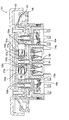
この発明の第1実施形態について、図1ないし図10を参照して説明する。ただし、図1はないし図4は押しボタンスイッチの異なる状態における切断正面図、図5は図1のA−A線矢視断面図、図6は作動体の回転量と作動体への荷重との関係図、図7、図9及び図10は第1実施形態にかかる押しボタンスイッチの結線図、図8は押しボタンの操作ストロークと操作荷重との関係図である。
【0051】
図1に示すように、本実施形態にかかる押しボタンスイッチ1は、平面視矩形状のスイッチケース3と、このスイッチケース3に押し込み可能に支持された押ボタン5と、スイッチケース3内に配設された補助接点としての常閉接点7及び2個のc接点9a,9bと、押ボタン5内に設けられ押ボタン5の押し込みに連動して各c接点9a,9bを開閉させる2つのスイッチング機構11a,11bとを備えている。
【0052】
スイッチケース3内には、その中央下部に常閉接点7が配設されるとともに、この常閉接点7を挟んでその両端部にc接点9a,9bそれぞれが配設されている。また、スイッチケース3外面の両側部にはフランジ13a,13bがそれぞれ形成されており、このフランジ13a,13bが例えばねじなどによりデータ入力用の教示ペンダント等に取り付けられる。
【0053】
常閉接点7は、スイッチケース3内で押ボタン5側(上方)に突出する可動部材15と、この可動部材15の下端部に導電性部材16を介して取り付けられた一対の可動端子17a,17bと、この可動端子17a,17bそれぞれに接離する一対の固定端子19a,19bとから構成されている。
【0054】
そして、可動部材15の下端部には可動部材15を上方へ付勢するコイルバネ21が取り付けられており、このコイルバネ21の付勢力により押ボタン5が押し込まれていない初期状態では可動端子17a,17bと固定端子19a,19bとが接触して閉状態となっている。また、スイッチケース3の下端部からは2本の金属製の端子片23a,23bが突出しており、これら端子片23a,23bは常閉接点7の固定端子19a,19bそれぞれと電気的に接続されている。
【0055】
各c接点9a,9bは、スイッチケース3内の両端部に形成された断面L字形の仕切壁25a,25bの下方にそれぞれ配設されている。そして、各c接点9a,9bは、その一端部27a,27bが他端部29a,29bを中心に回転可能に配設された可動端子31a,31bと、この可動端子31a,31bを挟んで上下方向に配設された常閉固定端子33a,33b及び常開固定端子35a,35bと、後述するスイッチング機構11a,11bの押圧片37a,37bによりその一端部39a,39bが押圧されるとその他端部41a,41bを中心に回転する作動体43a,43bと、両端が可動端子31a,31bの一端部27a,27b及び作動体43a,43bの一端部39a,39bに係止され可動端子31a,31bの一端部27a,27bを上方に付勢すると同時に作動体43a,43bの一端部39a,39bを上方に付勢するコイルバネ45a,45bとを備えたスナップアクション構造を構成している。
【0056】
ここで、各c接点9a,9bは、図1に示すように、押ボタン5が押し込まれていない初期状態では、可動端子31a,31bはコイルバネ45a,45bによって上方に付勢されて、常開固定端子35a,35bと離反するとともに常閉固定端子33a,33bと接触し、押しボタンスイッチ1は第1のOFF状態となっている。
【0057】
また、一方のc接点9aの可動端子31a、常閉固定端子33a及び常開固定端子35aは、スイッチケース3の下方から突出する3つの端子片46a,47a,48aとそれぞれ電気的に接続され、これと同様に、他方のc接点9bの可動端子31b、常閉固定端子33b及び常開固定端子35bは、スイッチケース3の下方から突出する3つの端子片46b,47b,48bとそれぞれ電気的に接続されている。
【0058】
ところで、押ボタン5には、上下方向に平面視矩形状の空間からなる収容部49が形成されており、この収容部49の中央には常閉接点7を押圧する押圧部材51が設けられている。また、この押圧部材51の右、左の両側には収容部49を上下方向に仕切る断面L字状の仕切板53a,53bがそれぞれ設けられている。そして、この仕切板53a,53bによって仕切られる収容部49の上部空間55a,55bには各c接点9a,9bを開閉させるスイッチング機構11a,11bが配設されている。
【0059】
また、この押ボタン5の両端部には、下方に突出する突出部57a,57bが設けられており、各突出部57a,57bにはコイルバネ59a,59bが外挿されている。そして、コイルバネ59a,59bの下端部はスイッチケース3底部の両端に固定されており、これら各コイルバネ59a,59bの付勢力により、押ボタン5は常時上方に付勢されている。
【0060】
スイッチング機構11a,11bは、c接点9a,9bの作動体43a,43bを押圧する押圧片37a,37bと、この押圧片37a,37bを押ボタン5の押し込みに連動して押し下げるスライドブロック61a,61bと、このスライドブロック61a,61bと係止する押圧軸63a,63bとから構成されている。
【0061】
押圧片37a,37bは、仕切板53a,53bと押圧部材51との間に形成された隙間部64a,64bから下方へ向かって配設され、その下端部がc接点9a,9bの作動体43a,43bの一端部に当接している。
【0062】
押圧軸63a,63bは、その内部が中空に形成され、押ボタン5内の上壁に取り付けられたコイルバネ65a,65bの下端部が押圧軸63a,63bの内部に固定され、押圧軸63a,63bがコイルバネ65a,65bにより下方へ付勢されている。
【0063】
また、この押圧軸63a,63bは、仕切板53a,53bに形成された貫通孔67a,67bに挿通されるとともに、押圧軸63a,63bの上端部のフランジ69a,69bが貫通孔67a,67b周縁の仕切板53a,53bに係止し、押圧軸63a,63bが下方へと移動(抜け)するのを規制している。さらに、押圧軸63a,63bのフランジ69a,69bの一方の側面には傾斜面71a,71bが形成されている。
【0064】
スライドブロック61a,61bは、その内部に上下方向に貫通する空間部73a,73bが形成されており、この空間部73a,73bに押圧軸63a,63bが挿通されている。また、このスライドブロック61a,61bは、仕切板53a,53bにより収容部49に形成される上部空間55a,55b内に水平方向(図1の左右方向)に移動自在に配置されており、スライドブロック61a,61bの一端部と仕切板53a,53bの側面との間にはスライドブロック61a,61bを押ボタン5の中央側へ付勢するコイルバネ75a,75bが配設されている。
【0065】
また、スライドブロック61a,61bの他端部77a,77bは、押圧片37a,37bの上端部に当接可能となっており、押ボタン5が押し込まれると、それに連動してスライドブロック61a,61bも下方に移動し、押圧片37a,37bを押し下げる。さらに、スライドブロック61a,61bの空間部73a,73bの一方の内壁には傾斜面79a,79bが形成され、この傾斜面79a,79bが押圧軸63a,63bのフランジ69a,69bの傾斜面71a,71bと係止している。
【0066】
また、図1及び図5に示すように、仕切板53a,53bと仕切壁25a,25bとの間にはU字形の分散部材81が設けられている。この分散部材81は、その上端部が仕切板53a,53bの下面に保持部材83a,83bを介して回転自在に保持される一方、その下端部81a,81bは仕切壁25a,25bの上面とその上方に設けられたガイド部材85a,85bとで形成される空間部87a,87bで水平方向(図1の前後方向)に摺動自在に保持されている。
【0067】
そして、図5(a)に示す初期状態から押ボタン5が押し込まれると、分散部材81はその下端部81a,81bが空間部87a,87b内を摺動しながら、その上端部を中心に同図中のα方向に回転し、完全に押し込まれた状態では、図5(b)に示すようになる。このような分散部材81が押しボタンスイッチ1内の両端部に設けられているため、押ボタン5のいずれの部分を押圧しても、分散部材81によりその押圧荷重を均等に分散して各c接点9a,9bを必ず同時に開閉させることができるようになっている。
【0068】
次に、上記のように構成された押しボタンスイッチ1の動作について図1ないし図4を参照しつつ説明する。
【0069】
図1に示す第1のOFF状態から押ボタン5を押し込むと、図2に示すように、両スイッチング機構11a,11bでは、スライドブロック61a,61bの傾斜面79a,79bと押圧軸63a,63bの傾斜面71a,71bとが係止した状態で、押圧軸63a,63bが押ボタン5とともに下方に移動する。また、この押ボタン5の押し込みにより、スライドブロック61a,61bの他端部77a,77bが押圧片37a,37bの上端部に当接して押圧片37a,37bが下方に押し下げられ、作動体43a,43bの一端部39a,39bがコイルバネ45a,45bに抗して下方に押圧される。
【0070】
このように、c接点9a,9bの作動体43a,43bが下方へ押圧されると、作動体43a,43bの一端部39a,39bが他端部41a,41bを中心に下方へと回転し、その回転に伴ってコイルバネ45a,45bが引き伸ばされていく。そして、作動体43a,43bの一端部39a,39bの回転量が、コイルバネ45a,45bによる可動端子31a,31bの一端部の付勢方向が上方から下方へと切り換わる第1デッドポイントに達すると、可動端子31a,31bはその他端部29a,29bを中心として下方へと回転し、常閉固定端子33a,33bから離反して常開固定端子35a,35bと接触する。こうして、押しボタンスイッチ1は第1のOFF状態からON状態に移行する。
【0071】
このとき、可動端子31a,31bはコイルバネ45a,45bによる付勢方向の切り換えによって常開固定端子35a,35b側に移動するためクリック感が発生し、操作者は押しボタンスイッチ1が第1のOFF状態からON状態へと移行したことを認識することができる。
【0072】
ここで、第1のOFF状態からON状態の間では、スライドブロック61a,61bの傾斜面79a,79bに対して、押圧軸63a,63bの傾斜面71a,71bによりスライドブロック61a,61bを押ボタン5の外方側へ押し遣ろうとする押圧力が作用するが、この押圧力よりも、スライドブロック61a,61bを押ボタン5の中心側へと突出させようとするコイルバネ75a,75bの付勢力の方が強いので、スライドブロック61a,61bが押ボタン5の端部側へと移動することはなく、押圧軸63a,63b及びスライドブロック61a,61bは、ともに押ボタン5と連動して下方へと移動する。
【0073】
ところで、このON状態から押ボタン5の押し込みを緩めると、押ボタン5の上方への移動に連動して押圧片37a,37bが上方に移動する。これにより、作動体43a,43bに対する押圧片37a,37bの押圧が解除され、作動体43a,43bの一端部39a,39bが上方へと回転する。
【0074】
そして、作動体43a,43bの一端部39a,39bの回転量が、コイルバネ45a,45bによる可動端子31a,31bへの付勢方向が下方から上方へと切り換わる第2デッドポイントに達すると、可動端子31a,31bはその他端部29a,29bを中心として上方へと回転し、常開固定端子35a,35bから離反して常閉固定端子33a,33bと接触する。こうして押しボタンスイッチ1はON状態から第1のOFF状態へと復帰する。
【0075】
ここで、このc接点9a,9bでは、上記した第1デッドポイントと第2デッドポイントとの関係が次のように設定されている。すなわち、図6に示すように、作動体43a,43bへの荷重が増大して第1デッドポイントに達する作動体43a,43bの一端部39a,39bの回転量は、作動体43a,43bへの荷重が減少されて第2デッドポイントに達する作動体43a,43bの一端部39a,39bの回転量より大きく設定されている。
【0076】
そのため、押しボタンスイッチ1がON状態から第1のOFF状態へと移行する押ボタン5の押込み量は、第1のOFF状態からON状態へと移行する押込み量よりも小さくなっている。従って、押ボタン5の押込み量の緩みが緩んだとしても、その緩みが所定範囲内、すなわち作動体43a,43bの回転量が第2デッドポイントに達するまでは、押しボタンスイッチ1はON状態に保持され、不意に第1のOFF状態へと移行するのが防止されている。
【0077】
続いて、図2に示すON状態から押ボタン5をさらに押し込むと、図3に示すように、押圧軸63a,63bの下端部が仕切壁(当接部)25a,25bの上面に当接する。そして、押ボタン5をさらに押し込むと押圧軸63a,63bが仕切壁25a,25bによって上方へと押し上げられ、押圧軸63a,63bのフランジ69a,69bと仕切板53a,53bの貫通孔67a,67b周縁との係合状態が解除される。
【0078】
このとき、押圧軸63a,63bの傾斜面71a,71bからスライドブロック61a,61bの傾斜面79a,79bに作用する押圧力が、コイルバネ75a,75bの付勢力より大きくなり、スライドブロック61a,61bの傾斜面79a,79bが押圧軸63a,63bの傾斜面71a,71bを摺接し、スライドブロック61a,61bが押ボタン5の外方へとスライドする。
【0079】
そして、このスライドブロック61a,61bの外方へのスライドに伴って、スライドブロック61a,61bの他端部77a,77bと押圧片37a,37bとの当接状態が解除され、押圧片37a,37bは上方へ移動可能になり、押圧片37a,37bによる作動体43a,43bへの押圧が解除される。このように、本実施形態のスイッチング機構11a,11bが本発明における解除手段を構成している。
【0080】
こうして、押圧片37a,37bによる作動体43a,43bへの押圧が解除されると、図4に示すように、作動体43a,43bの一端部39a,39bがコイルバネ45a,45bにより上方へ付勢されて回転し、作動体43a,43bの一端部39a,39bの回転によって、可動端子31a,31bの一端部の付勢方向が下方から上方へと切り換わって可動端子31a,31bの一端部が上方に回転し、常開固定端子35a,35bと接触していた可動端子31a,31bが常開固定端子35a,35bから離反して常閉固定端子33a,33bと接触する。その結果、押しボタンスイッチ1はON状態から第2のOFF状態に移行する。
【0081】
この第2のOFF状態では、図4に示すように、押ボタン5の押圧部材51は常閉接点7の可動部材15の上端部に当接して可動部材15を押し下げるため、常閉接点7の可動端子17a,17bと固定端子19a,19bとが強制的に開離される。その結果、例えば可動端子17a,17bと固定端子19a,19bとが溶着を起こしていた場合であっても、可動端子17a,17bと固定端子19a,19bとが強制的に離反されて常閉接点7は開状態になる。このように、押圧部材51と可動部材15とにより本発明における強制開離手段を構成している。
【0082】
次に、上記のように構成された押しボタンスイッチ1の回路結線の例を、図7を参照しつつ説明する。ここで、これらの図中におけるNC1及びNC2はc接点9a,9bの常閉固定端子33a,33bに相当し、NO1及びNO2は常開固定端子35a,35bに相当し、C1及びC2は可動端子31a,31bに相当し、接点NC3は常閉接点7の固定端子19a,19bに相当する。そして、第1回路及び第2回路はそれぞれc接点9a,9bにより構成されるが、詳細には、c接点9a,9bの常開固定端子35,35b(NO1,NO2)及び可動端子31a,31b(C1,C2)により第1、第2回路が構成される。
【0083】
図7(a)に示すように、この押しボタンスイッチ1の第1のOFF状態では、c接点9a,9bそれぞれにより構成される第1及び第2回路において、C1,C2がそれぞれNC1,NC2側に切り換わっているOFFの状態となっている。また、常閉接点7により構成される第3回路はNC1が閉じたONの状態となっている。
【0084】
続いて、押ボタン5が押し込まれると、図7(b)に示すように、第1及び第2回路においてC1,C2がそれぞれNO1,NO2側に切り換わってONになり、押しボタンスイッチ1はON状態となる。このとき、第3回路はNC3が閉じたONの状態が維持される。
【0085】
そして、押ボタン5がさらに押し込まれると、図7(c)に示すように、第1及び第2回路においてC1,C2がそれぞれNC1,NC2側に切り換わってOFFになり、押しボタンスイッチ1は第2のOFF状態となる。このとき、第3回路は強制開離手段によりNC3が開いてOFFの状態となる。
【0086】
このように、この押しボタンスイッチ1では、押ボタン5の押し込み操作により第1回路(9a)及び第2回路(9b)が同時にONまたはOFFし、第1のOFF状態、ON状態及び第2のOFF状態では、各回路が同一のON、OFF状態となるため、各回路をモニタしたときにON、OFF状態が相異する場合には、第1回路(9a)及び第2回路(9b)のうちいずれかが故障していると判断できる。
【0087】
ところで、この押しボタンスイッチ1の第1のOFF状態及び第2のOFF状態では、第1回路(9a)及び第2回路(9b)がともにOFFの状態となっているため、第1及び第2回路のON、OFF状態をモニタするだけでは、押しボタンスイッチ1のOFFが第1のOFF状態または第2のOFF状態のどちらであるのか判別することはできない。
【0088】
そこで、第3回路(7)の開閉状態は、第1のOFF状態と第2のOFF状態とで異なり、つまり、第3回路(7)が閉状態であれば、押しボタンスイッチ1が第1のOFF状態であり、第3回路(7)が開状態であれば、押しボタンスイッチ1が第2のOFF状態であることから、この第3回路(7)の開、閉状態をモニタすることにより、押しボタンスイッチ1の第1のOFF状態と第2のOFF状態とを判別することができる。
【0089】
次に、押しボタンスイッチ1を操作する際に押ボタン5に作用させる操作ストロークと操作荷重との関係について図8を用いて説明する。なお、同図中の丸数字はそれぞれ図番号に対応させている。
【0090】
図8に示すように、初期状態である第1のOFF状態からON状態となるまで、すなわち、図1に示す状態(丸数字「1」)から図2に示す状態(丸数字「2」)までは、押ボタン5の押し込みによる操作ストロークの増加とともに操作荷重が徐々に増加している。これは、押ボタン5の両端に配設されたコイルバネ59a,59bの付勢力によるものである。
【0091】
次に、第2図に示す状態(丸数字「2」)から第3図に示す状態(丸数字「3」)に移行するときは、押ボタン5の押し込みによる操作ストロークははとんど増加せず、操作荷重が急激に増加する。これは、スライドブロック61a,61bを水平移動させるのに大きな荷重を必要とするからである。
【0092】
続いて、第3図に示す状態(丸数字「3」)から第4図に示す状態(丸数字「4」)に移行するとき、操作荷重が急激に小さくなる。これは、押圧軸63a,63bとスライドブロック61a,61bとの係合が外れたためである。というのも、ON状態での操作時に操作者かパニックに陥って押ボタン5を強く押し込んだときには押ボタン5が軽くなった方が好ましいので、このように操作荷重を小さく設定することにより、ON状態から第2のOFF状態にスムーズに移行することができるようになる。
【0093】
次に、第4図に示す状態(丸数字「4」)よりも押ボタンを押し込むと、操作ストロークの増加とともに操作荷重が徐々に増加している。これは、押ボタン5の両端に配設されたコイルバネ59a,59b及び押圧軸63a,63bに配設されたコイルバネ65a,65bの付勢力によるものである。
【0094】
従って、上記した第1実施形態によれば、一つのケース2内に2個のc接点9a,9bを配設し、押ボタン5の押し込み操作により、これらの接点9a,9bを同時に開閉するため、例えば押しボタンスイッチ1の操作中に1個の接点が故障した場合であっても、もう1個の接点により押しボタンスイッチ1をON,OFFすることができ、押しボタンスイッチ1の信頼性を向上させることができる。ここで、c接点の数は2個に限定されるものではなく、3個以上設けても、同様の効果が得られるのは言うまでもない。
【0095】
また、c接点9a,9bがスナップアクション構造を有し、可動端子31a,31bが常開固定端子35a,35bに接触するときの押ボタン5の押込み量よりも小さい押込み量で可動端子31a,31bが常開固定端子35a,35bから離反するよう設定されているため、押しボタンスイッチ1がON状態であるときに押ボタン5の押し込みが緩んだとしても、その緩みが所定範囲内、すなわち作動体43a,43bの回転量が第2デッドポイントに達するまでは、押しボタンスイッチ1はON状態に保持され、操作者の意に反して不意に第1のOFF状態へと移行するのを防止することができる。
【0096】
しかも、c接点9a,9bがスナップアクション構造であるため、押しボタンスイッチ1が第1のOFF状態からON状態に移行する際、及びON状態から第2のOFF状態に移行する際に、適度なクリック感及び動作音が発生し、そのため操作者は押ボタン5を押し込んで押しボタンスイッチ1がON状態、すなわちデータ入力可能な状態であるか否かを容易に認識することができる。
【0097】
さらに、常閉接点7を設けたため、その開閉状態に基づいて押しボタンスイッチ1の第1のOFF状態第2のOFF状態とを判別することができる。このとき、常閉接点7は、上記したように、押しボタンスイッチ1の第2のOFF状態で開状態となる構成に限るものではなく、押しボタンスイッチ1がON状態のときに開状態になり、第2のOFF状態でも開状態を保持するように構成されていてもよい。
【0098】
また、上記した第1実施形態では、常閉接点7により構成される第3回路(図7参照)を独立して設けているが、図9に示すように、この常閉接点7を一方のc接点9a(9b)により構成される第2回路と直列に接続し、押しボタンスイッチ1を2回路により構成してもよい。
【0099】
このように構成した場合であっても、上記した実施形態と同様に常閉接点7の開閉状態をモニタすることにより第1のOFF状態と第2のOFF状態とを判別することができる。
【0100】
また、上記した第1実施形態では、c接点により構成される第1回路(9a)及び第2回路(9b)をともに常開固定端子35,35b(NO1,NO2)及び可動端子31a,31b(C1,C2)により構成しているが、図10に示すように、上記した図9における第2回路を、c接点9bの常閉固定端子33b(NC2)及び可動端子31b(C2)により構成し、押しボタンスイッチ1の3つのポジションで、第1回路側を第1のOFF、ON、第2のOFFの順に切り換わるようにする一方、第2回路側をこれとは逆に、ON、OFF、ONと切り換わるようにし、3つのポジションで、第1回路および第2回路のON、OFF状態が必ず逆になるように構成しても構わない。
【0101】
こうすれば、第1回路及び第2回路がともにONあるいはOFF状態となっているときは、いずれかの回路を構成するc接点9a,9bが故障であると容易に判断することができる。そして、この場合にはc接点9a,9bを相互にモニタすることで、相互の故障を判断できる。
【0102】
さらに、図10に示すような回路結線とした場合であっても、上記した第1実施形態と同様に、常閉接点7の開閉状態をモニタすることにより、押しボタンスイッチ1の第1のOFF状態と第2のOFF状態とを判別することができる。
【0103】
また、上記した第1実施形態では、常閉接点7を1個設けた場合について説明しているが、各c接点9a,9bそれぞれに対応して常閉接点を設けてもよく、こうすることにより、各c接点9a,9bのON、OFF状態を判別することができる。
【0104】
さらに、上記した第1実施形態では、押しボタンスイッチ1の第1のOFF状態と第2のOFF状態とを判別する手段である補助接点として常閉接点7を設けているが、例えば第1のOFF状態と第2のOFF状態とで開閉状態の切り換わる常開接点を設けてもよい。
【0105】
(第2実施形態)
この発明の第2実施形態について図11ないし図13を参照しつつ説明する。ただし、図11ないし図13はそれぞれ異なる状態における動作説明用の切断正面図である。なお、各図中、上記した第1実施形態と同一符号は同一または相当部分を示している。
【0106】
本実施形態において、c接点9a,9bの基本的な構成は、第1実施形態のものとほぼ同じであるため、以下では重複した説明は省略し、主として第1実施形態と相違する点について説明する。
【0107】
本実施形態における押しボタンスイッチ101では、図11に示すように、スイッチケース103、押ボタン105内に配設されたスイッチング機構107及び常閉接点109a,109bの構成が、第1実施形態と相違している。
【0108】
スイッチケース103内には、その中央下部に常閉接点109a,109bが2個配設されるとともに、これら常閉接点109a,109bを挟んでその両端部に上記した構成の一対のc接点9a,9bがそれぞれ配設されている。そして、スイッチケース103内壁には各c接点9a,9bの上部を覆うように仕切壁111a,111bが一体形成されている。
【0109】
常閉接点109a,109bそれぞれは、基本的に上記した第1実施形態における常閉接点7と同様に構成されている。すなわち、図11に示すように、一対の可動部材110a,110bと、可動部材110a,110bそれぞれに取り付けられた可動端子(図示省略)と、可動端子それぞれと接離する固定端子(図示省略)とにより、常閉接点109a,109bそれぞれが構成されている。
【0110】
また、各常閉接点109a,109bには、可動部材110a,110bを上方に付勢するコイルバネ112a,112bが設けられており、押ボタン105が押し込まれていない状態では、各常閉接点109a,109bは固定端子と可動端子とが接触して閉状態となっている。
【0111】
押ボタン105には、上下方向に平面視矩形状の空間からなる収容部113が形成されており、この収容部113内にc接点9a,9bを開閉動作させるスイッチング機構107が設けられている。
【0112】
このスイッチング機構107は、c接点9a,9bの作動体43a,43bを押圧する押圧片115a,115bと、この押圧片115a,115bを押ボタン105の押し込みに連動して押し下げる一対のスライドブロック117a,117bと、収容部113の上壁に取り付けられたコイルバネ119a,119bにより下方へと付勢される押圧軸121a,121bとから構成されている。
【0113】
押圧軸121a,121bは、押ボタン105の収容部113の上壁から下方へと延びる断面L字形の仕切板123a,123bと、収容部113の端部との間に配置されている。そして、押圧体121a,121bの内部は中空に形成されており、上記したコイルバネ119a,119bの下端部がその中空の底部に固定されている。
【0114】
また、スライドブロック117a,117bは押ボタン105内の中央部に接するようにして水平方向(図11の左右方向)に移動自在に配設され、スライドブロック117a,117bには、その内部に上下方向に貫通する空間部125a,125bが形成されるともとに、収容部113の上内面から垂下した垂下部127a,127bが空間部125a,125bを挿通して形成されている。
【0115】
そして、スライドブロック117a,117bの一端側下部には傾斜面129a,129bが形成されており、後述する押圧部材131の上端部の傾斜面と係合可能となっている。また、スライドブロック117a,117bの一端部の内壁と垂下部127a,127bとの間にはコイルバネ133a,133bが取り付けられており、スライドブロック117a,117bはこのコイルバネ133a,133bによって押ボタン105の中央側へ付勢されている。
【0116】
一方、垂下部127a,127bの下端は、仕切板123a,123bに形成された隙間部135a,135b内に入り込んで配置されており、さらにこの隙間部135a,135bの垂下部127a,127bとの間隙に押圧片115a,115bの上端部が挿通されて押圧片115a,115bが下方に向かって配設されている。
【0117】
また、押圧片115a,115bの上端部はスライドブロックの他端部137a,137bと当接可能となっており、押ボタン105が押し込まれてスライドブロック117a,117bがこの押ボタン105の押し込みに連動して下方へと移動すると、スライドブロック117a,117bの他端部137a,137bが押圧片115a,115bの上端部と当接して押圧片115a,115bを下方へと移動させる。
【0118】
さらに、仕切板123a,123bの中央寄り端部の下面には、断面凸形の突起部139a,139bが一体形成されており、スライドブロック117a,117bが下方へと移動すると、これに連動して下方へ移動し、常閉接点109a,109bの可動部材110a,110bに当接してこれを押し下げる。
【0119】
また、初期状態では、各スライドブロック117a,117bがコイルバネ133a,133bによって押ボタン105の中央側へと付勢されているため、スライドブロック117a,117b同士が接触した状態となっており、この状態で各スライドブロック117a,117bの傾斜面129a,129bが断面三角形状の凹部141を形成している。
【0120】
そして、この凹部141から所定距離だけ下方に上端部が嘴状の押圧部材131が設けられており、押ボタン105によりスライドブロック117a,117bが押し下げられると、この押圧部材131の上端部が、仕切板123a,123bの中央寄りの端部間に形成された空間に入り込んで凹部141に係合し、押ボタン105を押し込むに連れて、押圧部材131によりスライドブロック117a,117bが押し広げられるようになっている。
【0121】
次に、上記のように構成された押しボタンスイッチの動作について図11ないし図13を参照しつつ説明する。
【0122】
いま、図11に示す第1のOFF状態から押ボタン105を押し込むと、図12に示すように、スライドブロック117a,117bの他端部137a,137bが押圧片115a,115bの上端部に当接し、押圧片115a,115bが下方へ押し下げられる。
【0123】
そして、下方へと押し下げられた押圧片115a,115bにより、c接点9a,9bの作動体43a,43bの一端部39a,39bがコイルバネ45a,45bに抗して下方に押圧され、作動体43a,43bの一端部39a,39bが下方に回転し、その回転量が、コイルバネ45a,45bによる可動端子31a,31bの一端部の付勢方向が上方から下方へと切り換わる第1デッドポイントに達すると、図12に示すように、c接点9a,9bの可動端子31a,31bはその他端部29a,29bを中心として下方へと回転し、可動端子31a,31bが常閉固定端子33a,33bから離反して常開固定端子35a,35bと接触し、押しボタンスイッチ101は第1のOFF状態からON状態に移行する。
【0124】
このとき、押圧部材131の上端部は一対のスライドブロック117a,117bにより形成される凹部141と係合しており、この状態からさらに押ボタン105を押し込むと、図13に示すように、押圧部材131の上端部の傾斜面が各スライドブロック117a,117bの傾斜面129a,129bと摺接し、スライドブロック117a,117bが押ボタン105の外方へとスライドする。そして、スライドブロック117a,117bの他端部137a,137bも連動して押ボタン105の外方へスライドするため、スライドブロック117a,117bの他端部137a,137bと押圧片115a,115bとの当接状態が解除され、押圧片115a,115bは上方へ移動可能になり、押圧片115a,115bによる作動体43a,43bへの押圧が解除される。このように、本実施形態のスイッチング機構107が本発明における解除手段を構成している。
【0125】
そのため、押圧片115a,115bによる作動体43a,43bへの押圧が解除されると、図13に示すように、作動体43a,43bの一端部39a,39bがコイルバネ45a,45bにより上方へ付勢されて回転し、作動体43a,43bの一端部39a,39bの回転によって、可動端子31a,31bの一端部の付勢方向が下方から上方へと切り換わって可動端子31a,31bの一端部が上方に回転し、常開固定端子35a,35bと接触していた可動端子31a,31bが常開固定端子35a,35bから離反して常閉固定端子33a,33bと接触し、押しボタンスイッチ101はON状態から第2のOFF状態へと移行する。
【0126】
このとき、突起部139a,139bは常閉接点109a,109bの可動部材110a,110bをそれぞれ押し下げるため、常閉接点109a,109bそれぞれの可動端子は固定端子から離反して開状態となる。このとき、可動端子が固定端子に溶着していても、突起部139a,139bの押し下げによって強制的に開離される。
【0127】
なお、押しボタンスイッチ101がON状態から第1のOFF状態へと移行する押ボタン5の押込み量は、第1のOFF状態からON状態へと移行する押込み量よりも小さく設定され、押ボタン105の押込み量の緩みが緩んでも、その緩みが所定範囲内、すなわち作動体43a,43bの回転量が第2デッドポイントに達するまでは押しボタンスイッチ101はON状態に保持され、第1のOFF状態への不意の移行が防止されている点、並びにクリック感や動作音が得られる点は、上記した第1実施形態と同じである。
【0128】
従って、第2実施形態によれば、上記した第1実施形態と同等の効果を得ることができるのは勿論のこと、ひとつの押圧部材131によりスライドブロック117a,117bを水平移動させて押圧片115a,115bによる作動体43a,43bの押し込みを解除するため、構成が簡単となり、押しボタンスイッチ101のコストを低減することができる。
【0129】
また、上記した第2実施形態では、常閉接点109a,109bを2個設けているため、これら常閉接点109a,109bの開閉状態をモニタすることで、各c接点9a,9bが第1のOFF状態であるか、第2のOFF状態であるかを判別することができる。
【0130】
また、上記した第2実施形態において、c接点9a,9bによる第1及び第2回路を、第1実施形態で示した図7または図10と同様の結線構成にしてもよく、常閉接点109a,109bそれぞれをc接点9a,9bによる第1及び第2回路と直列に接続した回路構成にしてもよい。
【0131】
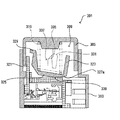
(第3実施形態)
この発明の第3実施形態について図14ないし図17を参照しつつ説明する。ただし、図14ないし図17はそれぞれ異なる状態における動作説明用の切断正面図である。なお、各図中、上記した第1実施形態と同一符号は同一または相当部分を示している。
【0132】
本実施形態において、c接点9a,9bの基本的な構成は、第1実施形態のものとほぼ同じであるため、以下では重複した説明は省略し、主として第1実施形態と相違する点について説明する。
【0133】
本実施形態における押しボタンスイッチ151では、図14に示すように、スイッチケース152、押ボタン153内に配設されたスイッチング機構154及び常閉接点155a,155bの構成が、第1実施形態と相違している。また、本実施形態では、押ボタン153を覆うように、ゴムカバー156及び外付ボタン157が取り付けられている。
【0134】
スイッチケース152内には、その中央下部に2つの収容部160a,160bを形成する収容体161が設けられており、各収容部160a,160bに常閉接点155a,155bがそれぞれ配設されている。また、収容体161を挟んでその両端部には、上記した構成の一対のc接点9a,9bがそれぞれ配設されている。さらに、スイッチケース152内壁には、第1実施形態と同様に、各c接点9a,9bの上部を覆うように断面L字形の仕切壁162a,162bが一体形成されている。
【0135】
各常閉接点155a,155bそれぞれは、基本的に上記した第1実施形態における常閉接点7と同様に構成されている。すなわち、図14に示すように、収容体161の上面に形成された貫通孔163a,163bから突出する可動部材164a,164bと、この可動部材164a,164bの下端部に導電性部材165a,165bを介して取り付けられた一対の可動端子166a,166bと、この可動端子166a,166bそれぞれに接離する一対の固定端子167a,167bとから構成されている。
【0136】
そして、可動部材164a,164bの下端部には可動部材164a,164bを上方へ付勢するコイルバネ168a,168bがそれぞれ取り付けられており、このコイルバネ168a,168bの付勢力により押ボタン153が押し込まれていない状態では、各常閉接点155a,155bは固定端子167a,167bと可動端子166a,166bとが接触して閉状態になっている。
【0137】
押ボタン153には、上下方向に平面視矩形状の空間からなる収容部170が形成されており、この収容部170の中央には二対の垂下部材171a,171b,172a,172bにより収容部170の上内面に固定される押圧板173が設けられており、この押圧板173と収容部170の上内面とで形成される上部空間174にc接点9a,9bを開閉動作させるスイッチング機構154が設けられている。また、押ボタン153の両端部には、後述する外付ボタン157及びゴムカバー156を取り付けるためのネジ穴175a,175bが形成されている。
【0138】
スイッチング機構154は、c接点9a,9bの作動体43a,43bを押圧する押圧片176a,176bと、この押圧片176a,176bを押ボタン153の押し込みに連動して押し下げる一対のスライドブロック177a,177bと、このスライドブロック177a,177bと係止する押圧軸180と、収容部170の上内面に取り付けられたコイルバネ181a,181bにより下方へと付勢される一対の押圧体182a,182bとから構成されている。
【0139】
押圧片176a,176bは、押圧板173の両端に形成された貫通孔183a,183bから下方へ向かって配設され、その下端部がc接点9a,9bの作動体43a,43bの一端部39a,39bに当接している。
【0140】
押圧軸180は、その内部が中空に形成され、収容部170の上内面に取り付けられたコイルバネ184の下端部が押圧軸180の内部に固定され、押圧軸180がコイルバネ184により下方へと付勢されている。
【0141】
また、この押圧軸180は、押圧板173の中央に形成された貫通孔185に挿通されるとともに、押圧軸180の上端部に形成された一対のフランジ186a,186bが貫通孔185周縁の押圧板173に係止し、押圧軸180が下方へと移動(抜け)するのを規制している。さらに、押圧軸180のフランジ186a,186bの側面には傾斜面187a,187bがそれぞれ形成されている。
【0142】
スライドブロック177a,177bは、その内部に上下方向に貫通する空間部178a,178bが形成されており、この空間部178a,178bに押ボタン153の中央側に配置される垂下部材171a,171bが挿通されている。また、このスライドブロック177a,177bは、上部空間174内に水平方向(図14の左右方向)に移動自在に配置されており、スライドブロック177a,177bの一端部190a,190bと空間部178a,178bに挿通される垂下部材171a,171bとの間に配設されたコイルバネ191a,191bにより押ボタン153の中央側へと付勢されている。
【0143】
さらに、スライドブロック177a,177bの一端部190a,190bには傾斜面192a,192bが形成されており、この傾斜面192a,192bが押圧軸180のフランジ186a,186bの傾斜面187a,187bと係止している。
【0144】
また、スライドブロック177a,177bの他端部193a,193bは、押圧片176a,176bの上端部に当接可能となっており、押ボタン153が押し込まれると、それに連動してスライドブロック177a,177bも下方に移動し、押圧片176a,176bを押し下げる。
【0145】
押圧体182a,182bは、収容部170両端の上内面から下方へと延びる断面L字形の仕切板194a,194bと、押圧板173の側面との間に配設されている。そして、押圧体182a,182bの内部は中空に形成されており、上記したコイルバネ181a,181bの下端部がその中空の底部に固定されている。
【0146】
さらに、押ボタン153の上面には、図14に示すように、ゴムカバー156を介して外付ボタン157が取り付けられており、押ボタン153上面の両端部にネジ止めされている。こうすることで、押ボタン153が直接押し込まれないため、押ボタン153の上面が変形したり破損したりするのを防止することができる。ここで、ゴムカバー156は押ボタン153の上面を覆うとともに、その両端部が、スイッチケース152側部のフランジ下面196a,196b側に固定されている。このようにして、押しボタンスイッチ151の防水性を高めている。
【0147】
次に、上記のように構成された押しボタンスイッチ151の動作について図14ないし17を参照しつつ説明する。
【0148】
いま、図14に示す第1のOFF状態から押ボタン153を押し込むと、図15に示すように、スライドブロック177a,177bの他端部193a,193bが押圧片176a,176bの上端部に当接し、押圧片176a,176bが下方へと押し下げられる。
【0149】
そして、下方へと押し下げられた押圧片176a,176bにより、c接点9a,9bの作動体43a,43bの一端部39a,39bがコイルバネ45a,45bに抗して下方に押圧され、作動体43a,43bの一端部39a,39bが下方に回転し、その回転量が、コイルバネ45a,45bによる可動端子31a,31bの一端部の付勢方向が上方から下方へと切り換わる第1デッドポイントに達すると、図15に示すように、c接点9a,9bの可動端子31a,31bはその他端部29a,29bを中心として下方へと回転し、可動端子31a,31bが常閉固定端子33a,33bから離反して常開固定端子35a,35bと接触し、押しボタンスイッチ151は第1のOFF状態からON状態に移行する。
【0150】
ここで、第1のOFF状態からON状態の間では、スライドブロック177a,177bの傾斜面192a,192bに対して、押圧軸180の傾斜面187a,187bによりスライドブロック177a,177bを押ボタン153の外方側へ押し遣ろうとする押圧力が作用するが、この押圧力よりも、スライドブロック177a,177bを押ボタン153の中心側へと押すコイルバネ191a,191bの付勢力の方が強いので、スライドブロック177a,177bが押ボタン153の端部側へと移動することはなく、押圧軸180及びスライドブロック177a,177bは、ともに押ボタン153と連動して下方へと移動する。
【0151】
このとき、押圧体182a,182bの下面は仕切壁162a,162bの上面に当接しているため、この状態から押ボタン153をさらに押し込むには、コイルバネ181a,181bの付勢力に抗する必要がある。こうすることで、ON状態からさらに押ボタン153を押し込むための荷重を大きくしている。
【0152】
続いて、図15に示すON状態から押ボタン153をさらに押し込むと、図16に示すように、押圧軸180の下端部が収容体161の上面に当接する。そして、押ボタン153をさらに押し込むと押圧軸180が収容体161によって上方へと押し上げられ、押圧軸180のフランジ186a,186bと押圧板173の貫通孔185の周縁との係合状態が解除される。
【0153】
このとき、押圧軸180の傾斜面187a,187bからスライドブロック177a,177bの傾斜面192a,192bに作用する押圧力が、コイルバネ191a,191bの付勢力より大きくなり、スライドブロック177a,177bの傾斜面192a,192bが押圧軸180の傾斜面187a,187bを摺接し、スライドブロック177a,177bが押ボタン153の外方へとスライドする。
【0154】
そして、このスライドブロック177a,177bの外方へのスライドに伴って、スライドブロック177a,177bの他端部193a,193bと押圧片176a,176bとの当接状態が解除され、押圧片176a,176bは上方へ移動可能になり、押圧片176a,176bによる作動体43a,43bへの押圧が解除される。このように、本実施形態のスイッチング機構154が本発明における解除手段を構成している。
【0155】
こうして、押圧片176a,176bによる作動体43a,43bへの押圧が解除されると、図17に示すように、作動体43a,43bの一端部39a,39bがコイルバネ45a,45bにより上方へ付勢されて回転し、作動体43a,43bの一端部39a,39bの回転によって、可動端子31a,31bの一端部の付勢方向が下方から上方へと切り換わって可動端子31a,31bの一端部が上方に回転し、常開固定端子35a,35bと接触していた可動端子31a,31bが常開固定端子35a,35bから離反して常閉固定端子33a,33bと接触する。その結果、押しボタンスイッチ151はON状態から第2のOFF状態に移行する。
【0156】
この第2のOFF状態では、図17に示すように、押ボタン153の押圧板173は常閉接点155a,155bの可動部材164a,164bの上端部に当接して可動部材164a,164bを押し下げるため、各常閉接点155a,155bの可動端子166a,166bと固定端子167a,167bとが強制的に開離される。その結果、例えば可動端子166a,166bと固定端子167a,167bとが溶着していた場合であっても、可動端子166a,166bと固定端子167a,167bとが強制的に離反されて常閉接点155a,155bは開状態になる。このように、押圧板173と可動部材164a,164bとにより本発明における強制開離手段を構成している。
【0157】
従って、第3実施形態によれば、上記した第1実施形態と同等の効果を得ることができるのは勿論のこと、ひとつの押圧軸180により一対のスライドブロック177a,177bを同時に水平移動させて、押圧片176a,176bによる作動体43a,43bの押し込みを解除できるため、構成が簡単となり、押しボタンスイッチ151のコストを低減することができる。
【0158】
また、上記した第3実施形態では、常閉接点155a,155bを2個設けているため、これら常閉接点155a,155bの開閉状態をモニタすることで、各c接点9a,9bが第1のOFF状態であるか、第2のOFF状態であるかを判別することができる。
【0159】
また、上記した第3実施形態において、c接点9a,9bによる第1及び第2回路を、第1実施形態で示した図7または図10と同様の結線構成にしてもよく、常閉接点155a,155bそれぞれをc接点9a,9bによる第1及び第2回路と直列に接続した回路構成にしてもよい。
【0160】
(第4実施形態)
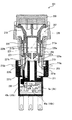
この発明の第4実施形態について図18ないし図21を参照しつつ説明する。ただし、図18ないし図21はそれぞれ異なる状態における動作説明用の切断正面図である。なお、各図中、上記した第1実施形態と同一符号は同一または相当部分を示している。
【0161】
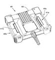
図18に示すように、本実施形態にかかる押しボタンスイッチ201は、第1実施形態と同一構成のc接点9a,9bが2個配設されたスイッチケース203と、このスイッチケース203の上端部に取り付けられた円筒状のケース部材205と、このケース部材205内に収容され、c接点9a,9bを開閉させる操作軸207と、この操作軸207の上端部に取り付けられる押ボタン209とから構成されている。
【0162】
スイッチケース203には、その下部に前後に2個のc接点9a,9bが並設されるとともに、これらc接点9a,9bの上部を覆うように、円筒状の係合部材211が設けられている。また、この係合部材211上端の内壁面にはテーパ213が形成されている。さらに、スイッチケース203の外側部には一対のフランジ215a,215bが形成されており、このフランジ215a,215bが例えばねじなどにより教示ペンダント等に固定される。
【0163】
ケース部材205内に配置される操作軸207は、対向配置される一対の押圧部材217a,217bと、これら押圧部材217a,217bの上端部に取り付けられ押ボタン209と押圧部材217a,217bとを連結する連結部材219とから構成されている。さらに、連結部材219の下部周面にはコイルバネ223が巻回され、連結部材219の周面中央部に形成された段部220、及びケース部材205の内周面の中央下寄りに形成された段部221に、コイルバネ223の両端部が係止されており、このコイルバネ223により押ボタン209、連結部材219及び押圧部材217a,217bが上方へ付勢されている。
【0164】
押圧部材217a,217bは、上下方向の板状の支持部225a,225bと、その下端に一体形成された係合片227a,227bとを備えている。この係合片227a,227bの下面には傾斜面229a,229bが形成されており、傾斜面229a,229bが上記した係合部材211の上端のテーパ213と係合可能に配設されている。
【0165】
また、各押圧部材217a,217bの係合片227a,227bの側部には下方へと延びる突出片231a,231bが形成されており、左側の押圧部材217bの突出片231bは右側よりも長く形成されている。そして、この長い突出片231bの下方には、2個のc接点9a,9bの作動体43a,43bを押圧する押圧片233が配置されており、この突出片231bが押圧片233の上端部に当接して押圧片233を押し下げることにより、作動体43a,43bが押圧され、c接点9a,9bが作動する。
【0166】
さらに、各押圧部材217a,217bの対向する支持部225a,225bの下部間にはコイルバネ235が配設されており、このコイルバネ235によって各押圧部材217a,217bが外方へと付勢されている。
【0167】
次に、上記のように構成された押しボタンスイッチ201の動作について図18ないし図21を参照しつつ説明する。
【0168】
いま、図18に示す第1のOFF状態から押ボタン209を押し込むと、図19に示すように、押ボタン209に連動して操作軸207が押し込まれ、長い突出片231bにより押圧片233が押し下げられる。これによって、押圧片233により、各c接点9a,9bの作動体43a,43bの一端部39a,39bがコイルばね45a,45bに抗して押圧され、作動体43a,43bの一端部39a,39bが下方に回転する。
【0169】
そして、作動体43a,43bの一端部39a,39bの回転量が、コイルバネ45a,45bによる可動端子31a,31bの一端部の付勢方向が上方から下方へと切り換わる第1デッドポイントに達すると、図19に示すように、c接点9a,9bの可動端子31a,31bはその他端部29a,29bを中心として下方へと回転し、可動端子31a,31bが常閉固定端子33a,33bから離反して常開固定端子35a,35bと接触する。その結果、押しボタンスイッチ201は第1のOFF状態からON状態に移行する。
【0170】
この状態から、押しボタンスイッチ201をさらに押し込むと、図20に示すように、押圧部材217a,217bの係合片227a,227bが係合部材211の中空部分に入り込み、係合片227a,227bの傾斜面229a,229bと係合部材211のテーパ213とが摺接しつつ、押圧部材217a,217bの突出片231a,231bが、コイルバネ235に抗して押しボタンスイッチ201の中心側へと移動する。
【0171】
これによって、長い突出片231bと押圧片233との当接状態が解除され、押圧片233は上方へ移動可能になり、押圧片233による作動体43a,43bへの押圧が解除される。このように、本実施形態では押圧部材217a,217bと係合部材211と押圧片233とにより、本発明の解除手段が構成されている。
【0172】
そして、押圧片233による作動体43a,43bへの押圧が解除されると、図21に示すように、作動体43a,43bの一端部39a,39bがコイルバネ45a,45bにより上方へ付勢されて回転し、作動体43a,43bの一端部39a,39bの回転によって、可動端子31a,31bの一端部の付勢方向が下方から上方へと切り換わって可動端子31a,31bの一端部が上方に回転し、常開固定端子35a,35bと接触していた可動端子31a,31bが常開固定端子35a,35bから離反して常閉固定端子33a,33bと接触し、押しボタンスイッチ201はON状態から第2のOFF状態へと移行する。
【0173】
従って、第4実施形態によれば、上記した第1実施形態と同等の効果を得ることができるのは勿論のこと、ひとつの押圧部材217bにより押圧片233の押し込み及び解除を行っているため、簡単な構成で押しボタンスイッチ201のON、OFF状態を切り換えることができ、押しボタンスイッチ201のコストを低減することができる。
【0174】
また、図18ないし図21には常閉接点(或いは常開接点)は図示されていないが、これをケース205内に設けてもよいのは勿論である。このとき、常閉接点(或いは常開接点)は1個であってもよく、c接点9a,9bそれぞれに対応して常閉接点(或いは常開接点)を設けてもよい。
【0175】
また、上記した第4実施形態においても、c接点9a,9bによる第1及び第2回路を、第1実施形態で示した図7または図10と同様の結線構成にしてもよく、常閉接点をc接点9a,9bによる第1及び第2回路と直列に接続した回路構成にしてもよい。
【0176】
(第5実施形態)
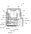
この発明の第5実施形態について図22ないし図25を参照しつつ説明する。ただし、図22ないし図25はそれぞれ異なる状態における動作説明用の切断正面図である。なお、各図中、前記第1実施形態と同一符号は同一または相当部分を示している。
【0177】
図22に示すように、本実施形態にかかる押しボタンスイッチ301は、スイッチケース303と、このスイッチケース303に押し込み可能に支持される押ボタン305と、スイッチケース303内に配設され第1実施形態と同一構成のc接点9a,9bと、スイッチケース303内に配設された第2実施形態と同一構成の常閉接点(図示省略)と、押ボタン305内に配設されc接点9a,9bを開閉させるスイッチング機構309とから構成されている。
【0178】
スイッチケース303は、図22に示すように、その下部が仕切板311によって2つの収容部313,315に仕切られており、左側の収容部313には前後に2個のc接点9a,9bが並設されるとともに、右側の収容部315には図示を省略する常閉接点が配設されている。
【0179】
また、押ボタン305の内部には、平面視矩形状の収容部317が形成されており、この収容部317内にスイッチング機構309が設けられている。このスイッチング機構309は、各c接点9a,9bの作動体43a,43bの一端部39a,39bを押圧する押圧片321と、この押圧片321を下方へと押し下げる押圧部材323とから構成されている。
【0180】
押圧部材323は、上面が開口した箱状に形成され、収容部317の上壁に取り付けられたコイルバネ319の下端がその内部空間の底部に係止されており、このコイルバネ319によって押圧片321は下方へ付勢されている。また、押圧部材323の底面を成す水平部325の下面両端には、それぞれ一対の傾斜面327a,327bが形成されている。
【0181】
さらに、押圧部材323の左側上端には突出片329が一体形成され、押ボタン305が押し込まれていない状態では、この突出片329と押圧片321の上端部とが係合するよう配置されている。一方、押ボタン305が押し込まれると、これに連動して押圧部材323が下方へ移動し、突出片329が押圧片321に当接してこれにより押圧片321が押し下げられる。
【0182】
また、図22中に破線で示すように、押圧部材323の外側前面には上端に円弧部331を有する係止片333が形成され、この係止片333の円弧部331が、押ボタン305の前面内壁に形成された左下方へ傾斜する傾斜面335を備えた段部337に係止している。
【0183】
次に、上記のように構成された押しボタンスイッチの動作について図22ないし図25を参照しつつ説明する。
【0184】
いま、図22に示す第1のOFF状態から押ボタン305を押し込むと、図23に示すように、押ボタン305に連動してコイルバネ319によって下方に付勢された押圧部材323が下方に移動し、この押圧部材323の移動と連動して押圧部材323の突出片329により押圧片321が押し下げられる。これによって、押圧片321により、各c接点9a,9bの作動体43a,43bの一端部39a,39bがコイルばね45a,45bに抗して下方に押圧され、作動体43a,43bの一端部39a,39bが下方に回転する。
【0185】
そして、作動体43a,43bの一端部39a,39bの回転量が、コイルバネ45a,45bによる可動端子31a,31bの一端部の付勢方向が上方から下方へと切り換わる第1デッドポイントに達すると、図23に示すように、c接点9a,9bの可動端子31a,31bはその他端部29a,29bを中心として下方へと回転し、可動端子31a,31bが常閉固定端子33a,33bから離反して常開固定端子35a,35bと接触する。その結果、押しボタンスイッチ201は第1のOFF状態からON状態に移行する。
【0186】
このとき、押圧部材323の底面の水平部325は仕切板311の上面に当接しており、この状態で押ボタン305をさらに押し込むと、図24に示すように、押圧部材323の係止片333の円弧部331が押ボタン305の内壁面に形成された段部337の傾斜面335を摺動し、この摺動に伴って、押圧部材323は、その底面における水平部325と右側の傾斜面327aとの境界角部339を中心として、段部337の傾斜面335の方向、すなわち右方に回転する。その結果、押圧部材323の突出片329と押圧片321の上端との係止状態が解除され、押圧片321が上方へ移動可能となる。このように、本実施形態では、スイッチング機構309が本発明の解除手段を構成している。
【0187】
こうして、押圧片321による作動体43a,43bへの押圧が解除されると、図25に示すように、作動体43a,43bの一端部39a,39bがコイルバネ45a,45bにより上方へ付勢されて回転し、作動体43a,43bの一端部39a,39bの回転によって、可動端子31a,31bの一端部の付勢方向が下方から上方へと切り換わって可動端子31a,31bの一端部が上方に回転し、常開固定端子35a,35bと接触していた可動端子31a,31bが常開固定端子35a,35bから離反して常閉固定端子33a,33bと接触し、押しボタンスイッチ201はON状態から第2のOFF状態へと移行する。
【0188】
このとき、収容部315内の常閉接点(図示省略)は開状態となるため、常閉接点の開閉状態をモニタすることで、押しボタンスイッチ301の第1OFF状態と第2OFF状態とを判別することができる。
【0189】
従って、第5実施形態によれば、第1実施形態と同様の作用効果が得られるものは勿論のこと、スイッチング機構309が押圧片321と押圧部材323とからなる簡単な構成であるため、押しボタンスイッチ301のコストを低減することができる。
【0190】
(第6実施形態)
この発明の押しボタンスイッチを、操作装置である産業用マニピュレーティングロボットにおける教示ペンダントに適用した場合の第6実施形態について図26ないし図30を参照しつつ説明する。ただし、図26は本実施形態における教示ペンダントの正面図、図27はこの教示ペンダントを背面側から見たときの斜視図、図28ないし図30はこの教示ペンダントに配設された押しボタンスイッチの回路図である。
【0191】
操作装置である産業用マニピュレーティングロボットにおける教示ペンダント401はロボットの制御装置に接続される携帯用ユニットであり、例えば図26に示すように構成される。
【0192】
教示ペンダント401は、図26に示すように、ペンダント本体403の両端部が把持部405a,405bとして両手で把持されるようになっており、ペンダント本体403の中央部には、液晶ディスプレイ(以下、LCDと称する)407が配設され、操作者はこのLCD407の表示画面を見ながら、ペンダント本体403のLCD407の両側に複数個ずつ配列された操作キー409a,409bやその他の操作キーを両手の親指などで適宜操作することで、ロボットに対してプログラム等のデータを教示したり、或いはロボットを作動させることが可能になる。
【0193】
このとき、単に操作キー409a,409bを操作すればロボットに対する教示等が可能になるのではなく、図27に示すように、ペンダント本体403の各把持部405a,405bの裏面側に配設された押しボタンスイッチの操作部411a,411bを操作し、押しボタンスイッチをON状態にした上で操作キー409a,409bを操作しなければ、ロボットに対するプログラムの教示や、ロボットの作動を行うことができないようになっている。
【0194】
この操作部411a,411bは断面L字形に形成され、ペンダント本体403を把持する左手及び右手の指先で押し込み可能に構成されており、各操作部411a,411bの内側には左手用及び右手用の第1実施形態における押しボタンスイッチ(図示省略)がそれぞれ配設されている。そして、操作部411a,411bを押し込むことにより,左手用及び右手用押しボタンスイッチの押ボタンを押し込むことができ、押しボタンスイッチをON,OFFさせることができる。
【0195】
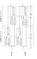
次に、上記した教示ペンダントの回路結線の例について図28を参照しつつ説明する。
【0196】
図28に示すように、この教示ペンダントは第1及び第2回路からなる2つの回路で構成されている。すなわち、第1回路では、右手用押しボタンスイッチの一方のc接点R1と左手用押しボタンスイッチの一方のc接点L1とが並列に接続されている。また、第2回路では、右手用押しボタンスイッチの他方のc接点R2と左手用押しボタンスイッチの他方のc接点L2とが並列に接続されるとともに、この並列回路に右手用押しボタンスイッチの常閉接点R3と左手用押しボタンスイッチの常閉接点L3とが直列に接続されている。
【0197】
このような回路結線により、この教示ペンダントでは、左手または右手のいずれかの手の操作によって第1回路および第2回路を導通させることにより、教示ペンダント401でのデータ入力を可能にしている。
【0198】
ここで、右手用及び左手用押しボタンスイッチには、上記した第1ないし第4実施形態における押しボタンスイッチが用いられ、NC1−R、NC2−Rは右手用押しボタンスイッチを構成するc接点R1,R2(例えば、図1のc接点9a,9bと同一)の常閉固定端子33a,33bに相当し、NO1−R、NO2−Rは右手用押しボタンスイッチを構成するc接点9a,9bの常開固定端子35a,35bに相当し、C1−R及びC2−Rは右手用押しボタンスイッチを構成するc接点R1,R2の可動端子31a,31bに相当する。
【0199】
同様に、NC1−L、NC2−Lは左手用押しボタンスイッチを構成するc接点L1,L2(例えば、図1のc接点9a,9bと同一)の常閉固定端子33a,33bに相当し、NO1−L、NO2−Lは左手用押しボタンスイッチを構成するc接点L1,L2の常開固定端子35a,35bに相当し、C1−L及びC2−Lは左手用押しボタンスイッチを構成するc接点L1,L2の可動端子31a,31bに相当する。また、R3及びL3は右手用及び左手用押しボタンスイッチを構成する常閉接点に相当する。
【0200】
次に、本実施形態における教示ペンダントの動作について図28ないし図30を参照しつつ説明する。いま、図28に示す操作部411a,411bが押し込まれていない状態から、例えば右手によって操作部411bが押し込まれると、図29に示すように、右手用押しボタンスイッチの2つのc接点R1,R2が同時に閉じて右手用押しボタンスイッチが第1のOFF状態からON状態に移行し、第1回路及び第2回路が導通する。
【0201】
これにより、教示ペンダント401は教示可能状態に移行し、ロボットへのプログラムの教示が可能となる。ここで、この教示ペンダント401では、右手または左手のいずれの手による操作でも教示ペンダント401を教示可能な状態とすることができるため、例えば右手で操作部411bを押し込んでプログラムを教示している際に、右手が疲れた場合であっても、ペンダント本体403を左手に持ち換えて、左手によって操作部411aを押し込むことにより教示ペンダント401を教示可能状態とすることができる。
【0202】
ところで、右手用操作部411bによって右手用押しボタンスイッチが押し込まれてON状態となっている状態から、さらに操作部411bが押し込まれると、図30に示すように、2つのc接点R1,R2がともに第2のOFF状態に移行するとともに、常閉接点R3が開いてOFFとなって、右手用押しボタンスイッチは第2のOFF状態となる。これにより、第1及び第2回路はともに導通が遮断され、教示ペンダント401はプログラムの教示が不可能な状態となる。
【0203】
このとき、第2回路では、右手用及び左手用押しボタンスイッチの常閉接点R3,L3は直列に接続されているため、左手用操作部411aにより左手用押しボタンスイッチを操作してON状態にした場合であっても、第2回路は導通せず左手用押しボタンスイッチの操作は無効となる。なお、この状態から教示ペンダント401を再度教示可能状態にするためには、右手を一旦操作部411bから離して、右手用押しボタンスイッチを第1のOFF状態に戻せばよい。
【0204】
従って、第6実施形態によれば、ペンダント本体403に右手用及び左手用の押しボタンスイッチを設け、これら押しボタンスイッチに配設された一方のc接点R1,L1それぞれと、他方のc接点R2,L2それぞれとを並列に接続したため、右手用または左手用のいずれか一方の操作で押しボタンスイッチをON状態にすることで、教示ペンダントを教示可能な状態とすることができる。
【0205】
その結果、例えば右手での操作中に右手が疲れた場合であっても、左手に持ち換えてプログラムの教示をすることができ、長時間の作業であっても、操作者にかかる負担を軽減して効率のよい教示作業を行うことができる。
【0206】
また、左手用及び右手用の押しボタンスイッチの常閉接点が直列に接続されているため、例えば一方の押しボタンスイッチが第2のOFF状態になっている場合には、第2回路の導通が遮断されるため、他方の押しボタンスイッチを操作しても教示ペンダントが教示可能状態になることを防止することができる。従って、非常時である第2のOFF状態におけるプログラム等の教示を防止することができる。
【0207】
また、上記した第6実施形態において、c接点による右手用押しボタンスイッチ及び左手用押しボタンスイッチの回路結線を、第1実施形態で示した図10と同様の結線、つまり第1回路側と第2回路側でON−OFF状態が逆に成るような結線にしてもよく、この場合も、上記した実施形態と同様の作用効果が得られることは言うまでもない。
【0208】
(第7実施形態)
この発明の押しボタンスイッチを、操作装置である産業用マニピュレーティングロボットにおける教示ペンダントに適用した第7実施形態について図31及び図32を参照しつつ説明する。ただし、図31は本実施形態における教示ペンダントの背面図、図32はこの教示ペンダントの動作説明図である。
【0209】
図31に示すように、この実施形態における教示ペンダント501の背面には、カバー部材503と、このカバー部材503によって覆われる第1実施形態で示した1個の押しボタンスイッチ1と、この押しボタンスイッチ1を押し込み操作可能な左手用及び右手用の操作レバー505a,505bが設けられている。
【0210】
押しボタンスイッチ1はカバー部材503に覆われてペンダント本体507の背面中央に配設されている。また、各操作レバー505a,505bは左右方向に移動自在に設けられており、その一端部には、左右方向に突出する複数の突出部509a,509bが所定間隔を置いて櫛状に形成されており、2つの操作レバー505a,505bは各突出部509a,509bが交互に噛合するように対向配置されている。また、各操作レバー505a,505bの他端部には、右手及び左手で把持される把持部511a,511bが設けられている。
【0211】
また、図32(a)は図31のA−A線矢視断面図であり、同図に示すように、各操作レバー505a,505bの突出部509a,509bの先端には、傾斜面513a,513bを有する係止片515a,515bがペンダント本体507内側に向けて一体形成されており、操作レバー505a,505bを水平方向に移動させることで、係止片515a,515bの表面が断面円弧状に加工された押ボタン5に当接して、押ボタン5が押し込み可能となっている。
【0212】
次に、本実施形態における教示ペンダントの操作について、図32を参照しつつ説明する。図32(a)に示す操作レバー505a,505bが操作されていない第1のOFF状態から、例えば左手によって操作レバー505aが同図のX方向に移動されると、同図(b)に示すように、左手用操作レバー505aの係止片515aが押ボタン5上を摺接し、押ボタン5が押し込まれる。
【0213】
これによって、押しボタンスイッチ1は、ON状態となり、教示ペンダント501ではプログラム等の教示が可能となる。このとき、右手用操作レバー505bによっても押ボタン5を押し込むことができるため、例えば左手が疲れた場合であっても、右手に持ち換えて、データ入力作業を続けることができる。
【0214】
続いて、同図(b)のON状態から左手用操作レバー505aをさらにX方向に引っ張ると、同図(c)に示すように、左手用操作レバー505aの係止片515aが押ボタン5を押し込みながら、押ボタン5上に乗り上げ、押しボタンスイッチ1が第2のOFF状態となる。
【0215】
その結果、教示ペンダント501では、プログラム等の教示ができない状態となる。このとき、同図に示すように、押ボタン5は左手用操作レバー505aによって完全に押し込まれているため、右手用操作レバー505bの係止片515bは押ボタン5を押し込むことができないようになっている。なお、この状態から教示ペンダント501を教示可能状態にするためには、各操作レバー505a,505bを同図(a)に示す初期位置に移動させた後、いずれかの操作レバー505a,505bにより押しボタンスイッチ1をON状態にすればよい。
【0216】
従って、第7実施形態によれば、第6実施形態と同等の効果が得られることは勿論、押しボタンスイッチ1が1個のみ設けられているため、回路構成が簡単になり、教示ペンダントのコストを低減することができる。
【0217】
また、押しボタンスイッチ1が1個のみ配設されているため、一旦、押しボタンスイッチ1が第2のOFF状態になれば、いずれの操作レバー505a,505bも初期位置に戻して、押しボタンスイッチ1を第1のOFF状態に復帰させない限り教示ペンダントにおける教示作業を行うことができないようになっている。従って、教示作業中における安全性を向上させることができる。
【0218】
また、上記した第7実施形態では、操作レバー505a,505bに形成された係止片515a,515bが押ボタン5上を摺接することにより押しボタンスイッチ1を押し込み操作するように構成しているが、これに限定されるものではなく、例えば、図33に示すように変形しても構わない。
【0219】
すなわち、同図に示すように、係止片515a,515bと押ボタン5との間に、中間部材517を押ボタン5の押し込み方向に移動自在に配設するとともに、押ボタン5をゴムカバー519で覆うように構成しても構わない。
【0220】
このような構成により、操作レバー505a,505bを操作すると、係止片515a,515bが中間部材517と摺接しつつ中間部材517をペンダント本体側507に移動させる。それに伴って、中間部材517がゴムカバー519を介して押ボタン5を押し込み、押しボタンスイッチ1がON、OFFする。
【0221】
従って、係止片515a,515bが中間部材517及びゴムカバー519を介して押ボタン5を押し込むため、係止片515a,515bと押ボタン5との摺接により押ボタン5が変形または破損するのを防止することができる。また、ゴムカバー519は防水手段としての役割も果たすが、ゴムカバー519を取り外し、中間部材517のみを配設して押ボタン5を押し込むようにしても同等の効果が得られる。
【0222】
なお、第7実施形態における押しボタンスイッチ1に代えて、上記した第2ないし第5実施形態における押しボタンスイッチを用いても構わない。
【0223】
さらに、第2ないし第5実施形態における押しボタンスイッチにおいて、c接点を3個以上設けてもよいのは勿論である。
【0224】
また、第1、第2,第4及び第5実施形態における押ボタンスイッチにおいて、第3実施形態に示したような外付ボタンを取り付けてもよいのは勿論である。
【0225】
また、上記した各実施形態における押しボタンスイッチにおいて、押ボタン部分を取り換え可能に構成してもよい。
【0226】
さらに、上記した各実施形態における押しボタンスイッチにおいて、第3実施例に示したようなゴムカバーにより防水構造を構成するほか、押ボタン部分にパッキングなどを介在させるなどにより、防水構造を施しておくことが望ましい。
【0227】
また、本発明は上記した実施形態に限定されるものではなく、その趣旨を逸脱しない限りにおいて上述したもの以外に種々の変更を行うことが可能である。
【0228】
【発明の効果】
以上のように、請求項1に記載の発明によれば、押しボタンスイッチのON,OFF状態を切り換える接点がケース内に2個以上設けられており、一つの押ボタンの押し込み操作により、各接点を同時にON,OFFすることができるため、例えば、1個の接点が故障した場合であっても、他の接点により押しボタンスイッチのON,OFF状態を切り換えることができ、押しボタンスイッチの信頼性を向上させることが可能になる。
【0229】
さらに、接点がいわゆるスナップアクション構造を有するため、押しボタンスイッチが第1のOFF状態からON状態に移行する際、及びON状態から第2のOFF状態に移行する際に、適度なクリック感及び動作音が発生し、操作者は押ボタン5を押し込んで押しボタンスイッチ1がON状態、すなわちデータ入力可能な状態であるか否かを容易に認識することが可能になり、信頼性の優れた押しボタンスイッチを提供することができる。
【0230】
また、スライドブロックと押圧軸との両傾斜面が、機械的摩耗などによって例えば押し込み方向に平行な向きに近づくように変化しても、スライドブロックに印加される力は横方向に印加されるコイルスプリングの付勢力のみであるため、押ボタンの操作荷重は変化せず、これによって使用者が感じる押ボタンの操作感は変わらず、一定の操作性を保つことができる。
【0231】
また、請求項2に記載の発明によれば、付勢手段に抗した作動体の一端部の回転量が第1デッドポイントに達すると、接点が第1のOFF状態からON状態に移行し、付勢手段による作動体の一端部の回転量が第2デッドポイントに達すると、ON状態から第2のOFF状態に移行するため、第1のOFF状態からON状態への移行およびON状態から第2のOFF状態への移行を確実に行うことができる。
【0232】
また、請求項3に記載の発明によれば、第2デッドポイントに達する作動体の一端部の回転量が、第1デッドポイントに達する作動体の一端部の回転量よりも小さく設定されているため、可動端子が常閉固定接点と接触する際の押ボタンの押込み量よりも小さい押込み量で可動端子が常閉固定端子から離反する。従って、押ボタンを押し込んで押しボタンスイッチをON状態にしている場合に、例えば、押ボタンを押し込む手が緩んだとしても、押し込みの緩みが所定範囲内、すなわち作動体の回転量が第2デッドポイントに達するまでは、可動端子が常閉固定端子から離反せず、押しボタンスイッチがON状態から不意に第1のOFF状態に移行するのを防止することが可能に成り、信頼性の優れた押しボタンスイッチを提供することができる。
【0233】
また、請求項4に記載の発明によれば、押しボタンスイッチが第1のOFF状態からON状態及び第2のOFF状態に移行する際に、一の接点と他の接点とが逆の開閉動作を行うため、一の接点と他の接点とが同じ開閉状態であることを検出することにより、いずれかの接点が故障していることを容易に判断することが可能になる。
【0234】
また、請求項5に記載の発明によれば、第1のOFF状態と第2のOFF状態とで開閉状態の異なる補助接点が設けられているため、この補助接点の開閉状態をモニタすることにより、押しボタンスイッチの第1のOFF状態と第2のOFF状態とを判別することが可能になる。
【0235】
また、請求項6に記載の発明によれば、各接点に補助接点が設けられているため、各接点が第1のOFF状態または第2のOFF状態のいずれの状態にあるかを判別することが可能になる。
【0236】
また、請求項7に記載の発明によれば、補助接点が溶着した場合であっても、強制開離手段により補助接点を開状態に移行することができ、押しボタンスイッチの第1のOFF状態と第2のOFF状態とを確実に判別することができる。
【0237】
また、請求項8に記載の発明によれば、押ボタンのどの部分を押圧しても、分散部材によってその押圧荷重を均等に分散させることができるため、各接点を必ず同時に開閉させることができる。
【0238】
また、請求項9に記載の発明によれば、ゴムカバーにより押ボタンを覆っているため、防水性を高めることができる。
【0239】
また、請求項10に記載の発明によれば、外付ボタンにより押ボタンを覆っているため、押ボタンの上面の変形や破損を防止することができる。
【0240】
また、請求項11に記載の発明によれば、左手用および右手用の操作部およびこれら操作部の把持により操作される押しボタンスイッチがそれぞれ配設されているため、いずれの手でもデータ入力作業を行うことができる。
【0241】
また、請求項12に記載の発明によれば、一方の押しボタンスイッチが第2のOFF状態に移行している場合には他方の操作部での押しボタンスイッチの操作が無効となるため、例えば、他方の押しボタンスイッチをON状態にするように操作した場合であってもデータの入力作業を不可能にすることができる。
【0242】
また、請求項13に記載の発明によれば、左手用および右手用の操作レバーを設け、いずれの操作レバーによっても押しボタンスイッチを操作することができるため、例えば、左手で操作中に当該左手が疲れた場合であっても、ペンダント本体を右手に持ち換えて、データ入力作業を行うことができる。
【0243】
さらに、この場合、ペンダント本体に設けるべき押しボタンスイッチは1個で済むため、教示ペンダントのコストを低減することができる。
【0244】
また、請求項14に記載の発明によれば、一方の操作レバーで押しボタンスイッチが第2のOFF状態に移行している場合には、他方の操作レバーによる操作が不能になるため、両方の操作レバーを操作して押しボタンスイッチを第1のOFF状態に復帰させない限り、教示ペンダントでのデータ入力作業を不可能にすることができる。
【図面の簡単な説明】
【図1】 この発明の第1実施形態における押しボタンスイッチのある状態の切断正面図である。
【図2】 この発明の第1実施形態における押しボタンスイッチの他の状態の切断正面図である。
【図3】 この発明の第1実施形態における押しボタンスイッチの異なる状態の切断正面図である。
【図4】 この発明の第1実施形態における押しボタンスイッチのさらに異なる状態の切断正面図である。
【図5】 図1のA−A線矢視断面図である。
【図6】 この発明の第1実施例における作動体の回転量と作動体への押圧荷重との関係図である。
【図7】 この発明の第1実施形態における回路結線図である。
【図8】 この発明の第1実施形態における操作ストロークと押ボタンの操作荷重との関係図である。
【図9】 この発明の第1実施形態における回路結線の変形例を示す図である。
【図10】 この発明の第1実施形態における回路結線の他の変形例を示す図である。
【図11】 この発明の第2実施形態における押しボタンスイッチのある状態の切断正面図である。
【図12】 この発明の第2実施形態における押しボタンスイッチの他の状態の切断正面図である。
【図13】 この発明の第2実施形態における押しボタンスイッチの異なる状態の切断正面図である。
【図14】 この発明の第3実施形態における押しボタンスイッチのある状態の切断正面図である。
【図15】 この発明の第3実施形態における押しボタンスイッチの他の状態の切断正面図である。
【図16】 この発明の第3実施形態における押しボタンスイッチの異なる状態の切断正面図である。
【図17】 この発明の第3実施形態における押しボタンスイッチのさらに異なる状態の切断正面図である。
【図18】 この発明の第4実施形態における押しボタンスイッチのある状態の切断正面図である。
【図19】 この発明の第4実施形態における押しボタンスイッチの他の状態の切断正面図である。
【図20】 この発明の第4実施形態における押しボタンスイッチの異なる状態の切断正面図である。
【図21】 この発明の第4実施形態における押しボタンスイッチのさらに異なる状態の切断正面図である。
【図22】 この発明の第5実施形態における押しボタンスイッチのある状態の切断正面図である。
【図23】 この発明の第5実施形態における押しボタンスイッチの他の状態の切断正面図である。
【図24】 この発明の第5実施形態における押しボタンスイッチの異なる状態の切断正面図である。
【図25】 この発明の第5実施形態における押しボタンスイッチのさらに異なる状態の切断正面図である。
【図26】 この発明の第6実施形態における教示ペンダントの正面図である。
【図27】 この発明の第6実施形態における教示ペンダントを背面側から見たときの斜視図である。
【図28】 この発明の第6実施形態の動作を説明する回路結線図である。
【図29】 この発明の第6実施形態の動作を説明する回路結線図である。
【図30】 この発明の第6実施形態の動作を説明する回路結線図である。
【図31】 この発明の第7実施形態における教示ペンダントの背面図である。
【図32】 この発明の第7実施形態における教示ペンダントの動作説明図である。
【図33】 この発明の第7実施形態における教示ペンダントの変形例である。
【図34】 従来の押しボタンスイッチを備えた教示ペンダントの斜視図である。
【図35】 従来の押しボタンスイッチの概略構成図である。
【図36】 従来の押しボタンスイッチの動作説明図である。
【図37】 従来の押しボタンスイッチの動作説明図である。
【図38】 従来の他の押しボタンスイッチの切断正面図である。
【図39】 図38の押しボタンスイッチの他の状態の切断正面図である。
【図40】 図38の押しボタンスイッチの異なる状態の切断正面図である。
【図41】 図38の押しボタンスイッチのさらに異なる状態の切断正面図である。
【符号の説明】
1,101,151,201,301 押しボタンスイッチ
3,103,152,203,303 スイッチケース
5,105,153,209,305 押ボタン
7,155a,155b 常閉接点(補助接点)
9a,9b c接点(接点)
11a,11b,107,154,309 スイッチング機構(解除手段)
15,164a,164b 可動部材(強制開離手段)
27a、27b 一端部
29a、29b 他端部
31a,31b 可動端子
33a,33b 常閉固定端子
35a,35b 常開固定端子
39a、39b 一端部
43a,43b 作動体
45a,45b コイルバネ(付勢部材)
51 押圧部材(強制開離手段)
81 分散部材
156 ゴムカバー
157 外付ボタン
173 押圧板(強制開離手段)
217a,217b 押圧部材(解除手段)
211 係合部材(解除手段)
233 押圧片(解除手段)
401,501 教示ペンダント
403,507 ペンダント本体
411a,411b 操作部
505a,505b 操作レバー[0001]
BACKGROUND OF THE INVENTION
The present invention relates to a push button switch that changes from a first OFF state to an ON state as the push button push amount increases, and shifts to a second OFF state when the push button is further pushed, and a teaching pendant including the push button switch.
[0002]
[Prior art]
For example, when performing manual operation on NC controlled machines such as robots, the operator often enters the danger area and performs work. In such a case, an accident during work due to contact with the machine may occur. In order to avoid this, a teaching pendant having a push button switch called a so-called enable switch (or deadman switch) is used.
[0003]
As shown in FIG. 34, this
[0004]
As a push button switch arranged in such a teaching pendant, for example, a push button switch called a snap action type as shown in FIG. 35 is used.
[0005]
As shown in the figure, the
[0006]
When the
[0007]
Next, when the
[0008]
The operator performs key input from the
[0009]
Further, when the operator feels a danger and panics and pushes the
[0010]
As described above, with this
[0011]
As such a push button switch having three positions, for example, a push button switch called a slow action type as shown in FIG. 38 can be used.
[0012]
The
[0013]
The
[0014]
The
[0015]
Each
[0016]
A lower portion of the
[0017]
When the
[0018]
When the
[0019]
[Problems to be solved by the invention]
By the way, since the conventional push button switches 602 and 701 described above have only one contact, for example, when this contact does not function due to a failure or the like during data input work, the push button switch There was a problem that the ON / OFF operation could not be performed and the switch could not function as an enable switch, resulting in lack of reliability.
[0020]
Further, in the slow action type
[0021]
Further, in the slow action type
[0022]
The present invention has been made in view of the above problems, and even when a single contact breaks down during use of the push button switch, the push button switch can be reliably turned on and off. An object is to provide a push button switch and a teaching pendant using the same.
[0023]
In addition, when the push button switch is in the ON state, the push button switch that can prevent the hand pushing the push button from loosening and the push button switch from unexpectedly shifting to the first OFF state is used, and this The purpose is to provide a teaching pendant.
[0024]
[Means for Solving the Problems]
In order to solve the above-described problems, a push button switch according to the present invention includes a switch case, a push button supported so as to be able to be pushed into the case, and one end portion that is rotatable around the other end portion in the case. A movable terminal arranged in the case, a contact made up of a normally open fixed terminal that is fixed in the case, and the movable terminal contacts and separates by rotation of one end thereof, and one end thereof can be rotated in conjunction with the pushing of the push button. And an end of the operating body at the same time as energizing the one end of the movable terminal by engaging the one end of the movable terminal and one end of the operating body. Urging means for urging in one direction, and release means for releasing the interlocking with the push button of the operating body by pushing the push button a predetermined amount or moreThe releasing means moves in the pressing direction in conjunction with the pressing of the push button and is slidable in a lateral direction perpendicular to the pressing direction, and is an inclined surface intersecting both the pressing direction and the lateral direction. Formed by a slide block, a coil spring that urges the slide block in a direction parallel to the lateral direction, and an inclined surface that engages with the inclined surface of the slide block. A pressure shaft that converts the force into the lateral force through the inclined surface and transmits the force to the slide block, and the pressure shaft fixed to the switch case. And a pressing piece interposed between an end of the slide block and one end of the operating body, and the end of the slide block and the pressing A piece is arranged side by side at one end of the actuating body in the moving direction by the pushing of the slide block,As you push the pushbutton,When the slide block moves in the push-in direction, the end of the slide block comes into contact with the pressing piece, and is pressed by the end and the pressing piece presses one end of the operating body, thereby One end is rotated against the biasing means, and this rotationThe movable terminal contacts the normally open fixed terminal and the contact is shifted from the first OFF state to the ON state;When the push button is further pushed, the pressing shaft comes into contact with the contact portion, and the force transmitted to the slide block via the inclined surface of the pressing shaft exceeds the urging force of the coil spring, the slide block Starts sliding in the lateral direction, further pushes the push button, and when the slide block is pushed more than the predetermined amount, the slide block slides in the lateral direction to bring the end of the slide block into contact with the pressing piece. Is released, the pressing of the one end of the operating body by the pressing piece is released,The rotation of one end of the operating body against the urging means is released.ThenThe movable terminal moves away from the normally open fixed terminal and shifts from the ON state to the second OFF state, and two or more of the contacts are provided in the case, and the push button is pushed in The contacts are turned on and off at the same time.
[0025]
According to such a configuration, two or more contacts for switching the ON / OFF state of the push button switch are provided in the case, and each contact can be turned ON / OFF simultaneously by pressing one push button. Therefore, for example, even when one contact fails, the ON / OFF state of the push button switch can be switched by another contact. Therefore, the reliability of the push button switch can be improved.Moreover, even if both inclined surfaces of the slide block and the pressing shaft change so as to approach, for example, a direction parallel to the pushing direction due to mechanical wear or the like, the force applied to the slide block is applied in the lateral direction. Since only the urging force of the spring is used, the operation load of the push button does not change, and the operation feeling of the push button felt by the user does not change, and a certain operability can be maintained.
[0026]
In the push button switch according to the present invention, the amount of rotation of the one end portion of the operating body against the urging means due to the pressing of the one end portion of the operating body of the pressing piece is the movable terminal by the urging means. When the first dead point for switching the biasing direction from one direction to the other direction is reached, the movable terminal comes into contact with the normally open fixed terminal, and the contact changes from the first OFF state to the ON state, The pressing of the one end portion of the operating body by the pressing piece is released, and the amount of rotation of the one end portion of the operating body by the biasing means changes the biasing direction of the movable terminal by the biasing means from one direction to the other direction. When the second dead point to be switched to is reached, the movable terminal moves away from the normally open fixed terminal and shifts from the ON state to the second OFF state.
[0027]
According to such a configuration, when the amount of rotation of the one end of the operating body against the biasing means reaches the first dead point, the contact point shifts from the first OFF state to the ON state, and the operating body by the biasing means. When the amount of rotation at one end of the first reaches the second dead point, the ON state shifts to the second OFF state, so the transition from the first OFF state to the ON state and from the ON state to the second OFF state. The transition can be made reliably.
[0028]
In addition, the push button switch according to the present invention includes an end portion of the operating body when the second dead point is reached in the transition from the ON state to the first OFF state by loosening the push button. Is set to be smaller than the rotation amount of one end of the operating body when the first dead point is reached.
[0029]
According to such a configuration, the rotation amount of the one end portion of the operating body that reaches the second dead point is set smaller than the rotation amount of the one end portion of the operating body that reaches the first dead point. The movable terminal is separated from the normally open fixed terminal with a pressing amount smaller than the pressing amount of the push button when contacting the normally open fixed terminal.
[0030]
Therefore, since it has a so-called hysteresis characteristic in which the amount of rotation at one end of the operating body is different between the case where the first OFF state is shifted to the ON state and the case where the ON state is shifted to the first OFF state. When the push button is pushed in and the push button switch is in the ON state, for example, even if the hand that pushes the push button is loosened, the looseness of the push is within a predetermined range, that is, the rotation amount of the operating body becomes the second dead point Until it reaches, the movable terminal does not move away from the normally open fixed terminal, and the push button switch can be prevented from unexpectedly shifting from the ON state to the first OFF state.
[0031]
In the push button switch according to the present invention, one of the contacts includes a normally closed fixed terminal, and the one contact is connected to the movable terminal when the other contacts are in a first OFF state. The normally closed fixed terminal is in contact with the other contact, and when the other contact is in the ON state, the movable terminal and the normally closed fixed terminal are in a separated state, and the other contact is in the second OFF state. At this time, the movable terminal and the normally closed fixed terminal are in contact with each other.
[0032]
According to such a configuration, when the push button switch shifts from the first OFF state to the ON state and the second OFF state, one contact and the other contact perform reverse opening / closing operations. When one of the contacts and the other contact indicate the same open / close state, it can be easily determined that one of the contacts has failed.
[0033]
Further, the push button switch according to the present invention has an auxiliary contact that is opened or closed when the respective contacts are in the first OFF state, and is closed or opened when the respective contacts are in the second OFF state. It is provided in the case.
[0034]
According to such a configuration, the auxiliary contacts having different opening / closing states are provided in the first OFF state and the second OFF state. Therefore, by monitoring the opening / closing state of the auxiliary contact, the push button switch The first OFF state and the second OFF state can be distinguished.
[0035]
That is, in the first OFF state and the second OFF state of the push button switch, since the movable terminal and the normally open fixed terminal of each contact are in the open state, the open / close state of the movable terminal and the normally open fixed terminal is monitored. However, it is not possible to determine whether the push button switch indicates the first OFF state or the second OFF state. However, by providing such an auxiliary contact, the first OFF state and the second OFF state of the push button switch are not provided. 2 can be discriminated.
[0036]
The push button switch according to the present invention is characterized in that the auxiliary contacts are provided corresponding to the respective contacts. According to such a configuration, since each contact is provided with an auxiliary contact, it is determined by monitoring the auxiliary contact whether each contact is in the first OFF state or the second OFF state. be able to.
[0037]
In the push button switch according to the present invention, the auxiliary contact is a normally closed contact that is closed when each of the contacts is in the first OFF state and is open when the second OFF state. And forcibly opening means for forcibly opening the auxiliary contact in the second OFF state.
[0038]
According to such a configuration, for example, even when the auxiliary contact is welded, the auxiliary contact can be shifted to the open state by the forcible separation means, and the first OFF state and the second state of the push button switch can be changed. An OFF state can be reliably determined.
[0039]
In addition, the push button switch according to the present invention is characterized in that it includes a dispersing member that evenly distributes the pressing load caused by pressing the push button. According to such a configuration, any portion of the push button can be pressed, and the pressing load can be evenly distributed by the dispersing member, so that a plurality of contacts can always be opened and closed simultaneously.
[0040]
The push button switch according to the present invention includes a rubber cover attached to cover the push button. According to such a configuration, since the push button is covered with the rubber cover, the waterproof property can be improved.
[0041]
The push button switch according to the present invention includes an external button attached so as to cover the push button. According to such a configuration, the external buttonPushSince the button is covered, deformation and breakage of the upper surface of the push button can be prevented.
[0042]
Further, the teaching pendant of the present invention includes a pendant main body, a left-hand and right-hand operation unit gripped by a left hand and a right hand, and the push button switch to be operated by gripping inside each of the operation units. And the push button switch on the inside thereof is shifted to the ON state by gripping one of the operation units, thereby enabling a data input operation.
[0043]
According to such a configuration, the left-hand and right-hand operation units and the push button switches operated by gripping these operation units are respectively provided, so that data input work can be performed with any hand. . For example, even if you are tired of your left hand when you are performing data entry operations with the push button switch turned on in the left hand operation part, you can change the pendant body with your right hand and use the right hand operation part. The push button switch can be turned on.
[0044]
Further, the teaching pendant of the present invention is configured such that when the push button switch inside thereof shifts to the second OFF state by gripping one of the operation parts, the inside push by gripping the other operation part. The feature is that the operation of the button switch is disabled.
[0045]
According to such a configuration, when one of the push button switches has shifted to the second OFF state, the operation of the push button switch in the other operation unit becomes invalid. For example, the other push button Even when the switch is operated to be in the ON state, the teaching pendant does not enter the teaching enable state, and data input work can be prevented from being performed.
[0046]
In addition, the teaching pendant of the present invention is provided with one push button switch on the pendant body, and is operated for the right hand and the left hand that can be pushed by the push button of the push button switch held by the right hand and the left hand. A lever is provided, and when the push button switch shifts to the ON state by one of the two operation levers, a data input operation is enabled.
[0047]
According to such a configuration, the left and right hand operating levers are provided, and the push button switch can be operated by either operating lever. For example, when the left hand is tired during operation with the left hand, Even if it exists, the pendant body can be changed to the right hand and data input work can be performed. In addition, since only one push button switch should be provided on the pendant body, the cost of the teaching pendant can be reduced.
[0048]
Further, the teaching pendant of the present invention makes it impossible to operate the push button switch by the other operation lever when the push button switch shifts to the second OFF state by gripping one operation lever. It is characterized by.
[0049]
According to such a configuration, when the push button switch is shifted to the second OFF state with one operation lever, the operation with the other operation lever becomes impossible. Unless the push button switch is returned to the first OFF state, data input can be disabled.
[0050]
DETAILED DESCRIPTION OF THE INVENTION
(First embodiment)
A first embodiment of the present invention will be described with reference to FIGS. However, FIG. 1 thru | or FIG. 4 is a cutting | disconnection front view in the state with a different pushbutton switch, FIG. 5 is AA arrow sectional drawing of FIG. 1, FIG. 6 is the rotation amount of a working body, and the load to a working body. FIG. 7, FIG. 9, and FIG. 10 are connection diagrams of the push button switch according to the first embodiment, and FIG. 8 is a relationship diagram of the operation stroke of the push button and the operation load.
[0051]
As shown in FIG. 1, a
[0052]
In the
[0053]
The normally
[0054]
A
[0055]
The
[0056]
Here, as shown in FIG. 1, in the initial state where the
[0057]
Further, the
[0058]
By the way, the
[0059]
Further, projecting
[0060]
The switching
[0061]
The
[0062]
The inside of the
[0063]
The
[0064]
The slide blocks 61a and 61b are formed therein with
[0065]
Further, the
[0066]
Further, as shown in FIGS. 1 and 5, a
[0067]
When the
[0068]
Next, the operation of the
[0069]
When the
[0070]
Thus, when the operating
[0071]
At this time, the
[0072]
Here, between the first OFF state and the ON state, the slide blocks 61a and 61b are pushed by the
[0073]
By the way, when the
[0074]
When the amount of rotation of the one
[0075]
Here, in the
[0076]
Therefore, the push amount of the
[0077]
Subsequently, when the
[0078]
At this time, the pressing force acting on the
[0079]
As the slide blocks 61a and 61b slide outward, the contact state between the
[0080]
When the pressing of the
[0081]
In this second OFF state, as shown in FIG. 4, the pressing
[0082]
Next, an example of circuit connection of the
[0083]
As shown in FIG. 7A, when the
[0084]
Subsequently, when the
[0085]
When the
[0086]
As described above, in the
[0087]
By the way, in the first OFF state and the second OFF state of the
[0088]
Therefore, the open / close state of the third circuit (7) is different between the first OFF state and the second OFF state, that is, if the third circuit (7) is in the closed state, the
[0089]
Next, the relationship between the operation stroke applied to the
[0090]
As shown in FIG. 8, from the first OFF state, which is the initial state, to the ON state, that is, the state shown in FIG.Round number “1”) To the state shown in FIG.Round number “2”), The operation load gradually increases as the operation stroke increases due to the
[0091]
Next, the state shown in FIG.Round number “2”) To the state shown in FIG.Round number “3”), The operation stroke due to the push-in of the
[0092]
Subsequently, the state shown in FIG.Round number “3”) To the state shown in FIG.Round number “4”), The operating load decreases rapidly. This is because the engagement between the
[0093]
Next, the state shown in FIG.Round number “4”When the push button is pushed in, the operation load gradually increases as the operation stroke increases. This is due to the urging forces of the
[0094]
Therefore, according to the first embodiment described above, two
[0095]
Further, the
[0096]
Moreover, since the
[0097]
Furthermore, since the normally
[0098]
In the first embodiment described above, the third circuit (see FIG. 7) constituted by the normally
[0099]
Even in this case, the first OFF state and the second OFF state can be determined by monitoring the open / close state of the normally
[0100]
Further, in the first embodiment described above, the first circuit (9a) and the second circuit (9b) configured by the c contacts are both the normally open fixed
[0101]
In this way, when both the first circuit and the second circuit are in the ON or OFF state, it is possible to easily determine that the
[0102]
Further, even in the case of the circuit connection as shown in FIG. 10, the first OFF of the
[0103]
In the first embodiment described above, the case where one normally
[0104]
Further, in the first embodiment described above, the normally
[0105]
(Second Embodiment)
A second embodiment of the present invention will be described with reference to FIGS. However, FIG. 11 to FIG. 13 are cut front views for explaining operations in different states. In each figure, the same reference numerals as those in the first embodiment indicate the same or corresponding parts.
[0106]
In the present embodiment, since the basic configuration of the
[0107]
In the
[0108]
In the
[0109]
Each of the normally closed
[0110]
The normally closed
[0111]
The
[0112]
The
[0113]
The
[0114]
Further, the slide blocks 117a and 117b are disposed so as to be movable in the horizontal direction (left and right direction in FIG. 11) so as to be in contact with the center portion in the
[0115]
In addition,
[0116]
On the other hand, the lower ends of the hanging
[0117]
Further, the upper end portions of the
[0118]
Further,
[0119]
In the initial state, the slide blocks 117a and 117b are biased toward the center of the
[0120]
A
[0121]
Next, the operation of the push button switch configured as described above will be described with reference to FIGS.
[0122]
Now, when the
[0123]
Then, by the
[0124]
At this time, the upper end portion of the
[0125]
Therefore, when the pressure on the operating
[0126]
At this time, since the
[0127]
Note that the push amount of the
[0128]
Therefore, according to the second embodiment, the same effect as that of the first embodiment described above can be obtained, and the slide blocks 117a and 117b are horizontally moved by the single pressing
[0129]
In the second embodiment described above, two normally closed
[0130]
In the second embodiment described above, the first and second circuits by the
[0131]
(Third embodiment)
A third embodiment of the present invention will be described with reference to FIGS. However, FIGS. 14 to 17 are cut front views for explaining the operation in different states. In each figure, the same reference numerals as those in the first embodiment indicate the same or corresponding parts.
[0132]
In the present embodiment, since the basic configuration of the
[0133]
In the
[0134]
In the
[0135]
Each of the normally closed
[0136]
[0137]
The
[0138]
The
[0139]
The
[0140]
The inside of the
[0141]
The
[0142]
The slide blocks 177a and 177b are formed therein with
[0143]
Further, inclined
[0144]
Further, the
[0145]
The
[0146]
Further, as shown in FIG. 14,
[0147]
Next, the operation of the
[0148]
Now, when the
[0149]
Then, by the
[0150]
Here, during the first OFF state to the ON state, the slide blocks 177a and 177b are pushed by the
[0151]
At this time, since the lower surfaces of the
[0152]
Subsequently, when the
[0153]
At this time, the pressing force acting on the
[0154]
As the slide blocks 177a and 177b slide outward, the contact state between the other ends 193a and 193b of the slide blocks 177a and 177b and the
[0155]
Thus, when the pressing of the
[0156]
In this second OFF state, as shown in FIG. 17, the
[0157]
Therefore, according to the third embodiment, the same effect as that of the first embodiment described above can be obtained, and the pair of
[0158]
Further, in the third embodiment described above, two normally closed
[0159]
In the third embodiment described above, the first and second circuits by the
[0160]
(Fourth embodiment)
A fourth embodiment of the present invention will be described with reference to FIGS. However, FIG. 18 thru | or FIG. 21 is the cutting | disconnection front view for operation | movement description in a respectively different state. In each figure, the same reference numerals as those in the first embodiment indicate the same or corresponding parts.
[0161]
As shown in FIG. 18, the
[0162]
The
[0163]
An
[0164]
The
[0165]
Further, projecting
[0166]
Further, a
[0167]
Next, the operation of the
[0168]
Now, when the
[0169]
When the amount of rotation of the one
[0170]
When the
[0171]
As a result, the contact state between the
[0172]
Then, when the pressure on the
[0173]
Therefore, according to the fourth embodiment, since the same effect as the first embodiment described above can be obtained, the
[0174]
18 to 21 do not show a normally closed contact (or a normally open contact), it is needless to say that this may be provided in the
[0175]
Also in the fourth embodiment described above, the first and second circuits by the
[0176]
(Fifth embodiment)
A fifth embodiment of the present invention will be described with reference to FIGS. However, FIGS. 22 to 25 are cut front views for explaining operations in different states. In each figure, the same reference numerals as those in the first embodiment denote the same or corresponding parts.
[0177]
As shown in FIG. 22, a
[0178]
As shown in FIG. 22, the lower portion of the
[0179]
In addition, a
[0180]
The pressing
[0181]
Further, a protruding
[0182]
Further, as shown by a broken line in FIG. 22, a
[0183]
Next, the operation of the push button switch configured as described above will be described with reference to FIGS.
[0184]
Now, when the
[0185]
When the amount of rotation of the one
[0186]
At this time, the
[0187]
When the pressing of the
[0188]
At this time, since the normally closed contact (not shown) in the
[0189]
Therefore, according to the fifth embodiment, the
[0190]
(Sixth embodiment)
A sixth embodiment in which the push button switch of the present invention is applied to a teaching pendant in an industrial manipulating robot as an operating device will be described with reference to FIGS. However, FIG. 26 is a front view of the teaching pendant in this embodiment, FIG. 27 is a perspective view of the teaching pendant when viewed from the back side, and FIGS. 28 to 30 are push button switches arranged on the teaching pendant. It is a circuit diagram.
[0191]
A
[0192]
As shown in FIG. 26, the
[0193]
At this time, if the
[0194]
The
[0195]
Next, an example of the circuit connection of the teaching pendant will be described with reference to FIG.
[0196]
As shown in FIG. 28, this teaching pendant is composed of two circuits including a first circuit and a second circuit. That is, in the first circuit, one c-contact R1 of the right-hand pushbutton switch and one c-contact L1 of the left-hand pushbutton switch are connected in parallel. In the second circuit, the other c-contact R2 of the right-hand pushbutton switch and the other c-contact L2 of the left-hand pushbutton switch are connected in parallel, and the right-hand pushbutton switch is always connected to this parallel circuit. The closed contact R3 and the normally closed contact L3 of the left-hand push button switch are connected in series.
[0197]
With such a circuit connection, in this teaching pendant, the first circuit and the second circuit are made conductive by operating either the left hand or the right hand, thereby enabling data input to the
[0198]
Here, the pushbutton switches in the first to fourth embodiments described above are used for the right-hand and left-hand pushbutton switches, and NC1-R and NC2-R are the c contacts R1 constituting the right-hand pushbutton switch. , R2 (for example, the same as the
[0199]
Similarly, NC1-L and NC2-L correspond to normally closed fixed
[0200]
Next, the operation of the teaching pendant in the present embodiment will be described with reference to FIGS. Now, when the
[0201]
As a result, the
[0202]
By the way, when the
[0203]
At this time, in the second circuit, the normally closed contacts R3 and L3 of the right-hand and left-hand pushbutton switches are connected in series, so the left-hand pushbutton switch is operated by the left-
[0204]
Therefore, according to the sixth embodiment, the right-hand and left-hand push button switches are provided on the
[0205]
As a result, for example, even if the right hand is tired during operation with the right hand, the program can be taught by switching to the left hand, reducing the burden on the operator even for long hours of work. Thus, an efficient teaching operation can be performed.
[0206]
In addition, since the normally closed contacts of the left-hand and right-hand push button switches are connected in series, for example, when one push button switch is in the second OFF state, the second circuit is connected. Therefore, even if the other push button switch is operated, it is possible to prevent the teaching pendant from being in a teaching enabled state. Therefore, teaching of a program or the like in the second OFF state that is an emergency can be prevented.
[0207]
In the sixth embodiment described above, the circuit connection of the right-hand pushbutton switch and the left-hand pushbutton switch by the contact c is the same as that of FIG. 10 shown in the first embodiment, that is, the first circuit side and the first circuit side. Needless to say, the two circuits may be connected so that the ON-OFF state is reversed, and in this case as well, the same effects as those of the above-described embodiment can be obtained.
[0208]
(Seventh embodiment)
A seventh embodiment in which the push button switch of the present invention is applied to a teaching pendant in an industrial manipulating robot as an operating device will be described with reference to FIGS. 31 and 32. FIG. However, FIG. 31 is a rear view of the teaching pendant in the present embodiment, and FIG. 32 is an operation explanatory diagram of the teaching pendant.
[0209]
As shown in FIG. 31, on the back of the
[0210]
The
[0211]
FIG. 32A is a cross-sectional view taken along line AA in FIG. 31. As shown in FIG. 32A,
[0212]
Next, the operation of the teaching pendant in the present embodiment will be described with reference to FIG. When the
[0213]
As a result, the
[0214]
Subsequently, when the left
[0215]
As a result, the
[0216]
Therefore, according to the seventh embodiment, the same effect as in the sixth embodiment can be obtained, and since only one
[0217]
Further, since only one
[0218]
Further, in the seventh embodiment described above, the push-
[0219]
That is, as shown in the figure, an
[0220]
With this configuration, when the operation levers 505a and 505b are operated, the locking
[0221]
Accordingly, since the locking
[0222]
Instead of the
[0223]
Furthermore, of course, in the push button switch in the second to fifth embodiments, three or more c contacts may be provided.
[0224]
Of course, in the pushbutton switch in the first, second, fourth and fifth embodiments, an external button as shown in the third embodiment may be attached.
[0225]
Further, in the push button switch in each of the above-described embodiments, the push button portion may be configured to be replaceable.
[0226]
Furthermore, in the push button switch in each of the above-described embodiments, a waterproof structure is formed by a rubber cover as shown in the third example, and a waterproof structure is applied by interposing a packing or the like in the push button portion. It is desirable.
[0227]
The present invention is not limited to the above-described embodiment, and various modifications other than those described above can be made without departing from the spirit of the present invention.
[0228]
【The invention's effect】
As described above, according to the first aspect of the present invention, two or more contacts for switching the ON / OFF state of the push button switch are provided in the case. Can be turned on and off at the same time. For example, even if one contact fails, the ON / OFF state of the push button switch can be switched by another contact. It becomes possible to improve.
[0229]
Furthermore, since the contact has a so-called snap action structure, when the push button switch shifts from the first OFF state to the ON state, and when the push button switch shifts from the ON state to the second OFF state, an appropriate click feeling and operation. A sound is generated, and the operator can easily recognize whether or not the
[0230]
Moreover, even if both inclined surfaces of the slide block and the pressing shaft change so as to approach, for example, a direction parallel to the pushing direction due to mechanical wear or the like, the force applied to the slide block is applied in the lateral direction. Since only the urging force of the spring is used, the operation load of the push button does not change, and the operation feeling of the push button felt by the user does not change, and a certain operability can be maintained.
[0231]
Further, according to the invention described in
[0232]
ClaimsTo 3According to the described invention, since the rotation amount of the one end portion of the operating body reaching the second dead point is set smaller than the rotation amount of the one end portion of the operating body reaching the first dead point, the movable terminal is always The movable terminal moves away from the normally closed fixed terminal with a pressing amount smaller than the pressing amount of the push button when contacting the closed fixed contact. Accordingly, when the push button is pushed in and the push button switch is turned on, for example, even if the hand pushing the push button is loosened, the looseness of the push is within a predetermined range, that is, the rotation amount of the operating body is the second dead. Until the point is reached, the movable terminal does not move away from the normally closed fixed terminal, and it becomes possible to prevent the push button switch from unexpectedly shifting from the ON state to the first OFF state, and has excellent reliability. A push button switch can be provided.
[0233]
Claims4According to the described invention, when the push button switch shifts from the first OFF state to the ON state and the second OFF state, the one contact and the other contact perform reverse opening / closing operations. By detecting that a contact and another contact are in the same open / close state, it is possible to easily determine that one of the contacts has failed.
[0234]
ClaimsTo 5According to the described invention, the auxiliary contacts having different opening / closing states are provided in the first OFF state and the second OFF state. Therefore, by monitoring the opening / closing state of the auxiliary contacts, It becomes possible to discriminate between an OFF state of 1 and a second OFF state.
[0235]
Claims6According to the described invention, since each contact is provided with an auxiliary contact, it is possible to determine whether each contact is in the first OFF state or the second OFF state.
[0236]
Claims7According to the described invention, even when the auxiliary contact is welded, the auxiliary contact can be shifted to the open state by the forced opening means, and the first OFF state and the second OFF state of the push button switch Can be reliably determined.
[0237]
Claims8According to the described invention, any portion of the push button can be pressed, and the pressing load can be evenly distributed by the dispersing member, so that the contacts can always be opened and closed simultaneously.
[0238]
Claims9According to the described invention, since the push button is covered with the rubber cover, the waterproof property can be improved.
[0239]
ClaimsTo 10According to the described invention, the external buttonPushSince the button is covered, deformation and breakage of the upper surface of the push button can be prevented.
[0240]
Claims11According to the described invention, since the left-hand and right-hand operation units and the push button switches operated by gripping these operation units are respectively provided, data input work can be performed with any hand.
[0241]
ClaimsTo 12According to the described invention, when one of the push button switches has shifted to the second OFF state, the operation of the push button switch in the other operation unit becomes invalid. For example, the other push button switch Even if the operation is performed to turn ON the data, the data input operation can be made impossible.
[0242]
Claims13According to the described invention, the left-hand and right-hand operating levers are provided, and the push button switch can be operated by any of the operating levers. However, the pendant body can be changed to the right hand for data entry work.
[0243]
Further, in this case, since only one push button switch should be provided on the pendant body, the cost of the teaching pendant can be reduced.
[0244]
Claims14According to the described invention, when the push button switch is shifted to the second OFF state with one operation lever, the operation with the other operation lever becomes impossible. Unless the push button switch is returned to the first OFF state, the data input operation with the teaching pendant can be made impossible.
[Brief description of the drawings]
FIG. 1 is a cut front view of a push button switch according to a first embodiment of the present invention.
FIG. 2 is a cut front view of another state of the push button switch according to the first embodiment of the present invention.
FIG. 3 is a cut front view of the push button switch in a different state according to the first embodiment of the present invention.
FIG. 4 is a cut front view of the push button switch according to the first embodiment of the present invention in a different state.
5 is a cross-sectional view taken along line AA in FIG.
FIG. 6 is a diagram showing the relationship between the amount of rotation of the working body and the pressing load on the working body in the first embodiment of the present invention.
FIG. 7 is a circuit connection diagram according to the first embodiment of the present invention.
FIG. 8 is a relationship diagram between an operation stroke and an operation load of a push button in the first embodiment of the present invention.
FIG. 9 is a view showing a modified example of circuit connection in the first embodiment of the present invention.
FIG. 10 is a diagram showing another modification of circuit connection in the first embodiment of the present invention.
FIG. 11 is a cut front view showing a state in which a push button switch according to a second embodiment of the present invention is present.
FIG. 12 is a cut front view of another state of the push button switch according to the second embodiment of the present invention.
FIG. 13 is a cut front view of the push button switch in a different state according to the second embodiment of the present invention.
FIG. 14 is a cut front view of a third embodiment of the present invention with a push button switch.
FIG. 15 is a cut front view of another state of the push button switch according to the third embodiment of the present invention.
FIG. 16 is a cut front view of the push button switch in a different state according to the third embodiment of the present invention.
FIG. 17 is a cutaway front view of a further different state of the push button switch according to the third embodiment of the present invention.
FIG. 18 is a cut front view of a state where a push button switch according to a fourth embodiment of the present invention is present.
FIG. 19 is a cutaway front view of another state of the push button switch according to the fourth embodiment of the present invention.
FIG. 20 is a cut front view of the push button switch in a different state according to the fourth embodiment of the present invention.
FIG. 21 is a cut front view of a push button switch in a further different state according to the fourth embodiment of the present invention.
FIG. 22 is a cut front view of a state where a push button switch according to a fifth embodiment of the present invention is present.
FIG. 23 is a cutaway front view of another state of the push button switch according to the fifth embodiment of the present invention.
FIG. 24 is a cut front view of different states of the push button switch according to the fifth embodiment of the present invention.
FIG. 25 is a cut front view of a push button switch in a further different state according to the fifth embodiment of the present invention.
FIG. 26 is a front view of a teaching pendant according to a sixth embodiment of the present invention.
FIG. 27 is a perspective view when a teaching pendant according to a sixth embodiment of the present invention is viewed from the back side.
FIG. 28 is a circuit connection diagram for explaining the operation of the sixth embodiment of the present invention;
FIG. 29 is a circuit connection diagram for explaining the operation of the sixth embodiment of the present invention;
FIG. 30 is a circuit connection diagram for explaining the operation of the sixth embodiment of the present invention;
FIG. 31 is a rear view of a teaching pendant according to a seventh embodiment of the present invention.
FIG. 32 is an operation explanatory diagram of the teaching pendant according to the seventh embodiment of the present invention.
FIG. 33 is a modification of the teaching pendant according to the seventh embodiment of the present invention.
FIG. 34 is a perspective view of a teaching pendant provided with a conventional push button switch.
FIG. 35 is a schematic configuration diagram of a conventional push button switch.
FIG. 36 is an operation explanatory diagram of a conventional push button switch.
FIG. 37 is an operation explanatory diagram of a conventional push button switch.
FIG. 38 is a cut front view of another conventional push button switch.
FIG. 39 is a cut front view of another state of the push button switch of FIG. 38;
40 is a cut front view of the push button switch of FIG. 38 in a different state.
FIG. 41 is a cut front view of the push button switch of FIG. 38 in a further different state.
[Explanation of symbols]
1,101,151,201,301 Pushbutton switch
3,103,152,203,303 Switch case
5,105,153,209,305 Pushbutton
7, 155a, 155b Normally closed contact (auxiliary contact)
9a, 9b c contact (contact)
11a, 11b, 107, 154, 309 Switching mechanism (release means)
15,164a, 164b Movable member (forced separation means)
27a, 27b One end
29a, 29b The other end
31a, 31b Movable terminal
33a, 33b Normally closedFixedTerminal
35a, 35b Normally openFixedTerminal
39a, 39b one end
43a, 43b Actuator
45a, 45b Coil spring (biasing member)
51 Pressing member (forced separation means)
81 Dispersing member
156 Rubber cover
157 External button
173 Press plate (forced separation means)
217a, 217b pressing member (release means)
211 engaging member (release means)
233 Pressing piece (release means)
401,501 Teaching pendant
403,507 pendant body
411a, 411b operation unit
505a, 505b Operation lever
Claims (14)
スイッチケースと、前記ケースに押し込み可能に支持された押ボタンと、一端部が他端部を中心に回転可能に前記ケース内に配設された可動端子、及び前記ケース内に固定され前記可動端子がその一端部の回転によって接離する常開固定端子からなる接点と、一端部が前記押ボタンの押し込みに連動して回転可能に前記ケース内に配設された作動体と、両端が前記可動端子の一端部及び前記作動体の一端部に係止され前記可動端子の一端部を付勢すると同時に前記作動体の一端部を一方向に付勢する付勢手段と、前記押ボタンの所定量以上の押し込みにより前記作動体の前記押ボタンとの連動を解除する解除手段とを備え、
前記解除手段が、
前記押ボタンの押し込みに連動してその押込方向に移動するとともに該押込方向に直交する横方向にスライド可能であって、前記押込方向および前記横方向の双方に交差する傾斜面が形成されたスライドブロックと、
前記スライドブロックを前記横方向に平行な向きに付勢するコイルスプリングと、
前記スライドブロックの傾斜面と係止する傾斜面が形成され、前記押ボタンの押し込みによる力を該傾斜面を介して前記横方向の力に変換して前記スライドブロックに伝達する押圧軸と、
前記スイッチケースに固定され前記押圧軸に対向して配設された当接部と、
前記スライドブロックの端部と前記作動体の一端部との間に介設された押圧片とを備え、
かつ、
前記スライドブロックの端部と前記押圧片とが、前記スライドブロックの前記押し込みによる移動方向に前記作動体の一端部に並んで配設されたもので、
前記押ボタンを押し込むに連れ、前記スライドブロックが前記押込方向に移動すると前記スライドブロックの端部が前記押圧片に当接し、該端部に押されて前記押圧片が前記作動体の一端部を押圧することで前記作動体の一端部を前記付勢手段に抗して回転させ、この回転により前記可動端子が前記常開固定端子に接触して前記接点が第1のOFF状態からON状態に移行し、
前記押ボタンをさらに押し込み、前記押圧軸が前記当接部に当接し、前記押圧軸の傾斜面を介して前記スライドブロックに伝達される力が前記コイルスプリングの付勢力を上回ると、前記スライドブロックが前記横方向にスライドを開始し、
前記押ボタンをさらに押し込み、前記所定量以上押し込むと、前記スライドブロックの前記横方向へのスライドにより前記スライドブロックの端部と前記押圧片との当接状態が解除され、前記押圧片による前記作動体の一端部の押圧が解除されて、前記付勢手段に抗した前記作動体の一端部の回転が解除されると、前記可動端子が前記常開固定端子から離反して前記ON状態から第2のOFF状態に移行するものであって、
前記接点が前記ケース内に2個以上設けられ、前記押ボタンの押込み操作により、前記各接点が同時にON、OFFすることを特徴とする押しボタンスイッチ。In a push button switch that switches to OFF-ON-OFF by pressing the button,
A switch case, a push button supported so as to be able to be pushed into the case, a movable terminal having one end portion rotatable around the other end portion, and a movable terminal fixed in the case. Has a contact point composed of a normally open fixed terminal that contacts and separates by rotation of one end portion thereof, an operating body that is disposed in the case so that one end portion thereof is rotatable in conjunction with the pressing of the push button, and both ends are movable A biasing means that is locked to one end of the terminal and one end of the operating body and biases the one end of the movable terminal and simultaneously biases the one end of the operating body in one direction, and a predetermined amount of the push button Release means for releasing the interlocking with the push button of the operating body by the above pushing,
The release means is
A slide that moves in the pressing direction in conjunction with the pressing of the push button and is slidable in a lateral direction perpendicular to the pressing direction, and has an inclined surface that intersects both the pressing direction and the horizontal direction. Block,
A coil spring that biases the slide block in a direction parallel to the lateral direction;
An inclined surface that is engaged with an inclined surface of the slide block is formed, and a pressing shaft that converts a force generated by pushing the push button into the lateral force through the inclined surface and transmits the force to the slide block;
A contact portion fixed to the switch case and disposed to face the pressing shaft;
A pressing piece interposed between an end of the slide block and one end of the operating body;
And,
The end portion of the slide block and the pressing piece are arranged side by side with one end portion of the operating body in the moving direction by the pushing of the slide block,
As the push block is pushed , when the slide block moves in the push direction, the end of the slide block comes into contact with the pressing piece, and is pushed by the end so that the pressing piece pushes one end of the operating body. By pressing, one end of the operating body is rotated against the urging means, and by this rotation, the movable terminal contacts the normally open fixed terminal, and the contact changes from the first OFF state to the ON state. Migrate,
When the push button is further pushed, the pressing shaft comes into contact with the contact portion, and the force transmitted to the slide block via the inclined surface of the pressing shaft exceeds the urging force of the coil spring, the slide block Starts sliding in the lateral direction,
When the push button is further pushed in and pushed more than the predetermined amount, the slide block slides in the lateral direction to release the contact state between the end of the slide block and the pressing piece, and the operation by the pressing piece is pressed releasing one end of the body, when the rotation of the one end portion of the operating body against the biasing means Ru is released, the from the oN state said movable terminal is moved away from said normally open stationary terminal 2 to the OFF state,
A push button switch, wherein two or more of the contacts are provided in the case, and the contacts are simultaneously turned on and off by a push operation of the push button.
前記押圧片による前記作動体の一端部の押圧が解除されて前記付勢手段による前記作動体の一端部の回転量が、前記付勢手段による前記可動端子への付勢方向を他方向から一方向に切り換える第2デッドポイントに達すると、前記可動端子が前記常開固定端子から離反して前記ON状態から第2のOFF状態に移行するThe pressing of the one end portion of the operating body by the pressing piece is released, and the amount of rotation of the one end portion of the operating body by the biasing means is equal to the biasing direction of the movable terminal by the biasing means from the other direction. When the second dead point for switching to the direction is reached, the movable terminal moves away from the normally open fixed terminal and shifts from the ON state to the second OFF state.
ことを特徴とする請求項1に記載の押しボタンスイッチ。The push button switch according to claim 1.
この一の接点は、その他の前記接点の第1のOFF状態のときに前記可動端子と前記常閉固定端子とが接触した状態にあり、その他の前記接点のON状態のときに前記可動端子と前記常閉固定端子とが離反した状態にあり、その他の前記接点の第2のOFF状態のときに前記可動端子と前記常閉固定端子とが接触した状態にあることを特徴とする請求項1ないし3のいずれかに記載の押しボタンスイッチ。One of the contacts has a normally closed fixed terminal,
The one contact is in a state where the movable terminal and the normally closed fixed terminal are in contact with each other when the other contact is in a first OFF state, and when the other contact is in an ON state, 2. The normally closed fixed terminal is in a separated state, and the movable terminal and the normally closed fixed terminal are in contact with each other when the other contact is in a second OFF state. The push button switch according to any one of 3 to 3 .
ペンダント本体に、左手および右手で把持される左手用および右手用の操作部及び、前記両操作部の内側それぞれに、その把持によって操作されるべく前記押しボタンスイッチを設け、
一方の前記操作部の把持によりその内側の前記押しボタンスイッチが前記ON状態に移行することで、データ入力操作が可能な状態になることを特徴とする教示ペンダント。In the teaching pendant provided with the push button switch according to any one of claims 1 to 10 ,
In the pendant body, the left hand and right hand operation units gripped by the left hand and the right hand, and the push button switch to be operated by the grip on the inside of both the operation units,
A teaching pendant, wherein a data input operation is enabled when the push button switch inside thereof shifts to the ON state by gripping one of the operation units.
ペンダント本体に、前記押しボタンスイッチを1個設けるとともに、右手および左手で把持され前記押しボタンスイッチの前記押ボタンの押し込み操作が可能な右手用および左手用の操作レバーを設け、
前記両操作レバーのうち一方の操作で前記押しボタンスイッチが前記ON状態に移行することで、データ入力操作が可能な状態になることを特徴とする教示ペンダント。In the teaching pendant provided with the push button switch according to any one of claims 1 to 10 ,
The pendant body is provided with one push button switch, and provided with right and left hand operating levers that are gripped by a right hand and a left hand and can be pressed by the push button of the push button switch.
A teaching pendant, wherein a data input operation is enabled when the push button switch shifts to the ON state by one of the two operating levers.
Priority Applications (5)
| Application Number | Priority Date | Filing Date | Title |
|---|---|---|---|
| JP2000232229A JP3677199B2 (en) | 2000-07-31 | 2000-07-31 | Push button switch and teaching pendant with the same |
| EP01984457A EP1229562B1 (en) | 2000-07-31 | 2001-07-25 | Push button and teaching pendant with the push button |
| US10/089,494 US6627830B2 (en) | 2000-07-31 | 2001-07-25 | Push button and teaching pendant with the push button |
| DE60139919T DE60139919D1 (en) | 2000-07-31 | 2001-07-25 | PUSHBUTTON AND KEYBOARD WITH THIS SWITCH |
| PCT/JP2001/006417 WO2002011162A1 (en) | 2000-07-31 | 2001-07-25 | Push button and teaching pendant with the push button |
Applications Claiming Priority (1)
| Application Number | Priority Date | Filing Date | Title |
|---|---|---|---|
| JP2000232229A JP3677199B2 (en) | 2000-07-31 | 2000-07-31 | Push button switch and teaching pendant with the same |
Publications (2)
| Publication Number | Publication Date |
|---|---|
| JP2002042606A JP2002042606A (en) | 2002-02-08 |
| JP3677199B2 true JP3677199B2 (en) | 2005-07-27 |
Family
ID=18724942
Family Applications (1)
| Application Number | Title | Priority Date | Filing Date |
|---|---|---|---|
| JP2000232229A Expired - Fee Related JP3677199B2 (en) | 2000-07-31 | 2000-07-31 | Push button switch and teaching pendant with the same |
Country Status (5)
| Country | Link |
|---|---|
| US (1) | US6627830B2 (en) |
| EP (1) | EP1229562B1 (en) |
| JP (1) | JP3677199B2 (en) |
| DE (1) | DE60139919D1 (en) |
| WO (1) | WO2002011162A1 (en) |
Cited By (1)
| Publication number | Priority date | Publication date | Assignee | Title |
|---|---|---|---|---|
| TWI699794B (en) * | 2018-11-21 | 2020-07-21 | 進聯工業股份有限公司 | Pressure switch structure |
Families Citing this family (23)
| Publication number | Priority date | Publication date | Assignee | Title |
|---|---|---|---|---|
| JP3566639B2 (en) * | 2000-09-06 | 2004-09-15 | 和泉電気株式会社 | Teaching pendant enable device |
| JP4094429B2 (en) * | 2001-02-01 | 2008-06-04 | Idec株式会社 | Enable switch |
| JP4253525B2 (en) * | 2003-04-21 | 2009-04-15 | Idec株式会社 | 3-position enable device |
| WO2007039785A1 (en) * | 2005-10-06 | 2007-04-12 | Abb As | Control system and teach pendant for an industrial robot |
| JP2007168067A (en) | 2005-12-21 | 2007-07-05 | Abb As | Control system and teach pendant for industrial robot |
| AT10676U1 (en) | 2008-07-21 | 2009-08-15 | Keba Ag | METHOD FOR OPERATING A MOBILE HAND CONTROL DEVICE FOR DISTRIBUTING OR RELEASING POTENTIALLY DANGEROUS CONTROL COMMANDS AND CORRESPONDING HAND CONTROL DEVICE |
| FR2934415B1 (en) * | 2008-07-23 | 2010-08-27 | Apem | SECURE VALIDATION CONTROL SWITCH |
| US8418778B2 (en) * | 2010-01-07 | 2013-04-16 | Black & Decker Inc. | Power screwdriver having rotary input control |
| JP5556237B2 (en) * | 2010-02-26 | 2014-07-23 | オムロン株式会社 | switch |
| JP5600305B2 (en) * | 2011-03-04 | 2014-10-01 | 富士フイルム株式会社 | Radiographic imaging method and apparatus |
| EP2671690B1 (en) | 2012-06-06 | 2019-02-20 | Keba Ag | Evaluation unit for a safety switch device and safety switch device |
| KR102364736B1 (en) * | 2013-03-14 | 2022-02-17 | 씽크 써지컬, 인크. | Systems and methods for monitoring a surgical procedure with critical regions |
| US9625884B1 (en) * | 2013-06-10 | 2017-04-18 | Timothy Harris Ousley | Apparatus for extending control and methods thereof |
| AT515498B1 (en) * | 2014-02-19 | 2016-04-15 | Vaillant Group Austria Gmbh | safety switch |
| JP6437254B2 (en) * | 2014-09-17 | 2018-12-12 | 新晃電機株式会社 | Enable switch |
| AT518362B1 (en) * | 2016-02-18 | 2021-07-15 | Keba Ag | Control system for electrically controlled systems |
| KR102552796B1 (en) * | 2018-09-28 | 2023-07-06 | 아이뎃쿠 가부시키가이샤 | enable switch |
| JP7174585B2 (en) * | 2018-09-28 | 2022-11-17 | Idec株式会社 | enable switch |
| JP7174586B2 (en) * | 2018-09-28 | 2022-11-17 | Idec株式会社 | enable switch |
| JP7129863B2 (en) * | 2018-09-28 | 2022-09-02 | Idec株式会社 | enable switch |
| CN111211004B (en) * | 2018-11-21 | 2022-10-04 | 进联电子科技(上海)有限公司 | Press-type switch structure |
| WO2022255138A1 (en) * | 2021-06-03 | 2022-12-08 | パナソニックIpマネジメント株式会社 | Enable switch device and load drive control apparatus equipped with same |
| CN114695023A (en) * | 2022-04-06 | 2022-07-01 | 浙江英洛华新能源科技有限公司 | Relay with switch type auxiliary contact assembly |
Family Cites Families (9)
| Publication number | Priority date | Publication date | Assignee | Title |
|---|---|---|---|---|
| JPS6094737A (en) | 1983-10-28 | 1985-05-27 | Matsushita Electric Works Ltd | Manufacture of semiconductor device |
| JPS6094737U (en) * | 1983-12-05 | 1985-06-28 | オムロン株式会社 | push button switch |
| DE4202309C2 (en) * | 1992-01-28 | 1996-10-17 | Hermann Dipl Ing Buehl | Microswitch |
| JP2623053B2 (en) | 1992-09-22 | 1997-06-25 | 新晃電機株式会社 | Push button switch |
| JPH07262865A (en) | 1994-03-17 | 1995-10-13 | Fanuc Ltd | Three-position switch |
| WO1998049701A1 (en) * | 1997-04-28 | 1998-11-05 | Idec Izumi Corporation | Push-button switch, and operating device and teaching pendant comprising the same |
| JP3141066B2 (en) | 1997-08-22 | 2001-03-05 | 新晃電機株式会社 | Push button switch device |
| US6028274A (en) * | 1998-02-10 | 2000-02-22 | Harris; Timothy S. | Fail-safe switch |
| JP3854789B2 (en) * | 2000-08-11 | 2006-12-06 | アルプス電気株式会社 | Switch device |
-
2000
- 2000-07-31 JP JP2000232229A patent/JP3677199B2/en not_active Expired - Fee Related
-
2001
- 2001-07-25 EP EP01984457A patent/EP1229562B1/en not_active Expired - Lifetime
- 2001-07-25 WO PCT/JP2001/006417 patent/WO2002011162A1/en active Application Filing
- 2001-07-25 DE DE60139919T patent/DE60139919D1/en not_active Expired - Lifetime
- 2001-07-25 US US10/089,494 patent/US6627830B2/en not_active Expired - Lifetime
Cited By (1)
| Publication number | Priority date | Publication date | Assignee | Title |
|---|---|---|---|---|
| TWI699794B (en) * | 2018-11-21 | 2020-07-21 | 進聯工業股份有限公司 | Pressure switch structure |
Also Published As
| Publication number | Publication date |
|---|---|
| WO2002011162A1 (en) | 2002-02-07 |
| DE60139919D1 (en) | 2009-10-29 |
| JP2002042606A (en) | 2002-02-08 |
| US6627830B2 (en) | 2003-09-30 |
| US20030027107A1 (en) | 2003-02-06 |
| EP1229562B1 (en) | 2009-09-16 |
| EP1229562A1 (en) | 2002-08-07 |
| EP1229562A4 (en) | 2006-09-20 |
Similar Documents
| Publication | Publication Date | Title |
|---|---|---|
| JP3677199B2 (en) | Push button switch and teaching pendant with the same | |
| JP4181640B2 (en) | Pushbutton switch, operation device using the same, and teaching pendant | |
| US4444284A (en) | Control system | |
| JPH0451625B2 (en) | ||
| JP4545802B2 (en) | Pushbutton switch, operation device using the same, and teaching pendant | |
| JP3566639B2 (en) | Teaching pendant enable device | |
| JP2002093260A (en) | Grip type switching device and control unit for industrial equipment using the device | |
| CN203769454U (en) | Key switch | |
| US5329080A (en) | Pushbutton selector switch | |
| JP5160562B2 (en) | Switch device and contact block | |
| WO2013136954A1 (en) | Door lock device | |
| JP4122697B2 (en) | Switch device | |
| CN101055810B (en) | Complex-operation input device | |
| US5778582A (en) | Sign device | |
| CN2550895Y (en) | Viewable closeable state indicator of breaker operation mechanism | |
| CN220121700U (en) | Interlocking mechanism of automatic change-over switch and automatic change-over switch with same | |
| JP2000003636A (en) | Limit switch | |
| JP4550124B2 (en) | Door lock device | |
| JP3769489B2 (en) | Information processing device | |
| JPH047534Y2 (en) | ||
| JP4369181B2 (en) | Switch device | |
| EP1378924A2 (en) | Push button for giving control operations and corresponding keyboard | |
| JP2004118520A (en) | Reversible keyboard and information processor | |
| CN114620169A (en) | General motorcycle main switch lock | |
| JPH09282558A (en) | Terminal equipment |
Legal Events
| Date | Code | Title | Description |
|---|---|---|---|
| A131 | Notification of reasons for refusal |
Free format text: JAPANESE INTERMEDIATE CODE: A131 Effective date: 20040625 |
|
| A521 | Request for written amendment filed |
Free format text: JAPANESE INTERMEDIATE CODE: A523 Effective date: 20040820 |
|
| A521 | Request for written amendment filed |
Free format text: JAPANESE INTERMEDIATE CODE: A523 Effective date: 20040824 |
|
| TRDD | Decision of grant or rejection written | ||
| A01 | Written decision to grant a patent or to grant a registration (utility model) |
Free format text: JAPANESE INTERMEDIATE CODE: A01 Effective date: 20050419 |
|
| A61 | First payment of annual fees (during grant procedure) |
Free format text: JAPANESE INTERMEDIATE CODE: A61 Effective date: 20050506 |
|
| R151 | Written notification of patent or utility model registration |
Ref document number: 3677199 Country of ref document: JP Free format text: JAPANESE INTERMEDIATE CODE: R151 |
|
| S533 | Written request for registration of change of name |
Free format text: JAPANESE INTERMEDIATE CODE: R313533 |
|
| FPAY | Renewal fee payment (event date is renewal date of database) |
Free format text: PAYMENT UNTIL: 20080513 Year of fee payment: 3 |
|
| R350 | Written notification of registration of transfer |
Free format text: JAPANESE INTERMEDIATE CODE: R350 |
|
| FPAY | Renewal fee payment (event date is renewal date of database) |
Free format text: PAYMENT UNTIL: 20080513 Year of fee payment: 3 |
|
| FPAY | Renewal fee payment (event date is renewal date of database) |
Free format text: PAYMENT UNTIL: 20090513 Year of fee payment: 4 |
|
| FPAY | Renewal fee payment (event date is renewal date of database) |
Free format text: PAYMENT UNTIL: 20100513 Year of fee payment: 5 |
|
| FPAY | Renewal fee payment (event date is renewal date of database) |
Free format text: PAYMENT UNTIL: 20110513 Year of fee payment: 6 |
|
| FPAY | Renewal fee payment (event date is renewal date of database) |
Free format text: PAYMENT UNTIL: 20110513 Year of fee payment: 6 |
|
| FPAY | Renewal fee payment (event date is renewal date of database) |
Free format text: PAYMENT UNTIL: 20120513 Year of fee payment: 7 |
|
| FPAY | Renewal fee payment (event date is renewal date of database) |
Free format text: PAYMENT UNTIL: 20130513 Year of fee payment: 8 |
|
| FPAY | Renewal fee payment (event date is renewal date of database) |
Free format text: PAYMENT UNTIL: 20140513 Year of fee payment: 9 |
|
| S531 | Written request for registration of change of domicile |
Free format text: JAPANESE INTERMEDIATE CODE: R313531 |
|
| R350 | Written notification of registration of transfer |
Free format text: JAPANESE INTERMEDIATE CODE: R350 |
|
| LAPS | Cancellation because of no payment of annual fees |