JP3676858B2 - In-vehicle display device - Google Patents

In-vehicle display device Download PDF

Info

Publication number
JP3676858B2
JP3676858B2 JP22695195A JP22695195A JP3676858B2 JP 3676858 B2 JP3676858 B2 JP 3676858B2 JP 22695195 A JP22695195 A JP 22695195A JP 22695195 A JP22695195 A JP 22695195A JP 3676858 B2 JP3676858 B2 JP 3676858B2
Authority
JP
Japan
Prior art keywords
display
boss
groove
main body
screw
Prior art date
Legal status (The legal status is an assumption and is not a legal conclusion. Google has not performed a legal analysis and makes no representation as to the accuracy of the status listed.)
Expired - Fee Related
Application number
JP22695195A
Other languages
Japanese (ja)
Other versions
JPH0939672A (en
Inventor
保 岡田
一夫 大川
卓也 野上
Current Assignee (The listed assignees may be inaccurate. Google has not performed a legal analysis and makes no representation or warranty as to the accuracy of the list.)
Xanavi Informatics Corp
Original Assignee
Xanavi Informatics Corp
Priority date (The priority date is an assumption and is not a legal conclusion. Google has not performed a legal analysis and makes no representation as to the accuracy of the date listed.)
Filing date
Publication date
Application filed by Xanavi Informatics Corp filed Critical Xanavi Informatics Corp
Priority to JP22695195A priority Critical patent/JP3676858B2/en
Publication of JPH0939672A publication Critical patent/JPH0939672A/en
Application granted granted Critical
Publication of JP3676858B2 publication Critical patent/JP3676858B2/en
Anticipated expiration legal-status Critical
Expired - Fee Related legal-status Critical Current

Links

Images

Description

【0001】
【発明の属する技術分野】
本発明は、車両に搭載されてテレビ放送やナビゲーションシステムの地図情報等を映し出す車載用ディスプレイ装置に関する。
【0002】
【従来の技術とその問題点】
車両に搭載されるディスプレイ装置として、非使用時にはディスプレイ本体を車体のコンソール部分に収納し、使用にあたってディスプレイ本体をコンソール部分から引出すとともに乗員が視認可能な状態まで回動させるようにしたものが知られている。この種のディスプレイ装置では、ディスプレイ本体を保持して車両前後にスライド可能なスライダを有し、このスライダの先端にディスプレイ本体を回動可能に取付けている。従来、製造工程においてこのディスプレイ本体をスライダに取付ける際の作業が煩雑であるという問題があった。
【0003】
本発明の目的は、ディスプレイ本体をスライダに取付ける際の工程を簡素化して組立効率の向上を図った車載用ディスプレイ装置を提供することにある。
【0004】
【課題を解決するための手段】
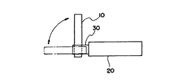
一実施の形態を示す図3および図13により説明すると、本発明は、両側面に取付け部が設けられたディスプレイ本体10と、このディスプレイ本体10の取付け部にそれぞれ螺着される回転部材52a(52b)を有し、ディスプレイ本体10を両側部から保持してスライド移動可能な一対のスライダ50とを備え、回転部材52a(52b)の回転によりディスプレイ本体10がスライダ50に対して回動するようにした車載用ディスプレイ装置に適用され、次の構成により上記問題点を解決する。
ディスプレイ本体10の両側面にはその面の端部から取付け部にかけて取付け用溝13bが形成されるとともに、取付け部には取付け用溝13bと連通する位置決め溝142およびねじ孔13aが設けられ、スライダ50の回転部材52a(52b)には、位置決め溝142に係合される複数のボス522,523および取付け部のねじ孔13aに対応するねじ貫通孔521が設けられ、ボス522,523が取付け用溝13bを通過して位置決め溝142の所定位置に係合されたときにねじ貫通孔521とねじ孔13aとが重なる。
以上の構成において、一対のスライダ50の回転部材52a(52b)に設けられたボス522,523をディスプレイ本体10の取付け用溝13bをそれぞれ通過させて取付け部の位置決め溝142の所定位置に係合させると、回転部材52a(52b)のねじ貫通孔521と取付け部のねじ孔13aとが重なる。この状態でねじをねじ貫通孔521を貫通させてねじ孔13aに螺合すると、ディスプレイ本体10が一対のスライダ50に回動可能に取付けられる。
請求項2の発明は、第1のボス522と、この第1のボス522よりも小径の第2のボス523とを設け、位置決め溝142を、取付け用溝13bに連通し第1のボス522の径と略等しい幅を持つ第1の溝部142aと、第1の溝部142aに連通し第2のボス523の径と略等しい幅を持つ第2の溝部142bとから構成し、第1および第2のボス522,523が第1および第2の溝142a,142bの所定位置にそれぞれ係合されたときにねじ貫通孔521とねじ孔13aとが重なるよう構成したものである。
請求項3の発明は、取付け用溝13のディスプレイ本体側面端部における幅を第1のボス522の径よりも広くしたものである。
【0005】
なお、本発明の構成を説明する上記課題を解決するための手段の項では、本発明を分かり易くするために実施の形態の図を用いたが、これにより本発明が実施の形態に限定されるものではない。
【0006】
【発明の実施の形態】
図1〜図13により本発明の一実施の形態を説明する。
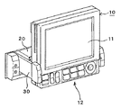
図1および図2は本発明に係る車載用ディスプレイ装置の外観を示す斜視図であり、図1はディスプレイ本体10が車体のコンソール部分に収納された収納状態を、図2はディスプレイ本体10がコンソール部分から突出された使用状態をそれぞれ示している。ディスプレイ本体10は、TV放送あるいはナビゲーションシステムにおける地図情報などを映し出す液晶などの画面11と、種々の操作ボタンから成る操作部12とを有している。図1のBTは、ディスプレイ装置を図1の状態と図2の状態とで切換えるためのオープン/クローズボタンである。
【0007】
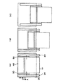
本実施の形態におけるディスプレイ装置の大まかな構成および動きを図3および図4の概略図により説明する。
図3において、20は車体のコンソール部分に埋設されるアッパーケース、30はアッパーケース20に対して車両前後方向(図示A,B方向)にスライド可能に支持される一対のサイドスライダ、40はサイドスライダ30に対してA,B方向に移動可能に支持されるメカベースであり、メカベース40の両端に固着された一対のサイドアーム50の先端にディスプレイ本体10が回動可能に支持される。
【0008】
図1および図3(a)に示す収納状態でオープン/クローズボタンBTが操作されると、メカベース40,サイドアーム50およびディスプレイ本体10が一体にA方向に移動し、図3(b)の状態に達するとサイドスライダ30も一体に移動を開始し、図3(c)の状態(ディスプレイ本体10がコンソールから完全に突出した状態)で停止する。次いで図4に示すようにディスプレイ本体10が上方に回動し、図2に示す使用状態になると停止する。使用状態でオープン/クローズボタンBTが操作されると、上述と逆の動作で収納状態に戻る。
【0009】
上述した動作を実現するための機構を図5〜図13により詳細に説明する。
図5(a)はアッパーケース20および一対のサイドスライダ30を車両下方から見た図、図5(b)はそのb−b線矢視図、図6は図5(a)のVI一VI線拡大矢視図である。
【0010】
アッパーケース20は、上板21,後板22および一対の側板23が一体化されて成り、上板21の内面には左右一対のラック21aが形成されている。各側板23には、図6に示すように一対の長手方向のガイド孔23aと、同じく長手方向の矩形の長孔23bが形成され、長孔23bの上下にレール23cが形成されている。各サイドスライダ30には、一対のローラ31が回転可能に取付けられるとともに、一対のガイドピン32が植設されている。サイドスライダ30は、そのローラ31が側板23の長孔23bを貫通して上下レール23c間に挿通され、かつ一対のガイドピン32が一対のガイド孔23aにそれぞれ係合するよう側板23の内面に沿って配置される。これにより各サイドスライダ30は、アッパーケース20に対してA,B方向にスムーズにスライド可能とされる。
【0011】
各サイドスライダ30にはまた、ローラ33を保持するレバー34が回動可能に支持され、このレバー34はねじりばね35により常に図示時計回り方向、すなわちローラ33が一方のレール23cに押圧される方向に付勢されている。図6(a)のようにサイドスライダ30が最も後方に位置しているときには、ローラ33がばね35の付勢力によりレール23cの切欠23dに落込んでおり、この位置からサイドスライダ30が前方(A方向)に移動するときには、図6(b)に示すようにローラ33がばね35の付勢力に抗してレール23c上に乗り上げる。一方、アッパーケース20の上板21に突設された左右一対のばね掛け21bと、一対のサイドスライダ30のガイドピン32に固着されたばね掛け部材36とには引張ばね37の両端がそれぞれ係止され、このばね37の付勢力により各サイドスライダ30は常に後方に付勢される。
【0012】
図7はメカベース40およびその両端に固着されたサイドアーム50を示す平面図である。メカベース40にはスライドモータ41およびチルトモータ42が固定され、スライドモータ41の回転は減速歯車機構43およびピニオンギア43aを介してピニオンギア43bに伝達される。ピニオンギア43bの回転は、ピニオンシャフト44を介して反対側のピニオンギア43cに伝達される。
【0013】
減速歯車機構43は図8(a)に示すように、スライドモータ41の出力軸に噛合される平歯車431と、この平歯車431に順次に噛合連結される平歯車432〜434とから構成され、平歯車434が図7のピニオンギア43aに噛合される。平歯車431および433はシャフトSH1により、平歯車432および434はシャフトSH2により一方のサイドアーム50とメカベース40に立設された立壁40aとにそれぞれ支持され、またピニオンギア43a,43bは一方のサイドアーム50に、ピニオンギア43cは他方のサイドアーム50にそれぞれ支持される。
【0014】
図8(a)の45は、スライドモータ41の出力軸に直接噛合された平歯車431に回転負荷を与えるロック機構であり、シャフトSH1に外挿された円盤状のフェルト451および押さえ板452と、押さえ板452と立壁40aとの間に介装された押圧ばね453とから成る。押さえ板452は、図8(b)に示すように押圧部452aと腕部452bとから成り、腕部452bがシャフトSH2に支持されている。ばね453の付勢力により押さえ板452がフェルト451を平歯車431に押圧し、平歯車431に回転負荷を与える。これにより、平歯車432側から平歯車431に伝達される回転トルクがばね453のばね力で決る所定値以下の状態では平歯車431は回転しない。
【0015】
図9は上述した平歯車433を含むトルクリミッタ46の構成を示している。平歯車433は大径ギア433aと、この大径ギア433aとは別体の小径ギア433bとから構成され、小径ギア433bの一端が大径ギア433aに設けられた凹部に挿通されている。46aはシャフトSH1に外挿された筒体であり、この筒体46aの一端が大径および小径ギア433a,433bを摺動可能に貫通している。筒体46aの他端に設けられたばね受け46bと小径ギア433bとの間には圧縮ばね46cが介装され、このばね46cの付勢力により小径ギア433bが大径ギア433aに押圧されている。したがって、通常は大径および小径ギア433a,433bは一体に回転するが、小径ギア433bにかかる回転トルクが所定値(ばね46cのばね力で決る)以上になると、小径ギア433bは大径ギア433aに対して回転する。
【0016】
図7において、チルトモータ42の駆動力は、複数の平歯車471〜475から成る減速歯車機構47およびピニオンギア51a,51bを介してディスプレイギア52aに伝達される。またピニオンギア51aの回転は、シャフト53を介して反対側のピニオンギア51cに伝達され、ピニオン51cの回転はピニオンギア51dを介してディスプレイギア52bに伝達される。
【0017】
減速歯車機構47を構成する複数の平歯車471〜475は、サイドアーム50と立壁40aとに支持され、ピニオンギア51a,51bおよびピニオンギア51c,51dは両サイドアーム50の外面にそれぞれ支持されている。ディスプレイギア52a,52bは、両サイドアーム50の先端に形成された孔部に回転可能に嵌合され、その一方の面(ディスプレイ本体10に取付けられる面)がサイドアーム50の内側に露出している。シャフト54の一端側にはねじりばね54が外挿され、このばね54の付勢力によりシャフト53が回転方向に付勢される。
【0018】
図7の48は、図8で説明したロック機構45と同様のロック機構であり、チルトモータ52に直接噛合する平歯車471に回転負荷を与える。また平歯車474は、図9で説明したトルクリミッタ46と同様のトルクリミッタ49を構成する。
【0019】
図10は図7のX−X線矢視図である。一対のサイドアーム50の外面には、前後の角部に各一対のローラ55がそれぞれ回転可能に軸支されるとともに、ローラ56を有する板部材57が軸57a回りに回動可能に取付けられ、板部材57はばね58により図示時計回り方向に付勢されている。これらのローラ55,56,板部材57およびばね58は、サイドアーム50のガタを防止するためのものであり、その詳細な機能は後述する。
【0020】
メカベース40は、図7に示す一対のピニオンギア43b,43cが上述したアッパーケース20(図5)の上板21に形成された一対のラック21aにそれぞれ噛合されるように一対のサイドスライダ30の間に挿通される。このピニオンギア43b,43cとラック21aとの噛合により、メカベース40は図3(a)の位置と図3(c)の位置との間でアッパーケース20に対して移動可能とされる。メカベース40の両端のサイドアーム50は、両サイドスライダ30の内面に沿ってそれぞれ配置され、図11に示すようにサイドアーム50の4つのローラ55がサイドスライダ30の上下レール38に当接される。
【0021】
次に、一対のサイドアーム50にディスプレイ本体10を取付けるための取付構造を説明する。
図12,図13に示すように、ディスプレイ本体10のケース13(樹脂により構成される)の両側面には、金属製の取付け板14が螺着されるとともに、この取付け板14からディスプレイ本体下端部にかけて取付け溝13bが形成されている。取付け板14には、ケース13に形成された複数のねじ孔13aと連通する複数の貫通孔141と、上記取付け溝13bに連通する位置決め孔142とが形成されている。位置決め孔142は幅の広い基端部142aと、幅の狭い先端部142bとから成り、それらの境界部分は緩やかな曲面とされている。ケース13の取付け溝13bは、図示の如く端部に至るほど幅が広くなるテーパー部を有している。
【0022】
一方、サイドアーム50の先端に設けられた上記ディスプレイギア52a,52bには、複数のねじ貫通孔521が形成されるとともに、その内面(ディスプレイ本体10側の面)に大径および小径のボス522,523が突設されている。小径のボス523はディスプレイギア52a,52bの回転中心に設けられ、大径のボス522は中心から偏心した位置に設けられる。大径ボス522の径は、位置決め孔142の基端部142aの幅と略同一とされ、小径ボス521の径は、位置決め孔142の先端部142bと略同一とされる。
【0023】
ディスプレイ本体10の取付けにあたり、ディスプレイ本体10の下部を一対のサイドアーム50間に挿通する。その際、両サイドアーム50のディスプレイギア52a,52bに突設されたボス522,533がディスプレイ本体10の取付け溝13b内を通過するようにディスプレイ本体10を移動させる。取付け溝13bの先端にはテーパー部が形成されているので、溝13b内にボス522,523を挿入させるのが容易に行えるとともに、挿入されたボス522,523を溝13bの中心側に容易に案内することができる。次いでボス522,523は溝13bから取付け板14の位置決め溝142に移動し、図示破線の如く溝142の基端部142aおよび先端部142bの先端に係合される。基端部142aの先端壁面は緩やかな曲面となっているので、小径ボス523を容易に溝先端部142bに案内することができる。
【0024】
ボス522,523が溝142にそれぞれ係合されたとき、図示の如くディスプレイギア52a,52bの複数のねじ貫通孔521と、取付け板14のねじ貫通孔141およびケース13のねじ孔13aとが重なり、ここにビスBSをそれぞれ貫通して螺合する。これにより一対のサイドアーム50にディスプレイ本体10が取付けられ、ディスプレイギア52a,52bの回転によりディスプレイ本体10がサイドアーム50に対して回動可能となる。
以上のように構成されたディスプレイ装置は、アッパーケース20がコンソール部分に埋設されることにより車体に設置される。
【0025】
次に、ディスプレイ装置の動作を詳細に説明する。
図1および図3(a)に示す収納状態では、各サイドスライダ30が最も後方に位置しており、図6(a)に示すように各ローラ33がばね35の付勢力によりレール23cの切欠23dに落込んで切欠23dの前後エッジ部を押圧している。これによりサイドスライダ30は、ローラ33を介して図示下方(車両搭載状態では上方)に付勢されることになり、車両の振動等に起因するサイドスライダ30のアッパーケース20に対する上下方向のガタが防止される。このとき、ばね37は最も緩んだ状態となっているが、上記ローラ33が切欠23dの前後エッジ部を押圧することによりサイドスライダ30の前後方向のガタも防止される。
【0026】
一方、図11(a)に示すように一対のサイドアーム50も最も後方に位置しており、ローラ56はばね58の付勢力によりサイドスライダ30のレール38に押し付けられている。これによりサイドアーム50は、ローラ56を介して図示上方(車両搭載状態では下方)に付勢されることになり、サイドアーム50のサイドスライダ30に対する上下方向のガタが防止される。
【0027】
オープン/クローズボタンBTが操作されると、スライドモータ41(図7)が所定方向に回転され、その回転は減速歯車機構43およびピニオンギア43aを介してピニオンギア43bに伝達されるとともに、ピニオンシャフト44を介してピニオンギア43cにも伝達される。したがって、ピニオンギア43b,43cがラック21a上を移動することによりメカベース40,サイドアーム50およびディスプレイ本体10が一体に図3のA方向にスライド移動する。その際、図11(a)に示す各4個のローラ55がサイドスライダ30のレール38上を摺動するので、各サイドアーム50はスムーズに移動できる。また、ローラ56はばね85の付勢力によりレール38に押し付けられたまま回転するので、移動中もサイドアーム50の上下方向のガタが防止される。
【0028】
図3(b)および図11(b)に示すように、左右一対のサイドアーム50の先端がサイドスライダ30の先端にほぼ一致したとき、左右のローラ56がばね58の付勢力によりレール38の切欠38aに同時に落込み、切欠38aの前後エッジ部に押圧される。またこのとき、ローラ56は後部下端のローラ55に当接し、両ローラ56,55の回転に負荷が加わる。この2つの作用により各サイドスライダ30は各サイドアーム50に引きずられるようにして一体に前方に移動を開始する。その際、図6(b)に示すように双方のサイドスライダ30のローラ33は、ばね35の付勢力に抗して切欠23dから同時にレール23c上に乗り上げる。このように左右のローラ56が切欠38aに同時に落込み、かつ左右のローラ33が切欠32dから同時に脱出するようにしたので、双方のサイドスライダ30を時間的にずれなく同時に移動開始することができ、スムーズな移動が達成される。
【0029】
また、ローラ33は、切欠23dから脱出した後もレール23cを押圧しつつ回転するので、移動中もサイドスライダ30の上下方向のガタが防止される。さらにサイドスライダ30はばね37の付勢力に抗して移動することになるので、ばね37の付勢力によりサイドスライダ30の前後方向のガタも防止される。
【0030】
図3(c)に示すように、ディスプレイ本体10がコンソールから完全に突出すると、スライドモータ41が停止され、代ってチルトモータ42が所定方向に回転される。チルトモータ42の回転は、上述した減速歯車機構47(図7)およびピニオンギア51a,51bを介してディスプレイギア52aに伝達されるとともに、シャフト53およびピニオンギア51c,51dを介してディスプレイギア52bに伝達され、両ディスプレイギア52a,52bが同期して回転する。これにより、ディスプレイギア52a,52bと一体化されたディスプレイ本体10が図4に示す如く回動し、所定位置(乗員が画面を視認可能な位置)に達するとチルトモータ42が停止される。ディスプレイ本体10は、図7のシャフト53に外挿されたねじりばね54の作用により常に回動方向に付勢されるので、ディスプレイ本体10の回動方向のガタが防止される。
なお、ディスプレイ本体10の前後位置および回動位置は、操作部12に設けられた操作部材を操作してスライド/チルトモータ41,42を回転させることにより適宜調節できる。
【0031】
ここで、上記スライドモータ41に直接噛合された平歯車431には、ロック機構45により負荷が与えられているので、車体の振動程度ではサイドアーム50、すなわちディスプレイ本体10が車両前後方向に不所望に移動することはない。一方、乗員がディスプレイ本体10の前後位置を調整すべく所定値以上の力でディスプレイ本体10を押した場合、各平歯車431〜434がロック機構45による負荷に抗してスライドモータ41を回転させつつ回転し、これによりディスプレイ本体10の移動が許容される。その際、平歯車431はロック機構45を構成するフェルト451に対して摺動しつつ回転することになる。
【0032】
同様にチルトモータ42に直接噛合された平歯車431には、ロック機構48により負荷が与えられているので、車体の振動程度ではディスプレイ本体10がサイドアーム50に対して不所望に回動することはない。したがって、ディスプレイ本体10の背面をコンソールに当接させることなく、所望の位置で保持することができる。一方、乗員がディスプレイ本体10の回動位置を調整すべく所定値以上の力でディスプレイ本体10を回動しようとした場合、各平歯車471〜475がロック機構48による負荷に抗してチルトモータ42を回転させつつ回転し、これによりディスプレイ本体10の回動が許容される。
【0033】
また、何らかの原因でディスプレイ本体10に車両前後方向の大きな外力(乗員が手で押込もうとする力よりも大きな力)が作用すると、トルクリミッタ46を構成する歯車433bが歯車433aに対して回転し、これによりディスプレイ本体10からスライドモータ41への回転トルクの伝達が断たれた状態でサイドアーム50がスライドし、ディスプレイ本体10が移動する。同様にディスプレイ本体10に回動方向の大きな外力(乗員が手で回動させようとする力よりも大きな力)が作用すると、上述したトルクリミッタの作用により、ディスプレイ本体10からチルトモータ42への回転トルクの伝達が断たれた状態でディスプレイ本体10が回動する。
【0034】
ディスプレイ装置の使用状態でオープン/クローズボタンBTが操作されると、チルトモータ42が駆動されてディスプレイ本体10が図4の二点鎖線の位置まで回動し、次いでスライドモータ41が駆動されてディスプレイ本体10,サイドアーム50,メカベース40およびサイドスライダ30が図3(c)の状態から一体にB方向にスライド移動する。図3(b)の状態に達すると、サイドスライダ30の後端部がアッパーケース20の後板22に当接してその移動が停止し、以降はディスプレイ本体10,サイドアーム50およびメカベース40のみが移動することになる。その際、図6(a)に示すようにサイドスライダ30のローラ33がばね35の付勢力によりアッパーケース20の切欠23dに落込んで掛止される一方、サイドスライダ30の切欠38a(図11(c))に掛止されていたサイドアーム50のローラ56がばね58の付勢力に抗して切欠38aから外れてレール38上に乗り上げ、以降ローラ56はレール38上を回転しつつ移動する。その後、図3(a)の状態に達するとスライドモータ41が停止される。
【0035】
以上の実施例の構成において、ディスプレイギア52a,52bが回転部材を、サイドアーム50がスライダを、ボス522が第1のボスを、ボス523が第2のボス523を、溝142の基端部142aが第1の溝部を、先端部142bが第2の溝部をそれぞれ構成する。
なお、ディスプレイギアに形成される複数のボスの大きさおよび溝の形状は適宜変更可能である。
【0036】
【発明の効果】
本発明によれば、一対のスライダに設けられた回転部材のボスをディスプレイ本体側の取付け溝を通過させて案内溝に係合させると、回転部材のねじ貫通孔とディスプレイ本体側のねじ孔とが重なるよう構成したので、ディスプレイ本体を一対のスライダに容易に取付けることができ、組立作業効率の向上が図れる。
【図面の簡単な説明】
【図1】本発明に係るディスプレイ装置の収納状態を示す斜視図。
【図2】上記ディスプレイ装置の突出状態(使用状態)を示す斜視図。
【図3】ディスプレイ装置のスライド動作を説明する図。
【図4】ディスプレイ装置の回動動作を説明する図。
【図5】アッパーケースの構成を示す平面図およびそのb−b線矢視図。
【図6】図5のVI一VI線から見た拡大図。
【図7】ディスプレイ本体のスライドおよび回動駆動機構を示す図。
【図8】図7の減速歯車機構の詳細を示す平面図およびそのb−b線矢視図。
【図9】トルクリミッタの構成を示す拡大図。
【図10】図7のX−X線拡大矢視図。
【図11】サイドアームのサイドスライダに対する動きを説明する図。
【図12】ディスプレイ本体の側面を示す図。
【図13】(b)はディスプレイ本体の取付け構造を示す側面図であり、(a)は(b)のa−a線断面図。
【符号の説明】
10 ディスプレイ本体
11 画面
12 操作部
13 ケース
13a ねじ孔
13b 取付け溝
14 取付け板
20 アッパーケース
21a ラック
23 側板
23c レール
23d 切欠
30 サイドスライダ
31,33 ローラ
34 レバー
35 ねじりばね
37 引張ばね
38 レール
38a 切欠
40 メカベース
41 スライドモータ
42 チルトモータ
43,47 減速歯車機構
43a〜43c ピニオンギア
44 ピニオンシャフト
45,48 ロック機構
46,49 トルクリミッタ
50 サイドアーム
51a〜51d ピニオンギア
52a,52b ディスプレイギア
53 シャフト
54 ねじりばね
55,56 ローラ
57 板部材
58 引張ばね
141 ねじ貫通孔
142 位置決め溝
521 ねじ貫通孔
522, 523 ボス
[0001]
BACKGROUND OF THE INVENTION
The present invention relates to an in-vehicle display device that is mounted on a vehicle and displays map information of a television broadcast or a navigation system.
[0002]
[Prior art and its problems]
As a display device mounted on a vehicle, a display device is housed in a console portion of a vehicle body when not in use, and in use, the display body is pulled out from the console portion and rotated to a state where a passenger can visually recognize it. ing. This type of display apparatus has a slider that holds the display body and is slidable in the longitudinal direction of the vehicle, and the display body is rotatably attached to the tip of the slider. Conventionally, there has been a problem that the work for attaching the display body to the slider is complicated in the manufacturing process.
[0003]
An object of the present invention is to provide an in-vehicle display device that simplifies the process of attaching a display body to a slider and improves assembly efficiency.
[0004]
[Means for Solving the Problems]
3 and FIG. 13 showing an embodiment, the present invention relates to a display main body 10 provided with attachment portions on both side surfaces and rotating members 52a (which are respectively screwed to the attachment portions of the display main body 10). 52b), and a pair of sliders 50 that can slide while holding the display main body 10 from both sides, and the display main body 10 is rotated with respect to the slider 50 by the rotation of the rotating member 52a (52b). The above-described problem is solved by the following configuration.
A mounting groove 13b is formed on both sides of the display body 10 from the end of the surface to the mounting portion, and a positioning groove 142 and a screw hole 13a communicating with the mounting groove 13b are provided on the mounting portion. The 50 rotation members 52a (52b) are provided with a plurality of bosses 522, 523 engaged with the positioning groove 142 and screw through holes 521 corresponding to the screw holes 13a of the mounting portion, and the bosses 522, 523 are for mounting. When passing through the groove 13b and being engaged with a predetermined position of the positioning groove 142, the screw through hole 521 and the screw hole 13a overlap.
In the above configuration, the bosses 522 and 523 provided on the rotating members 52a (52b) of the pair of sliders 50 are respectively passed through the mounting grooves 13b of the display body 10 and engaged with the predetermined positions of the positioning grooves 142 of the mounting portion. As a result, the screw through hole 521 of the rotating member 52a (52b) and the screw hole 13a of the mounting portion overlap. In this state, when the screw is passed through the screw through hole 521 and screwed into the screw hole 13a, the display body 10 is rotatably attached to the pair of sliders 50.
According to the second aspect of the present invention, the first boss 522 and the second boss 523 having a smaller diameter than the first boss 522 are provided, and the positioning groove 142 is communicated with the mounting groove 13b. A first groove 142a having a width substantially equal to the diameter of the first groove 142a and a second groove 142b communicating with the first groove 142a and having a width substantially equal to the diameter of the second boss 523. When the two bosses 522 and 523 are respectively engaged with predetermined positions of the first and second grooves 142a and 142b, the screw through hole 521 and the screw hole 13a are configured to overlap each other.
According to the third aspect of the present invention, the width of the mounting groove 13 at the side end of the display main body is wider than the diameter of the first boss 522.
[0005]
In the section of the means for solving the above-described problem to explain the configuration of the present invention, the drawings of the embodiments are used for easy understanding of the present invention, but the present invention is thereby limited to the embodiments. It is not something.
[0006]
DETAILED DESCRIPTION OF THE INVENTION
An embodiment of the present invention will be described with reference to FIGS.
1 and 2 are perspective views showing the appearance of an in-vehicle display device according to the present invention. FIG. 1 shows a storage state in which a display main body 10 is stored in a console portion of a vehicle body, and FIG. The use state protruded from the part is shown. The display main body 10 includes a screen 11 such as a liquid crystal for displaying map information in a TV broadcast or a navigation system, and an operation unit 12 including various operation buttons. BT of FIG. 1 is an open / close button for switching the display device between the state of FIG. 1 and the state of FIG.
[0007]
The general configuration and movement of the display device according to the present embodiment will be described with reference to the schematic diagrams of FIGS.
In FIG. 3, 20 is an upper case embedded in the console portion of the vehicle body, 30 is a pair of side sliders supported by the upper case 20 so as to be slidable in the vehicle longitudinal direction (A and B directions in the figure), and 40 is a side. The mechanical base is supported so as to be movable in the A and B directions with respect to the slider 30, and the display main body 10 is rotatably supported at the distal ends of a pair of side arms 50 fixed to both ends of the mechanical base 40.
[0008]
When the open / close button BT is operated in the storage state shown in FIGS. 1 and 3A, the mechanical base 40, the side arm 50, and the display body 10 are integrally moved in the A direction, and the state shown in FIG. When reaching the side slider 30, the side slider 30 also starts to move together, and stops in the state shown in FIG. 3C (the display main body 10 completely protrudes from the console). Next, as shown in FIG. 4, the display main body 10 rotates upward and stops when the use state shown in FIG. 2 is reached. When the open / close button BT is operated in the use state, the storage state is restored by the reverse operation to that described above.
[0009]
A mechanism for realizing the above-described operation will be described in detail with reference to FIGS.
5A is a view of the upper case 20 and the pair of side sliders 30 as viewed from the lower side of the vehicle, FIG. 5B is a view taken along line bb, and FIG. 6 is a VI VI of FIG. 5A. FIG.
[0010]
The upper case 20 is formed by integrating an upper plate 21, a rear plate 22, and a pair of side plates 23, and a pair of left and right racks 21 a are formed on the inner surface of the upper plate 21. As shown in FIG. 6, each side plate 23 is formed with a pair of guide holes 23a in the longitudinal direction and rectangular long holes 23b in the same longitudinal direction, and rails 23c are formed above and below the long holes 23b. A pair of rollers 31 is rotatably attached to each side slider 30 and a pair of guide pins 32 are implanted. The side slider 30 is formed on the inner surface of the side plate 23 so that the roller 31 passes through the long hole 23b of the side plate 23 and is inserted between the upper and lower rails 23c, and the pair of guide pins 32 engage with the pair of guide holes 23a, respectively. Arranged along. Thereby, each side slider 30 can be smoothly slid in the A and B directions with respect to the upper case 20.
[0011]
Each side slider 30 also rotatably supports a lever 34 that holds a roller 33. The lever 34 is always rotated clockwise by a torsion spring 35, that is, a direction in which the roller 33 is pressed against one rail 23c. Is being energized. When the side slider 30 is located at the rearmost position as shown in FIG. 6A, the roller 33 is dropped into the notch 23d of the rail 23c by the urging force of the spring 35, and the side slider 30 moves forward (A When moving in the direction), the roller 33 rides on the rail 23c against the urging force of the spring 35 as shown in FIG. On the other hand, both ends of the tension spring 37 are locked to the pair of left and right spring hooks 21b protruding from the upper plate 21 of the upper case 20 and the spring hook member 36 fixed to the guide pins 32 of the pair of side sliders 30, respectively. The side sliders 30 are always urged rearward by the urging force of the springs 37.
[0012]
FIG. 7 is a plan view showing the mechanical base 40 and the side arms 50 fixed to both ends thereof. A slide motor 41 and a tilt motor 42 are fixed to the mechanical base 40, and the rotation of the slide motor 41 is transmitted to the pinion gear 43b via the reduction gear mechanism 43 and the pinion gear 43a. The rotation of the pinion gear 43b is transmitted to the opposite pinion gear 43c via the pinion shaft 44.
[0013]
As shown in FIG. 8A, the reduction gear mechanism 43 includes a spur gear 431 that meshes with the output shaft of the slide motor 41 and spur gears 432 to 434 that are sequentially meshed with the spur gear 431. The spur gear 434 is meshed with the pinion gear 43a of FIG. The spur gears 431 and 433 are supported by the shaft SH1, the spur gears 432 and 434 are supported by the shaft SH2 on one side arm 50 and the upright wall 40a erected on the mechanical base 40, and the pinion gears 43a and 43b are supported on one side. The pinion gear 43c is supported by the arm 50 and the other side arm 50, respectively.
[0014]
Reference numeral 45 in FIG. 8A denotes a lock mechanism that applies a rotational load to the spur gear 431 that is directly meshed with the output shaft of the slide motor 41. The disc-shaped felt 451 and presser plate 452 that are extrapolated to the shaft SH1; , And a pressing spring 453 interposed between the pressing plate 452 and the standing wall 40a. As shown in FIG. 8B, the pressing plate 452 includes a pressing portion 452a and an arm portion 452b, and the arm portion 452b is supported by the shaft SH2. The pressing plate 452 presses the felt 451 against the spur gear 431 by the urging force of the spring 453 and applies a rotational load to the spur gear 431. Thus, the spur gear 431 does not rotate in a state where the rotational torque transmitted from the spur gear 432 side to the spur gear 431 is equal to or less than a predetermined value determined by the spring force of the spring 453.
[0015]
FIG. 9 shows the configuration of the torque limiter 46 including the spur gear 433 described above. The spur gear 433 includes a large-diameter gear 433a and a small-diameter gear 433b separate from the large-diameter gear 433a, and one end of the small-diameter gear 433b is inserted into a recess provided in the large-diameter gear 433a. Reference numeral 46a denotes a cylindrical body that is extrapolated to the shaft SH1, and one end of the cylindrical body 46a penetrates through the large and small diameter gears 433a and 433b. A compression spring 46c is interposed between a spring receiver 46b provided at the other end of the cylindrical body 46a and a small diameter gear 433b, and the small diameter gear 433b is pressed against the large diameter gear 433a by the urging force of the spring 46c. Therefore, normally, the large-diameter and small-diameter gears 433a and 433b rotate integrally, but when the rotational torque applied to the small-diameter gear 433b exceeds a predetermined value (determined by the spring force of the spring 46c), the small-diameter gear 433b becomes large-diameter gear 433a. Rotate against.
[0016]
In FIG. 7, the driving force of the tilt motor 42 is transmitted to the display gear 52a via the reduction gear mechanism 47 including a plurality of spur gears 471 to 475 and the pinion gears 51a and 51b. The rotation of the pinion gear 51a is transmitted to the opposite pinion gear 51c via the shaft 53, and the rotation of the pinion 51c is transmitted to the display gear 52b via the pinion gear 51d.
[0017]
A plurality of spur gears 471 to 475 constituting the reduction gear mechanism 47 are supported by the side arm 50 and the standing wall 40a, and the pinion gears 51a and 51b and the pinion gears 51c and 51d are respectively supported by the outer surfaces of the side arms 50. Yes. The display gears 52a and 52b are rotatably fitted in holes formed at the tips of both side arms 50, and one surface thereof (the surface attached to the display body 10) is exposed inside the side arm 50. Yes. A torsion spring 54 is extrapolated to one end side of the shaft 54, and the shaft 53 is biased in the rotational direction by the biasing force of the spring 54.
[0018]
Reference numeral 48 in FIG. 7 denotes a lock mechanism similar to the lock mechanism 45 described in FIG. 8, and applies a rotational load to the spur gear 471 that directly meshes with the tilt motor 52. The spur gear 474 constitutes a torque limiter 49 similar to the torque limiter 46 described in FIG.
[0019]
FIG. 10 is a view taken along line XX in FIG. On the outer surfaces of the pair of side arms 50, a pair of rollers 55 are rotatably supported at the front and rear corners, and a plate member 57 having the rollers 56 is rotatably attached around a shaft 57a. The plate member 57 is biased clockwise by a spring 58 in the drawing. These rollers 55 and 56, the plate member 57, and the spring 58 are for preventing the side arm 50 from rattling, and their detailed functions will be described later.
[0020]
The mechanical base 40 has a pair of side sliders 30 so that the pair of pinion gears 43b and 43c shown in FIG. 7 are respectively engaged with the pair of racks 21a formed on the upper plate 21 of the upper case 20 (FIG. 5). It is inserted between. By meshing the pinion gears 43b and 43c with the rack 21a, the mechanical base 40 is movable with respect to the upper case 20 between the position shown in FIG. 3A and the position shown in FIG. The side arms 50 at both ends of the mechanical base 40 are respectively disposed along the inner surfaces of the side sliders 30, and the four rollers 55 of the side arms 50 come into contact with the upper and lower rails 38 of the side slider 30 as shown in FIG. 11. .
[0021]
Next, an attachment structure for attaching the display body 10 to the pair of side arms 50 will be described.
As shown in FIGS. 12 and 13, a metal mounting plate 14 is screwed to both side surfaces of the case 13 (made of resin) of the display main body 10, and the display body lower end is provided from the mounting plate 14. A mounting groove 13b is formed over the portion. The mounting plate 14 is formed with a plurality of through holes 141 communicating with the plurality of screw holes 13a formed in the case 13, and a positioning hole 142 communicating with the mounting groove 13b. The positioning hole 142 includes a wide base end part 142a and a narrow front end part 142b, and the boundary part thereof is a gently curved surface. The mounting groove 13b of the case 13 has a tapered portion that becomes wider as it reaches the end as shown in the figure.
[0022]
On the other hand, a plurality of screw through holes 521 are formed in the display gears 52a and 52b provided at the distal ends of the side arms 50, and large and small diameter bosses 522 are formed on the inner surfaces (the surfaces on the display body 10 side). , 523 are projected. The small-diameter boss 523 is provided at the rotation center of the display gears 52a and 52b, and the large-diameter boss 522 is provided at a position eccentric from the center. The diameter of the large-diameter boss 522 is substantially the same as the width of the base end portion 142 a of the positioning hole 142, and the diameter of the small-diameter boss 521 is substantially the same as the distal end portion 142 b of the positioning hole 142.
[0023]
In attaching the display body 10, the lower part of the display body 10 is inserted between the pair of side arms 50. At that time, the display main body 10 is moved so that the bosses 522 and 533 protruding from the display gears 52 a and 52 b of both side arms 50 pass through the mounting grooves 13 b of the display main body 10. Since a tapered portion is formed at the tip of the mounting groove 13b, the bosses 522 and 523 can be easily inserted into the groove 13b, and the inserted bosses 522 and 523 can be easily placed on the center side of the groove 13b. I can guide you. Next, the bosses 522 and 523 move from the groove 13b to the positioning groove 142 of the mounting plate 14, and are engaged with the distal ends of the proximal end portion 142a and the distal end portion 142b of the groove 142 as shown by broken lines in the figure. Since the distal end wall surface of the base end portion 142a is a gently curved surface, the small diameter boss 523 can be easily guided to the groove distal end portion 142b.
[0024]
When the bosses 522 and 523 are respectively engaged with the grooves 142, the plurality of screw through holes 521 of the display gears 52a and 52b overlap with the screw through holes 141 of the mounting plate 14 and the screw holes 13a of the case 13 as shown in the figure. The screws BS are threaded through the screws BS, respectively. Accordingly, the display main body 10 is attached to the pair of side arms 50, and the display main body 10 can be rotated with respect to the side arms 50 by the rotation of the display gears 52a and 52b.
The display device configured as described above is installed on the vehicle body by the upper case 20 being embedded in the console portion.
[0025]
Next, the operation of the display device will be described in detail.
In the storage state shown in FIGS. 1 and 3A, each side slider 30 is located at the rearmost position, and as shown in FIG. 6A, each roller 33 is notched in the rail 23c by the biasing force of the spring 35. 23d to press the front and rear edge portions of the notch 23d. As a result, the side slider 30 is urged downward in the figure (upward in a vehicle-mounted state) via the roller 33, and there is a backlash in the vertical direction with respect to the upper case 20 of the side slider 30 due to vibration of the vehicle and the like. Is prevented. At this time, the spring 37 is in the most loose state, but the backlash of the side slider 30 in the front-rear direction is also prevented by the roller 33 pressing the front-rear edge part of the notch 23d.
[0026]
On the other hand, as shown in FIG. 11A, the pair of side arms 50 is also located at the rearmost position, and the roller 56 is pressed against the rail 38 of the side slider 30 by the urging force of the spring 58. As a result, the side arm 50 is urged upward in the figure (downward in the vehicle-mounted state) via the roller 56, and the backlash of the side arm 50 with respect to the side slider 30 is prevented.
[0027]
When the open / close button BT is operated, the slide motor 41 (FIG. 7) is rotated in a predetermined direction, and the rotation is transmitted to the pinion gear 43b via the reduction gear mechanism 43 and the pinion gear 43a and the pinion shaft. It is also transmitted to the pinion gear 43c via 44. Therefore, when the pinion gears 43b and 43c move on the rack 21a, the mechanical base 40, the side arm 50, and the display main body 10 slide together in the direction A in FIG. At this time, each of the four rollers 55 shown in FIG. 11A slides on the rail 38 of the side slider 30, so that each side arm 50 can move smoothly. Further, since the roller 56 rotates while being pressed against the rail 38 by the urging force of the spring 85, the side arm 50 is prevented from rattling in the vertical direction even during movement.
[0028]
As shown in FIGS. 3B and 11B, when the tips of the pair of left and right side arms 50 substantially coincide with the tips of the side sliders 30, the left and right rollers 56 are moved by the biasing force of the springs 58. It falls into the notch 38a at the same time and is pressed by the front and rear edge portions of the notch 38a. At this time, the roller 56 contacts the roller 55 at the lower end of the rear portion, and a load is applied to the rotation of both the rollers 56 and 55. With these two actions, each side slider 30 starts to move forward integrally as being dragged by each side arm 50. At that time, as shown in FIG. 6B, the rollers 33 of both side sliders 30 ride on the rails 23 c simultaneously from the notches 23 d against the urging force of the springs 35. As described above, the left and right rollers 56 simultaneously drop into the notch 38a and the left and right rollers 33 escape from the notch 32d at the same time, so that both side sliders 30 can start to move simultaneously without time lag. Smooth movement is achieved.
[0029]
In addition, since the roller 33 rotates while pressing the rail 23c even after it escapes from the notch 23d, the side slider 30 is prevented from rattling in the vertical direction even during movement. Further, since the side slider 30 moves against the urging force of the spring 37, backlash in the front-rear direction of the side slider 30 is also prevented by the urging force of the spring 37.
[0030]
As shown in FIG. 3C, when the display main body 10 completely protrudes from the console, the slide motor 41 is stopped, and the tilt motor 42 is rotated in a predetermined direction instead. The rotation of the tilt motor 42 is transmitted to the display gear 52a via the reduction gear mechanism 47 (FIG. 7) and the pinion gears 51a and 51b described above, and to the display gear 52b via the shaft 53 and the pinion gears 51c and 51d. The two display gears 52a and 52b are rotated in synchronization with each other. As a result, the display main body 10 integrated with the display gears 52a and 52b rotates as shown in FIG. 4, and the tilt motor 42 is stopped when the display main body 10 reaches a predetermined position (position where the passenger can visually recognize the screen). Since the display body 10 is always urged in the rotation direction by the action of the torsion spring 54 externally attached to the shaft 53 of FIG. 7, the play in the rotation direction of the display body 10 is prevented.
The front-rear position and the rotation position of the display body 10 can be adjusted as appropriate by operating the operation member provided in the operation unit 12 and rotating the slide / tilt motors 41 and 42.
[0031]
Here, since the load is applied to the spur gear 431 directly meshed with the slide motor 41 by the lock mechanism 45, the side arm 50, that is, the display main body 10 is not desired in the vehicle front-rear direction with respect to the vibration of the vehicle body. Never move on. On the other hand, when the occupant pushes the display main body 10 with a force equal to or greater than a predetermined value to adjust the front / rear position of the display main body 10, the spur gears 431 to 434 rotate the slide motor 41 against the load of the lock mechanism 45. The display main body 10 is allowed to move. At this time, the spur gear 431 rotates while sliding with respect to the felt 451 constituting the lock mechanism 45.
[0032]
Similarly, since the load is applied to the spur gear 431 directly meshed with the tilt motor 42 by the lock mechanism 48, the display main body 10 undesirably rotates with respect to the side arm 50 with the degree of vibration of the vehicle body. There is no. Therefore, the back surface of the display main body 10 can be held at a desired position without being brought into contact with the console. On the other hand, when the occupant tries to rotate the display body 10 with a force equal to or greater than a predetermined value in order to adjust the rotation position of the display body 10, each spur gear 471 to 475 resists the load applied by the lock mechanism 48 and the tilt motor. The display main body 10 is allowed to rotate by rotating while rotating 42.
[0033]
Further, when a large external force in the vehicle front-rear direction is applied to the display body 10 for some reason (a force larger than the force that the occupant attempts to push in by hand), the gear 433b constituting the torque limiter 46 rotates with respect to the gear 433a. Thus, the side arm 50 slides in a state where the transmission of the rotational torque from the display main body 10 to the slide motor 41 is cut off, and the display main body 10 moves. Similarly, when a large external force in the rotation direction (a force greater than the force that the occupant attempts to rotate by hand) is applied to the display main body 10, the display main body 10 moves to the tilt motor 42 by the action of the torque limiter described above. The display main body 10 rotates in a state where the transmission of the rotational torque is cut off.
[0034]
When the open / close button BT is operated while the display device is in use, the tilt motor 42 is driven to rotate the display body 10 to the position of the two-dot chain line in FIG. 4, and then the slide motor 41 is driven to display the display. The main body 10, the side arm 50, the mechanical base 40, and the side slider 30 are integrally slid in the B direction from the state shown in FIG. When the state shown in FIG. 3B is reached, the rear end portion of the side slider 30 comes into contact with the rear plate 22 of the upper case 20, and the movement stops. Thereafter, only the display main body 10, the side arm 50, and the mechanical base 40 are present. Will move. At this time, as shown in FIG. 6A, the roller 33 of the side slider 30 falls into the notch 23d of the upper case 20 by the urging force of the spring 35 and is latched, while the notch 38a of the side slider 30 (FIG. c)), the roller 56 of the side arm 50 that has been hooked is disengaged from the notch 38a against the biasing force of the spring 58 and rides on the rail 38. Thereafter, the roller 56 moves while rotating on the rail 38. Thereafter, when the state shown in FIG. 3A is reached, the slide motor 41 is stopped.
[0035]
In the configuration of the above embodiment, the display gears 52a and 52b are rotating members, the side arm 50 is a slider, the boss 522 is a first boss, the boss 523 is a second boss 523, and the base end of the groove 142. 142a constitutes the first groove part, and the tip part 142b constitutes the second groove part.
Note that the size of the plurality of bosses and the shape of the grooves formed in the display gear can be changed as appropriate.
[0036]
【The invention's effect】
According to the present invention, when the boss of the rotating member provided on the pair of sliders is passed through the mounting groove on the display body side and engaged with the guide groove, the screw through hole of the rotating member and the screw hole on the display body side The display main body can be easily attached to the pair of sliders, and the assembly work efficiency can be improved.
[Brief description of the drawings]
FIG. 1 is a perspective view showing a storage state of a display device according to the present invention.
FIG. 2 is a perspective view showing a protruding state (usage state) of the display device.
FIG. 3 is a diagram illustrating a sliding operation of the display device.
FIG. 4 is a diagram for explaining a rotation operation of the display device.
FIG. 5 is a plan view showing a configuration of an upper case and a view taken along line bb.
6 is an enlarged view taken along line VI-VI in FIG. 5;
FIG. 7 is a view showing a slide and rotation drive mechanism of the display main body.
8 is a plan view showing details of the reduction gear mechanism of FIG. 7 and a view taken along the line bb.
FIG. 9 is an enlarged view showing a configuration of a torque limiter.
10 is an enlarged view taken along line XX in FIG.
FIG. 11 is a diagram illustrating the movement of the side arm with respect to the side slider.
FIG. 12 is a diagram showing a side surface of a display main body.
FIG. 13B is a side view showing the mounting structure of the display body, and FIG. 13A is a sectional view taken along line aa in FIG.
[Explanation of symbols]
DESCRIPTION OF SYMBOLS 10 Display main body 11 Screen 12 Operation part 13 Case 13a Screw hole 13b Mounting groove 14 Mounting plate 20 Upper case 21a Rack 23 Side plate 23c Rail 23d Notch 30 Side slider 31, 33 Roller 34 Lever 35 Torsion spring 37 Tension spring 38 Rail 38a Notch 40 Mechanical base 41 Slide motor 42 Tilt motor 43, 47 Reduction gear mechanism 43a-43c Pinion gear 44 Pinion shaft 45, 48 Lock mechanism 46, 49 Torque limiter 50 Side arm 51a-51d Pinion gear 52a, 52b Display gear 53 Shaft 54 Torsion spring 55 56 Roller 57 Plate member 58 Tension spring 141 Screw through hole 142 Positioning groove 521 Screw through hole 522, 523 Boss

Claims (3)

両側面に取付け部が設けられたディスプレイ本体と、このディスプレイ本体の前記取付け部にそれぞれ螺着される回転部材を有し、前記ディスプレイ本体を両側部から保持してスライド移動可能な一対のスライダとを備え、前記回転部材の回転により前記ディスプレイ本体が前記スライダに対して回動するようにした車載用ディスプレイ装置であって、
前記ディスプレイ本体の両側面にはその面の端部から前記取付け部にかけて取付け用溝が形成されるとともに、前記取付け部には前記取付け用溝と連通する位置決め溝およびねじ孔が設けられ、前記スライダの前記回転部材には、前記位置決め溝に係合される複数のボスおよび前記取付け部のねじ孔に対応するねじ貫通孔が設けられ、前記ボスが前記取付け用溝を通過して前記位置決め溝の所定位置に係合されたときに前記ねじ貫通孔と前記ねじ孔とが重なるよう構成したことを特徴とする車載用ディスプレイ装置。
A display main body provided with attachment portions on both side surfaces, and a pair of sliders each having a rotating member screwed to the attachment portion of the display main body and capable of sliding while holding the display main body from both side portions; An in-vehicle display device in which the display body is rotated relative to the slider by rotation of the rotating member,
A mounting groove is formed on both side surfaces of the display body from an end of the surface to the mounting portion, and a positioning groove and a screw hole communicating with the mounting groove are provided in the mounting portion, and the slider The rotating member is provided with a plurality of bosses engaged with the positioning grooves and screw through holes corresponding to the screw holes of the mounting portion, and the bosses pass through the mounting grooves and the positioning grooves. An in-vehicle display device characterized in that the screw through hole and the screw hole are overlapped when engaged in a predetermined position.
前記ボスは第1のボスと、この第1のボスよりも小径の第2のボスとを含み、前記位置決め溝は、前記取付け用溝に連通し前記第1のボスの径と略等しい幅を持つ第1の溝部と、前記第1の溝部に連通し前記第2のボスの径と略等しい幅を持つ第2の溝部とから成り、前記第1および第2のボスが前記第1および第2の溝の所定位置にそれぞれ係合されたときに前記ねじ貫通孔と前記ねじ孔とが重なるよう構成したことを特徴とする請求項1に記載の車載用ディスプレイ装置。The boss includes a first boss and a second boss having a smaller diameter than the first boss, and the positioning groove communicates with the mounting groove and has a width substantially equal to the diameter of the first boss. A first groove portion having a first groove portion and a second groove portion communicating with the first groove portion and having a width substantially equal to the diameter of the second boss. The in-vehicle display device according to claim 1, wherein the screw through hole and the screw hole overlap each other when engaged with predetermined positions of the two grooves. 前記取付け用溝は、前記ディスプレイ本体の側面端部における幅が前記第1のボスの径よりも広いことを特徴とする請求項2に記載の車載用ディスプレイ装置。The in-vehicle display device according to claim 2, wherein the mounting groove has a width at a side end portion of the display body wider than a diameter of the first boss.
JP22695195A 1995-07-31 1995-07-31 In-vehicle display device Expired - Fee Related JP3676858B2 (en)

Priority Applications (1)

Application Number Priority Date Filing Date Title
JP22695195A JP3676858B2 (en) 1995-07-31 1995-07-31 In-vehicle display device

Applications Claiming Priority (1)

Application Number Priority Date Filing Date Title
JP22695195A JP3676858B2 (en) 1995-07-31 1995-07-31 In-vehicle display device

Publications (2)

Publication Number Publication Date
JPH0939672A JPH0939672A (en) 1997-02-10
JP3676858B2 true JP3676858B2 (en) 2005-07-27

Family

ID=16853180

Family Applications (1)

Application Number Title Priority Date Filing Date
JP22695195A Expired - Fee Related JP3676858B2 (en) 1995-07-31 1995-07-31 In-vehicle display device

Country Status (1)

Country Link
JP (1) JP3676858B2 (en)

Also Published As

Publication number Publication date
JPH0939672A (en) 1997-02-10

Similar Documents

Publication Publication Date Title
JP3787054B2 (en) In-vehicle display device
JP4169830B2 (en) In-vehicle display device
US20100108844A1 (en) Panel attitude changing system and electronic equipment with panel attitude changing system
JP3676854B2 (en) In-vehicle display device
JP3676858B2 (en) In-vehicle display device
JPH0939675A (en) On-vehicle display device
JP3322781B2 (en) Automotive electronics
JP3039719B2 (en) In-car TV
JP2804643B2 (en) In-vehicle display device
JP3001794B2 (en) In-vehicle display device
JP4169829B2 (en) In-vehicle display device
KR200194087Y1 (en) Apparatus for using monitor auto collection of automobile
JP3155580B2 (en) In-vehicle display device
JP2997098B2 (en) In-vehicle display device
JP3978551B2 (en) Retractable display device
JP3095987B2 (en) In-vehicle display device
JPH0811639A (en) On-vehicle display device
JP3166478B2 (en) In-vehicle display panel drive
JPH08175277A (en) Drawer device for housing body and drawer device for on-vehicle crystal display employing the drawer device
JPH1086763A (en) Display device
JPH0596999A (en) On-vehicle display device
JP2001026242A (en) Vehicle-mounted display device
JP2002347530A (en) Loading mechanism
JP3776635B2 (en) Automotive electronics
JP2996824B2 (en) Panel storage mechanism for in-vehicle AV equipment

Legal Events

Date Code Title Description
A977 Report on retrieval

Free format text: JAPANESE INTERMEDIATE CODE: A971007

Effective date: 20050324

TRDD Decision of grant or rejection written
A01 Written decision to grant a patent or to grant a registration (utility model)

Free format text: JAPANESE INTERMEDIATE CODE: A01

Effective date: 20050412

A61 First payment of annual fees (during grant procedure)

Free format text: JAPANESE INTERMEDIATE CODE: A61

Effective date: 20050502

R150 Certificate of patent (=grant) or registration of utility model

Free format text: JAPANESE INTERMEDIATE CODE: R150

FPAY Renewal fee payment (prs date is renewal date of database)

Year of fee payment: 4

Free format text: PAYMENT UNTIL: 20090513

LAPS Cancellation because of no payment of annual fees
S111 Request for change of ownership or part of ownership

Free format text: JAPANESE INTERMEDIATE CODE: R313111

R371 Transfer withdrawn

Free format text: JAPANESE INTERMEDIATE CODE: R371