JP3676842B2 - Raw film feeding device and feeding method in bag making filling and packaging machine, bag making filling and packaging machine and packaging method - Google Patents
Raw film feeding device and feeding method in bag making filling and packaging machine, bag making filling and packaging machine and packaging method Download PDFInfo
- Publication number
- JP3676842B2 JP3676842B2 JP11027795A JP11027795A JP3676842B2 JP 3676842 B2 JP3676842 B2 JP 3676842B2 JP 11027795 A JP11027795 A JP 11027795A JP 11027795 A JP11027795 A JP 11027795A JP 3676842 B2 JP3676842 B2 JP 3676842B2
- Authority
- JP
- Japan
- Prior art keywords
- film
- belt
- speed
- drive motor
- original
- Prior art date
- Legal status (The legal status is an assumption and is not a legal conclusion. Google has not performed a legal analysis and makes no representation as to the accuracy of the status listed.)
- Expired - Lifetime
Links
Images


Description
【0001】
【産業上の利用分野】
本発明は、製袋充填包装機における原反フィルム送出し装置及び送出し方法並びに製袋充填包装機及び包装方法に関するものである。
【0002】
【発明の背景】
従来、横ピロー包装機等の製袋充填包装機においては、例えば図4に示すようにロール状に巻き取られた原反フィルム1から連続した帯状フィルム2として引き出して製袋器3に供給し、そこで筒状に形成して筒状フィルム4にする。一方、製袋器3の搬入側には、被包装物供給装置5が設置され、被包装物6を所定間隔毎に搬送し、筒状フィルム4内に順次供給する。そして、筒状フィルム4内に被包装物6が内包された状態のまま順次搬送し、その搬送途中でセンターシーラ7にて筒状フィルム4のフィルム重合端をシールし、さらにエンドシーラ8にて筒状フィルム4の被包装物6間毎を横方向にシール・カットして包装体9を製造している。
【0003】
そして、原反フィルム1から帯状フィルム2の送出しは、引き出された帯状フィルム2をその両側から挟持する一対のローラを備えたフィードローラ10を用いて行っている。すなわち、フィードローラ10を構成する一方のローラ10aを駆動モータ11に連結し、他方のローラ10bをフリー状態にする。これにより、駆動モータ11を等速回転すると、一方のローラ10aも等速回転するため、帯状フィルム2は一定速度で引き出される。これに追従して、原反フィルム1も間接的に回転力が与えられ、上記帯状フィルムの引き出しを許容する。
【0004】
また、上記各部の駆動制御は、例えば特開昭63−281911号に示される方式が用いられる。すなわち、帯状フィルム2を引き出す駆動モータ11を基準として、他の2つの駆動系(被包装物供給装置5の駆動系及びエンドシーラ8の駆動系)を制御する。より具体的には、その基準となる帯状フィルム2を上述のごとく一定速度で引き出させておいて、帯状フィルム2に形成されたカットマークの間隔を検出して所定間隔(カットマークピッチ)と異なる場合に、被包装物供給装置5の速度(被包装物の搬送速度)とエンドシーラ8の回転速度並びに噛合タイミングを増減速してすべての駆動系の駆動源となるモータが同期するようにしている。このように、帯状フィルム2の移動速度は、包装装置全体の駆動制御の基準となるため、その移動速度が変動したりすると正常に動作させることができない。よって、上記のように帯状フィルムを一定速度で引き出す必要がある。
【0005】
ところで、上記したようにフィードローラ10により帯状フィルム2を挟持して引き出すようにしていると、原反フィルム1はその帯状フィルム2の引き出しに追従して回転するため、一定の慣性力が生じている。そして、その慣性力にともなう回転速度と、原反フィルム2の引き出し速度との間で差が出ると、帯状フィルム2に弛みが生じるおそれがある。そして、このように帯状フィルムが弛むと、例えば包装装置の製袋器3を通過して製袋される際に、帯状フィルム2が蛇行してしまい、所望の場所にセンターシール部位が形成されず、その結果、最終的な包装体が不良品となるおそれがある。
【0006】
したがって、原反フィルム1にこの回転を制動する制動装置を設けて、その原反フィルム1の回転を制動することによって帯状フィルム2に張力を付与し、上記弛みの発生を防止するようにしている。
【0007】
しかし、上記制動装置の制動力が強すぎると、フィードローラ10部位で帯状フィルム2の滑りが発生し、単位時間あたりに所定量引き出すことができなくなる。逆に制動力が弱いと、上記制動による効果が充分に発揮されず、弛み等を生じてしまう。そこで従来は、たとえば実公平1−36832号に開示されたシート張力調整装置のように、原反フィルムの側面に近接し、原反フィルムの回転中心から外側に向けて、複数の光電センサを配置し、その光電センサの検出出力により原反フィルム径を算出し、それに応じて制動力を調整するようにしていた。
【0008】
しかし、係る装置では光電センサで検出できる原反フィルム径は、段階的であるので帯状フィルムの引き出しにより逐次変化する管径に対して、正確に追従することはできない。その結果、ある光電センサで原反フィルムの外周を検出(管径の算出)してから次の1つ内側に存在する光電センサで原反フィルムの外周を検出するまでの区間に着目すると、最適な制動力を発生されることができず、過不足を生じる。
【0009】
さらには、原反フィルム1の周囲に上記制動装置を設置するとともに、原反フィルム1と製袋器3との間にフィードローラ10及びそれを駆動するための駆動モータ11を設置しなければならず、原反フィルム1の設置位置が高くなり、その結果、包装装置全体も高くなり、小型化のネックとなる。
【0010】
そこで本出願人は、係る問題を解決するため、大掛かりな制動装置が不要で実装される包装装置全体の小型化を図ることができ、しかも、原反フィルムの巻径の増減に問わず(追従して)原反フィルムから帯状フィルムに一定のテンション(張力)を与えながら所定速度で引き出すことができ、かつ、係る制御を簡単に行うことのできる製袋充填包装機における原反送出し装置を創案し、特願平6−52687号などにて出願した。
【0011】
係る先願の発明を簡単に説明すると、前記原反フィルムを装着する回転体に、増減速制御可能な駆動モータを接続し、その駆動モータの回転力により原反フィルムを所定方向に所定速度で回転させるようにする。これにより、駆動モータの増減速に追従して原反フィルムの回転速度も増減速し、駆動モータを停止すると原反フィルムの回転も止まるため、駆動モータが制動装置の機能も発揮する。そして、速度制御装置からの制御命令により、原反フィルム径の減少に応じて、駆動モータの回転速度を増速させ、帯状フィルムの移動速度が一定になるようにした。
【0012】
この速度制御の際に、運転状態を監視し(たとえば帯状フィルムの移動速度を検出し)、その監視結果が所望の状態になるように駆動モータに対してフィードバック制御した場合には、一度駆動モータの回転速度が所望の帯状フィルムの移動速度に適したものになるとその後はスムーズな制御が行え、徐々に駆動モータの速度を増加させることができるが、運転開始当初に着目すると、駆動モータの回転速度が早過ぎると帯状フィルムが必要以上に送出されて弛んでしまう。そこで、通常は駆動モータの回転速度を遅くするが、逆に遅過ぎると帯状フィルムに過大なストレスを与え、延びたり破断したりするおそれがある。また、帯状フィルムの腰が強い場合には、センターシーラーなどの引き出し手段側に負荷がかかりすぎ、損傷するおそれもある。従って、実際に上記した制御を行うためには、始動時の原反フィルム径を把握し、その径に適した駆動モータの回転速度を求め、稼働する必要がある。そして、原反フィルムが未使用のものを使用する場合には、予めそのおおよその原反フィルム径はわかっているので、係る径を初期設定して入力すれば良いが、使用途中の原反フィルムを使用する場合には、ユーザーがその原反フィルム径を測定し、入力する必要があるので、煩雑となる。
【0013】
本発明は、上記した背景に鑑みてなされたもので、その目的とするところは、上記した問題を解決し、ユーザーが原反フィルム径を図ることなく、自動的に使用開始時の原反フィルム径を測定し、精度良くスムーズな製袋充填包装機における原反フィルム送出し装置及び送出し方法並びに製袋充填包装機及び包装方法を提供することにある。
【0014】
【課題を解決するための手段】
上記した目的を達成するために、本発明に係る製袋充填包装機における原反送出し方法は、原反フィルムに増減速制御可能な駆動モータの回転力を与えることによりその原反フィルムから連続して送出された帯状のフィルムを用いて所定間隔毎に搬送される被包装物を包むとともに、そのフィルムの所定部位をシール及びまたはカットして包装体を製造する製袋充填包装機における原反フィルムの送出し方法であって、運転開始時に、前記原反フィルムから前記帯状フィルムを所定量だけ送出し、その後停止させ、その所定量だけ送出された際の前記帯状フィルムの移動距離と、前記原反フィルムの回転角度をそれぞれ計測し、その計測された移動距離と回転角度に基づいて前記原反フィルム径を算出し、その算出した前記原反フィルム径に基づいて、送出される帯状フィルムが目標移動速度になるための運転開始当初の前記駆動モータの回転速度を決定し、前記停止を解除して運転を再開する際に、当該決定した回転速度で前記駆動モータを稼働するようにし、その後、前記駆動モータの回転速度を増加または減少させることにより、前記原反フィルムの回転速度を変化させ、前記原反フィルム径の変化に応じて前記帯状フィルムの送出し速度を制御するようにした。
【0015】
そして、上記方法を実施するための装置としては、反フィルムから連続して送出された帯状のフィルムを用いて所定間隔毎に搬送される被包装物を包むとともに、そのフィルムの所定部位をシール及びまたはカットして包装体を製造する製袋充填包装機に設けられる原反フィルムの送出し装置であって、前記原反フィルムを装着する回転体に対し回転力を与える増減速制御可能な駆動モータと、前記原反フィルムの回転により送出される帯状フィルムの移動距離を計測する距離計測装置と、前記原反フィルムの回転角度を計測する回転角計測装置と、前記距離計測装置と前記回転角計測装置でそれぞれ計測された移動距離データと回転角度データを受け取るとともに、その出力に基づいて原反フィルム径を算出する演算処理装置と、その演算処理装置により算出された前記原反フィルム径に基づいて、運転開始当初の前記駆動モータの回転速度を決定するとともに、前記帯状フィルムの送出しにともなう管径の減少に応じて、前記送出される帯状フィルムの送出し速度を所定速度にすべく前記駆動モータの速度を制御する速度制御装置と、前記送出された帯状フィルムを前記製袋充填包装機側へ供給する手段とを備え、前記運転開始当初に行なう前記駆動モータの回転速度の決定処理は、前記駆動モータを回転させて前記原反フィルムから前記帯状フィルムを所定量だけ送出し、その後停止させ、その所定量だけ送出された際に前記距離計測装置が求めた前記帯状フィルムの移動距離と、前記回転角計測装置で求めた前記原反フィルムの回転角度に基づき前記演算処理装置が算出するようにし、前記速度制御装置は、前記停止を解除して運転を再開する際に、前記演算処理装置が算出し決定した回転速度で前記駆動モータを稼働するように構成した。
【0016】
また、本発明に係る包装方法は、原反フィルムに増減速制御可能な駆動モータの回転力を与えることによりその原反フィルムから連続して送出し、その送り出された帯状のフィルムを用いて、所定間隔毎に搬送される被包装物を包む処理を行ない、その被包装物を包み込んだフィルムの所定部位をシール及びまたはカットして包装体を製造する製袋充填包装機における包装方法であり、運転開始時に、前記原反フィルムから前記帯状フィルムを所定量だけ送出し、その後停止させ、その所定量だけ送出された際の前記帯状フィルムの移動距離と、前記原反フィルムの回転角度をそれぞれ計測し、その計測された移動距離と回転角度に基づいて前記原反フィルム径を算出し、その算出した前記原反フィルム径に基づいて、送出される帯状フィルムが目標移動速度になるための運転開始当初の前記駆動モータの回転速度を決定し、前記停止を解除して運転を再開する際に、当該決定した回転速度で前記駆動モータを稼働させ、その後、前記駆動モータの回転速度を増加・減少させることにより、前記原反フィルムの回転速度を変化させ、前記原反フィルム径の変化に応じて前記帯状フィルムの送出し速度を制御することにより前記帯状のフィルムの送出しを行なうようにした。
そして、その方法を実施するのに適した本発明に係る製袋充填包装機は、反フィルムに回転力を与え、その原反フィルムから連続して帯状のフィルムを送り出す原反送り出し装置と、その原反送り出し装置により送り出された帯状のフィルムを用いて、所定間隔毎に搬送される被包装物を包む手段と、その被包装物を包み込んだフィルムの所定部位をシール及びまたはカットする手段とを備え、前記原反フィルムの送出し装置は、前記原反フィルムを装着する回転体に対し回転力を与える増減速制御可能な駆動モータと、前記原反フィルムの回転により送出される帯状フィルムの移動距離を計測する距離計測装置と、前記原反フィルムの回転角度を計測する回転角計測装置と、前記距離計測装置と前記回転角計測装置でそれぞれ計測された移動距離データと回転角度データを受け取るとともに、その出力に基づいて原反フィルム径を算出する演算処理装置と、その演算処理装置により算出された前記原反フィルム径に基づいて、運転開始当初の前記駆動モータの回転速度を決定するとともに、前記帯状フィルムの送出しにともなう管径の減少に応じて、前記送出される帯状フィルムの送出し速度を所定速度にすべく前記駆動モータの速度を制御する速度制御装置と、前記送出された帯状フィルムを前記製袋充填包装機側へ供給する手段とを備え、前記運転開始当初に行なう前記駆動モータの回転速度の決定処理は、前記駆動モータを回転させて前記原反フィルムから前記帯状フィルムを所定量だけ送出し、その後停止させ、その所定量だけ送出された際に前記距離計測装置が求めた前記帯状フィルムの移動距離と、前記回転角計測装置で求めた前記原反フィルムの回転角度に基づき前記演算処理装置が算出するようにし、前記速度制御装置は、前記停止を解除して運転を再開する際に、前記演算処理装置が算出し決定した回転速度で前記駆動モータを稼働するようにした。
【0017】
【作用】
まず、運転開始に先立ち、駆動モータを所定量(時間,フィルムの移動距離,原反フィルムの回転角など)だけ駆動させて原反フィルムを回転させて帯状フィルムを送り出す。この時の帯状フィルムの総移動距離を距離計測装置で計測するとともに、回転角計測装置にて原反フィルムの回転角度を計測する。
【0018】
距離計測装置で計測された移動距離は、回転角計測装置で計測された回転角度を中心角とした扇の弧の長さに等しい。従って、係る扇の中心角が360度、すなわち円としたときの弧の長さ(円周に相当する)は、計測した2つのデータに基づいて所定の四則演算を行うことができ、さらに、円周から直径も四則演算により簡単に求まる。このようにして原反フィルム径を算出する。
【0019】
このようにして求めた原反フィルム径と、目標とする帯状フィルムの移動速度から、原反フィルムの回転速度、すなわち駆動モータの回転速度を算出し、その求めた回転速度で駆動モータを稼働させる。すると、その回転力が原反フィルムに伝わり、所定速度で原反フィルムが回転する。それにともない原反フィルムに巻き取られている帯状フィルムが所定速度で送出され、この速度は目標速度にほぼ等しくなる。これにより、運転開始当初から目標速度或いはそれに近い速度で帯状フィルムを送出すことができ、帯状フィルムや各装置に過負荷を与えず、スムーズな始動が行える。
【0020】
その後の帯状フィルムの送出し速度は、駆動モータを増減速することによりそれに追従するように制御される。よって、制御装置により、原反フィルムの巻径が小さくなるのに応じて駆動モータの回転速度を増加させることにより、一定速度で帯状フィルムが送出される。また、このように原反フィルムの回転は駆動モータの回転に追従しているので、駆動モータを減速したり、停止した場合にはその変化にあわせて原反フィルムの回転も減速/停止し、慣性力により回転し続けることがないので、従来のような制動装置も不要となる。そして、上記のようにして送出された帯状フィルムは、供給する手段により所定の速度で製袋充填包装機の所定位置に供給され、包装フィルムとして使用される。
【0021】
【実施例】
以下、本発明の好適な実施例について、添付図面を参照にして詳述する。図1は本発明に係る原反フィルム送出し装置及びそれが実装される製袋充填包装機(ピロー包装装置)の一実施例を示している。 同図に示すように、原反フィルム15に巻き取られた帯状フィルム16は、複数のプーリ(固定プーリ,テンションプーリ等)17に掛け渡されて下方の製袋器18に導かれ、その製袋器18を通過することにより筒状に成形されて筒状フィルム19が形成される。
【0022】
製袋器18の搬入側(上流側)には、製袋器18内、すなわち筒状フィルム19内に被包装物20を順次供給する被包装物供給装置22が設置されている。この被包装物供給装置22は、一対の駆動スプロケット23,従動スプロケット24間に渡設されたエンドレスチェーン25に、一定間隔毎に押送フィンガ26が取りつけられることにより構成され、駆動スプロケット23に連携された第1の駆動モータ27からの回転力を受けて回転駆動するようになっている。そしてこの第1の駆動モータ27は、例えばサーボモータ等の増減速を自在に制御できるようなモータからなる。
【0023】
また、製袋器18の搬出側(下流側)所定位置には、補助ローラ28,センターシーラ29,エンドシーラ30が配置され、エンドシーラ30のさらに下流側には搬出コンベア32が設置されている。
【0024】
上記補助ローラ28は、筒状フィルム19の重合端部位をその両側から挟持する一対のローラからなり、筒状フィルム19に対して後述する本発明に係る原反送出し装置により送出される帯状フィルム16の移動速度よりも若干速い速度の搬送力を与え、帯状フィルム16に対して一定のテンションを与え、フィルムが弛むのを防止している。
【0025】
またセンターシーラ29は、偏平な一対の回転ローラ(少なくとも一方は加熱されている)からなり、両回転ローラにて筒状フィルム19の重合端を挟持するとともに加熱してその重合端を熱融着するようになっている。そして、このセンターシーラ29の回転速度も帯状フィルム16の移動速度よりも若干早くしている。
【0026】
そして、上記補助ローラ28,センターシーラ29は、第2の駆動モータ33に連結され、両者は同期して同速度で回転するようになっている。そしてこの第2の駆動モータ33は上記第1の駆動モータ27とともに速度制御装置38に接続され、その速度が制御されている。なお、この第2の駆動モータ33も汎用性をもたせるためにサーボモータなどの増減速可能なモータで構成してもよいが、包装装置の稼働途中で回転速度を変える必要がない場合には、通常のモータで構成してもよい。
【0027】
さらにエンドシーラ30は、上下に対向配置された回転軸30aにトップシーラ30bがそれぞれ取りつけられ、両者は同期して回転して1回転毎に両トップシーラ30b同士が筒状フィルム19を挟んで突き当たるようになっている。さらに、所定のトップシーラ30b内には、ヒータ及びまたはカッターが内蔵されている。これにより、上記両トップシーラ30b同士が突き当った時には筒状フィルム19の所定部位が加熱されて融着するとともに、カッターにて切断されて、包装体34が製造される。そして包装体34は上記搬出コンベア32により搬出される。なお、このエンドシーラ30も、一方の回転軸30aに連携された第3の駆動モータ35により回転駆動されるようになっており、その第3の駆動モータ35もサーボモータ等の増減速制御可能なモータからなる。
【0028】
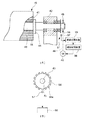
さらに、原反フィルム15に第4の駆動モータ40を連携し、原反フィルム15に対して直接的に所定方向の回転力を与え、帯状フィルム16を所定速度で送出すようにしている。すなわち、図2に示すように、原反フィルム15は、紙管41の周囲に帯状フィルム16を多数回巻き付けることにより構成されているので、その紙管41を、軸受け42に片持ち支持される回転体たる回転軸43に挿入固定し、回転軸43と一体化する。そして、原反フィルム15は回転軸43に設けられたストッパ44により両側から挟持・固定される。
【0029】
この回転軸43の一端にはスプロケット45が固着され、このスプロケット45に掛け渡された動力伝達チェーン46を介して第4の駆動モータ40の回転力を回転軸43に伝達するようにしている。これにより、第4の駆動モータ40が回転すると、回転軸43ひいては原反フィルム15が回転するようになる。そして、この第4の駆動モータ40は、上記した速度制御装置38からの制御信号に基づいて回転駆動するようになっている。
【0030】
なお、第4の駆動モータ40と回転軸43とは、上記した如く動力伝達チェーンを介して接続するのではなく、駆動モータの出力軸を回転軸に直結或いはギヤ等を介して連結するようにしてもよい。
【0031】
上記のように構成したため、第4の駆動モータ40を回転させると、回転軸43ひいては原反フィルム15が所定速度で回転するため、それにともない帯状フィルム16が連続して送出される。そして、第4の駆動モータ40と原反フィルム15とは連動しているため、第4の駆動モータ40が増減速すると、原反フィルム15の回転速度も増減速する。
【0032】
従って、ある速度で回転駆動(高速回転)しているときに、急に第4の駆動モータ40を停止したり、或いは減速したりしたとしても、従来のように原反フィルム15が慣性力により高速回転を続けることはなく、そのまま停止或いは減速するため、第4の駆動モータ40が制動装置の機能も発揮するので従来のような大型な制動装置は不要となる。さらに、第4の駆動モータ40の回転速度を正確に制御することにより、原反フィルム15の回転速度の制御を行うことができ、帯状フィルム16の送出し速度を係る第4の駆動モータ40を制御することにより調整できる。なお、そのようにして送出された帯状フィルム16は、第2の駆動モータ33により回転駆動する補助ローラ28,センターシーラ29からの引っ張り力により、包装機側に所定速度で供給されることになる。
【0033】
ところで、上記構成により原反フィルム15に直接回転力を与えることにより帯状フィルム16は連続して送出されるが、この送出しにともない原反フィルム15の原反フィルム径が徐々に小さくなる。よって、仮に第4の駆動モータ40の回転速度を一定にすると、徐々に帯状フィルム16の送出し速度は遅くなり、横ピロー包装装置の各部の駆動制御の基準となる帯状フィルム16の移動速度が一定にならなくなる。従って、帯状フィルム16を一定速度で製袋器18(包装装置)側に送るためには、原反フィルム径が小さくなるにつれて回転速度を増加していく必要がある。そこで、係る回転速度を徐々に増加していく制御を速度制御装置38で行うようにしている。
【0034】
そして、具体的な制御としては、帯状フィルムを所定速度で移動させ供給させていくと、原反フィルム径が一定の比率で徐々に減少していくため(帯状フィルムは一定速度で包装機側に供給されるので、作業開始からの経過時間により原反フィルム径の減少の程度は求められる)、その減少の程度に合わせて予め定められた作業開始からの経過時間に伴う速度のマップ,テーブルを作成しておき、係るマップ等を参照して第4の駆動モータの速度を増速させていくような制御を行える。
【0035】
また、原反フィルム15の回転に伴う帯状フィルムの送出し速度と、補助ローラ28等の引き出しに伴う帯状フィルム引き出し速度とが等しければ、第2,第4の駆動モータ33,40にはさほど負荷がかからず、所定の電流を供給するだけで所望の回転速度が得られるが、両者の速度が変わると、一方の駆動モータ(回転速度が遅い方)が他方の駆動モータに対して負荷・制動力をかけることになるので、他方の駆動モータを所定速度に回転させるためには通常の供給電流以上の電流を供給する必要がある。また、逆に一方の駆動モータ側では、所定の電流を供給すると、他方の駆動モータから回転力を付与されるため、通常で得られる回転速度以上の速度で回転する。したがって、係る電流の変化(目標値(通常値)からの偏差)や、回転速度の変化(目標値(通常値)からの偏差)を監視し、それらが0(上記引き出し速度と送出し速度とを等しくする)または、所定の値(上記引き出し速度と送出し速度とに一定の差をもたせる)になるように各駆動モータに対してフィードバック制御することもできる。さらには、帯状フィルムの移動速度や移動距離を監視し、それが目標値と一致するように各駆動モータに対してフィードバック制御するようにしても良く、種々の制御方式がとれる。
【0036】
なお、上記した第1,第3の駆動モータに対する速度制御もこの速度制御装置38で行うが、係る制御は従来公知のものであるので、具体的に処理フローは省略する。
【0037】
ところで、上記した制御を行うためには、運転開始当初の原反フィルム径を、速度制御装置38が知っている必要がある。そこで本発明では、係る径を検出するための原反フィルム径検出装置を設けた。
【0038】
この原反フィルム径検出装置は、原反フィルム15の回転角度を計測する回転角計測装置51と、繰り出された帯状フィルム16の移動距離を計測する距離計測装置53と、各計測装置51,53の出力から原反フィルム径を算出する演算処理装置55とから構成される。なお、実際には演算処理装置55と上記速度制御装置38は、CPUにより実行されるため、同一装置内に組み込まれる。
【0039】
まず、回転角計測装置51は、本実施例では電磁式のパルスエンコーダを用いている。すなわち図2に示すように回転軸43の端部近傍に一体的にパルス板56を固着して、回転軸43の回転に伴い一体に回転するようにし、さらにこのパルス板56の外周部にはその周側に沿って一定のピッチをあけて多数の突起56aが径方向に突出形成されている。そして、これらの各突起56aにはその先端部に磁性材が塗布されている。
【0040】
一方、そのパルス板56の外周側には各突起56aと微小な隙間をあけて磁力感知器57が機枠等の固定系に支持される。これにより、磁力感知器57の前を突起56aが通過する都度検出信号が出力されるので、回転軸43(原反フィルム15)の回転にともない回転角計測装置51(磁力感知器57)からパルス信号が出力され、演算処理装置55に与えられる。そして、突起56aの配置間隔(角度)は既知であるので、隣接する突起56a間の角度をθ0 とし、出力されたパルス数をnとすると、求める回転角θは、
θ=n×θ0 …(1)
により算出できる。
【0041】
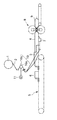
また、距離計測装置53は、図3に示すように、帯状フィルム16を挟んで対向配置された幅広の受けローラ53aと、幅の狭い回転ローラ53bと、その回転ローラ53bに取り付けられたエンコーダ53cとから構成される。そして、受けローラ53aは、帯状フィルム16の幅よりも広くなりその全面と接触するようになっているとともに、フリー状態で図示省略の軸受けに支持されて回転自在となっている。一方、回転ローラ53bは、受けローラ53a側に付勢され、やはりフリー状態で図示省略の軸受けに支持されて回転自在となっている。 これにより、受けローラ53aと回転ローラ53bとは、帯状フィルム16に対し所定の圧力で挟圧することになり、帯状フィルム16の移動にともない、受けローラ53a並びに回転ローラ53bは回転する。
【0042】
そして、その回転ローラ53bの回転軸にエンコーダ53cを取り付けているため(エンコーダの具体的な構成は、例えば上記した回転角計測装置51におけるエンコーダと同様のものを用いることができる)、回転ローラ53bの回転にともない、エンコーダ53cよりパルス信号が出力される。そして回転ローラ53bの円周は既知であり、帯状フィルム16の移動距離と回転ローラ53bの円周面の移動距離は等しいので、その回転ローラ53bが単位角度(隣接するパルス間の角度)回転した時の帯状フィルムの移動距離(基準移動距離T0 )は一義的に決まる。従って、エンコーダから出力されるパルス(単位角度毎に1パルスずつ出力される)をカウントして、パルス数Nを計数したなら、その時の移動距離Tは、
T=N×T0 …(2)
により求められる。
【0043】
そして演算処理装置55では、単位時間あたりに与えられた移動距離Tと回転角度θから、以下の演算処理を行い、開始時の原反フィルム径R0 を求める。
【0044】
R0 =T*(360/θ) …(3)
そして、このようにして算出した径R0 を速度制御装置38に転送し、速度制御装置38では、与えられた原反フィルム径データを運転開始時の原反フィルム径として初期設定し、以後、上記した所定の制御を行う。
【0045】
次に、上記した実施例に基づいて、その作用を説明しつつ本発明に係る原反送出し方法の一実施例について説明する。まず、フィルムのカット寸法,被包装物の高さ・長さ,単位時間あたりの製造個数等の所定の可変データを速度制御装置38に入力する。そして、上記カット寸法と単位時間あたりの製造個数から帯状フィルム16の移動速度(目標値)を求める。
【0046】
なお、上記各データの入力は、ピロー包装装置全体の駆動制御のために必要なもので、原反フィルムの送出し方法のためには、少なくともフィルムのカット寸法と単位時間あたりの製造個数があればよい。また、係るデータを入力せずに、帯状フィルム16の移動速度(目標値)を直接入力するようにしてもよい。
【0047】
次に、速度制御装置38からの制御命令に従い、第2,第4の駆動モータ33,40をそれぞれ所定の回転速度で一定量回転させ、その後停止させる。この時、第2の駆動モータ33の回転にともなう帯状フィルム16の引き出し速度の方が、第4の駆動モータ40の回転にともなう原反フィルム15からの帯状フィルムの送出し速度よりも早くなるように設定する。これにより、実際の帯状フィルムの移動速度は、補助ローラ28,センターシーラ29等ですべりが発生し、速度の遅い第4の駆動モータ40に基づく帯状フィルムの送出し速度になり、帯状フィルムは弛むことなく移動する。
【0048】
この移動時に、距離計測装置53の両ローラ53a,53bも追従して回転し、それにともない所定のパルス(パルス数N)が出力され、また原反フィルム15の回転にともない回転角計測装置51のパルス板56が回転しそれにともない所定のパルス(パルス数n)が出力される。
【0049】
そして、演算処理装置55では、与えられたn,Nに基づいて、上記した式(1),(2)を実行後、式(3)を実行し、その原反フィルム径R0 を算出し、速度制御装置38に転送する。これにより、本発明の要部である原反フィルム径の算出処理が終了する。なお、この算出時に帯状フィルムを移動させるために駆動させる第2,第4の駆動モータ33,40の駆動タイミング(上記一定量の回転)は、たとえば一定時間でも良く、或いはいずれかのパス数n及びまたはNが予め設定したしきい値を越えた時でも良く任意の値を設定できる。そしてしきい値処理する場合には、n,Nの両者を同一のしきい値と比較しても良く、或いはそれぞれに適したしきい値を設定しても良い。また、nまたはNの一方のみを予め比較対象とし、その値が一定のしきい値を越えた時(Nであれば一定距離だけ帯状フィルムが引き出された時)まで駆動するようにしても良く、任意の値を設定できる。
【0050】
そして上記移動速度(目標値)から補助ローラ28,センターシーラ29の回転速度、すなわち、それを駆動するための第2の駆動モータ33の回転速度を求める。さらに、速度制御装置38は、初期設定された管径R0 と移動速度(目標値)に基づいて第4の駆動モータ40の運転開始当初の回転速度を算出する。そして、各部の位置合わせ(初期設定)が終了したならば、第2の駆動モータ33を、上記求めた回転速度で等速回転駆動させる。また、帯状フィルム16が移動速度(目標値)で搬送されているとして第1,第3の駆動モータ27,35も所定のタイミングで増減速駆動する。さらに、第4の駆動モータ40も上記算出結果に基づいて回転させる(移動速度よりも若干遅くなるような速度に設定する)。これにより、引出された帯状フィルムが製袋器18までの間で弛むことがなくなる。
【0051】
そして、第4の駆動モータ40が回転駆動すると、それにともない原反フィルム15も所定速度で回転し、原反フィルム15から帯状フィルム16が送出される。また、これと同時に第2の駆動モータ33が等速回転してそれに連携する補助ローラ28等が等速回転するため、上記送出された帯状フィルム16が等速度で製袋器18を通って筒状フィルム19に製袋されながら内部に被包装物20が供給され、そのままさらに前進することによりセンターシーラ29にてフィルム重合端部位がシールされ、エンドシーラ30で横方向にシール・カットされて包装体34が製造される。
【0052】
またこの運転中の帯状フィルム16の送出し速度は、第4の駆動モータ40を増減速することによりそれに追従するように制御される。よって、上記した速度制御装置38により、原反フィルム15の巻径が小さくなるのに応じて第4の駆動モータ40の回転速度を増加させることにより、一定速度で帯状フィルム16を送出す。しかも、係る速度制御は、リアルタイムで常時行われているため、スムーズに(段差無く)第4の駆動モータ40の回転速度を変動させることができるので、帯状フィルム16の移動速度は、目標値付近でほぼ一定値が保たれる。
【0053】
このように本実施例では、運転開始当初に原反フィルム径を検出するため、開始時の第4の駆動モータ40の回転速度を係る径に応じて最適な値に設定できるので、開始時から第4の駆動モータ40による原反フィルムからの帯状フィルムの送出し量と、第2の駆動モータ33による帯状フィルムの引き出し量(ともに単位時間あたり)がほぼ等しい所定の関係に維持され、帯状フィルム16は最初から所定のテンショが過不足なく加わる。
【0054】
よって、一方のモータに過電流が流れたり、帯状フィルムに必要以上のテンションが加わったりすることがなく、所望の状態で包装処理が行える。そして、開始する都度原反フィルム径の検出が行われるため、終業時,メンテナンス時その他の理由により包装装置を停止し、その後、再運転する場合や、使用途中の原反フィルムを装着する場合など、原反フィルム径が未使用時のものから小さくなっているように、正確な径が不明な場合でも、確実に所望の状態で装置の稼働を行える。
【0055】
なお、本実施例では、制動装置のような大型な設備が不要となり、原反フィルム15から製袋器18までの間には、プーリ17のように嵩の張らない部材のみが存在するので、実装された包装装置全体の嵩を低くし、小型化を図ることができる。
【0056】
また、上記した実施例では、第1,第3の駆動モータ27,35を夫々、所定のタイミングで増減速するようにしたが、本発明はこれに限ることなく、第1の駆動モータ27は等速回転するものでもよい。すなわち、実施例では被包装物20が製包機18に供給される際にはそれと接触する筒状フィルム19と同速度で移動させるようにしたが、被包装物20が固く、筒状フィルム19との速度差による接触抵抗によってもくずれたりしないような場合には、上記のように第1の駆動モータ27を等速回転させて被包装物供給装置22の搬送速度を一定にすることにより、制御系を簡易にすることができる。
【0057】
なお原反フィルムの回転角度を検出する手段としては、上記した実施例に限ることなく、例えば第4の駆動モータ40の出力軸の回転角度を検出し、それに基づいて換算してもよく、ようは直接または間接的に回転角度が求められればよい。
【0058】
なお上記した実施例では、実装する製袋充填包装機として上記した実施例では横ピロー包装装置に適用した例について説明したが、縦ピロー包装装置,横三方包装装置や四方包装装置等使用する包装フィルムが原反フィルムから連続して引出されるものであれば種々の製袋充填包装機に適用することができる。
【0059】
【発明の効果】
以上のように、本発明では、ユーザーは使用する原反フィルムを装着するだけで、自動的に装着した原反フィルムの現在の径を計測することができる。その計測した原反フィルム径のデータに基づいて稼働する本発明に係る原反フィルムの送出し方法及び装置では、運転開始時の原反フィルム径に適した駆動モータの回転速度を設定し、その回転速度で駆動モータを稼働できるので、運転開始当初から帯状フィルムを所望の目標移動速度で送出すことができ、帯状フィルムや装置に過負荷を与えることがない。よって、その後に行われる原反フィルム径の減少にともなう駆動モータに対する回転速度の増減速制御でも、係る回転速度が急激に変動することがなく、スムーズな運転・制御が行える。
【0060】
そして、本発明でも運転開始後の制御においては、原反フィルム側で帯状フィルムの送出しを制御できるので、駆動モータを増減速するとそれに追従して原反フィルムの回転速度も増減速し、駆動モータを停止すると原反フィルムの回転も停止させることができる。よって、従来のように慣性力により原反フィルムが回転し続けることがなく、原反フィルムに対する大掛かりな制動装置が不要となる。
【0061】
そして、帯状フィルムの送出しに伴う原反フィルム径の減少に合わせて駆動モータの回転を所定の比率で徐々に増速していくと、帯状フィルムを等速度で送出すことができる。
【図面の簡単な説明】
【図1】本発明に係る製袋充填包装機における原反送出し装置の一実施例を示す図である。
【図2】本実施例の要部である原反フィルム付近を示す一部拡大断面図である。
【図3】本実施例の要部である距離計測装置を示す一部拡大断面図である。
【図4】従来技術を示す図である。
【符号の説明】
15 原反フィルム
16 帯状フィルム
28 補助ローラ(供給する手段)
29 センターシーラ(供給する手段)
33 第2の駆動モータ(供給する手段)
38 速度制御装置
40 第4の駆動モータ(駆動モータ)
51 回転角計測装置
53 距離計測装置
55 演算処理装置[0001]
[Industrial application fields]
The present invention relates to a raw film feeding device and a feeding method in a bag filling and packaging machine, a bag making filling and packaging machine, and a packaging method.
[0002]
BACKGROUND OF THE INVENTION
Conventionally, in a bag making and filling machine such as a horizontal pillow wrapping machine, for example, as shown in FIG. 4, the film is drawn out as a continuous band film 2 from a
[0003]
Then, the belt-like film 2 is sent out from the
[0004]
For the drive control of each of the above parts, for example, the system disclosed in Japanese Patent Laid-Open No. 63-281911 is used. That is, the other two drive systems (the drive system of the
[0005]
By the way, when the belt-like film 2 is sandwiched and pulled out by the
[0006]
Therefore, a braking device for braking the rotation is provided on the
[0007]
However, if the braking force of the braking device is too strong, the belt-like film 2 slips at the
[0008]
However, in such an apparatus, the diameter of the original film that can be detected by the photoelectric sensor is stepwise, and therefore cannot accurately follow the tube diameter that sequentially changes as the belt-shaped film is drawn. As a result, it is optimal to focus on the interval from the detection of the outer circumference of the original film with a certain photoelectric sensor (calculation of the tube diameter) to the detection of the outer circumference of the original film with the photoelectric sensor existing inside the next one. The braking force cannot be generated, resulting in excess or deficiency.
[0009]
Furthermore, the braking device is installed around the
[0010]
Therefore, in order to solve such a problem, the present applicant can reduce the size of the entire packaging apparatus that is mounted without requiring a large-scale braking device, and it is possible to follow the increase or decrease in the winding diameter of the original film (follow-up). A material sending device in a bag-filling and packaging machine that can be pulled out at a predetermined speed while applying a certain tension (tension) from the original film to the belt-like film, and that can be easily controlled. It was created and applied for in Japanese Patent Application No. 6-52687.
[0011]
Briefly explaining the invention of the prior application, a drive motor capable of increasing / decelerating control is connected to the rotating body on which the original film is mounted, and the original film is moved at a predetermined speed in a predetermined direction by the rotational force of the drive motor. Try to rotate. As a result, the rotational speed of the original film also increases / decreases following the increase / decrease of the drive motor. When the drive motor is stopped, the rotation of the original film also stops, so that the drive motor also functions as a braking device. And according to the control command from a speed control apparatus, the rotational speed of the drive motor was increased according to the reduction | decrease of a raw film diameter, and the moving speed of the strip | belt-shaped film was made constant.
[0012]
In this speed control, the driving state is monitored (for example, the moving speed of the belt-like film is detected), and when the feedback control is performed on the driving motor so that the monitoring result becomes a desired state, the driving motor is once If the rotation speed becomes suitable for the desired moving speed of the belt-like film, smooth control can be performed thereafter, and the speed of the drive motor can be gradually increased. If the speed is too fast, the strip film will be sent more than necessary and loosen. Therefore, the rotational speed of the drive motor is usually slowed down. However, if the speed is too slow, excessive stress is applied to the belt-like film, which may extend or break. Further, when the belt-like film is stiff, there is a risk that the drawing means such as the center sealer will be overloaded and damaged. Therefore, in order to actually perform the above-described control, it is necessary to grasp the raw film diameter at the time of starting, obtain the rotation speed of the drive motor suitable for the diameter, and operate. And, when using an unused raw film, the approximate original film diameter is known in advance, so it is only necessary to initially set and input the diameter, but the original raw film is being used. When using, the user needs to measure and input the raw film diameter, which is complicated.
[0013]
The present invention has been made in view of the above-described background, and the object of the present invention is to solve the above-described problems and automatically start the original film without using the original film diameter. An object of the present invention is to provide a raw film feeding apparatus and feeding method, a bag making filling and packaging machine, and a packaging method in a bag making filling and packaging machine that measures the diameter and is accurate and smooth.
[0014]
[Means for Solving the Problems]
In order to achieve the above-described object, the method of feeding the original fabric in the bag-filling and packaging machine according to the present invention continuously applies the rotational force of a drive motor capable of acceleration / deceleration control to the original fabric film. In a bag filling and packaging machine that wraps a package to be conveyed at predetermined intervals using a belt-shaped film that is sent out and manufactures a package by sealing and / or cutting a predetermined portion of the film A method for sending a film, wherein at the start of operation, the belt-like film is sent out by a predetermined amount from the raw film, then stopped, and the movement distance of the belt-like film when the predetermined amount is sent, Measure the rotation angle of the original film, calculate the original film diameter based on the measured moving distance and the rotation angle, and calculate the original film diameter. Accordingly, the rotational speed of the drive motor at the beginning of the operation for the belt-shaped film to be delivered to the target moving speed is determined, and when the operation is resumed by releasing the stop, the determined rotational speed is The drive motor is operated, and then the rotation speed of the drive motor is increased or decreased to change the rotation speed of the original film, and the belt-shaped film is fed in accordance with the change of the original film diameter. The speed was controlled.
[0015]
And as an apparatus for carrying out the above method, the belt-like film continuously fed from the anti-film is wrapped with an article to be packaged conveyed at predetermined intervals, and a predetermined part of the film is sealed and Alternatively, a raw film feeding device provided in a bag-filling and packaging machine for manufacturing a package by cutting, and a drive motor capable of increasing / decelerating control for applying a rotational force to a rotating body on which the original film is mounted A distance measuring device that measures the moving distance of the belt-like film that is sent out by the rotation of the original film, a rotational angle measuring device that measures the rotational angle of the original film, the distance measuring device, and the rotational angle measurement An arithmetic processing unit that receives movement distance data and rotation angle data respectively measured by the apparatus and calculates the raw film diameter based on the output, and its calculation Based on the raw film diameter calculated by the physical device, the rotational speed of the drive motor at the beginning of operation is determined, and the delivery is performed in accordance with the decrease in the tube diameter accompanying the delivery of the strip film. A speed control device for controlling the speed of the drive motor so as to set the feeding speed of the belt-like film to a predetermined speed, and means for supplying the fed belt-like film to the bag-filling and packaging machine side, and starting the operation The process of determining the rotational speed of the drive motor that is initially performed is that the drive motor is rotated to send the belt-like film from the original film by a predetermined amount, and then stopped, and when the predetermined amount is sent, The arithmetic processing unit calculates the movement distance of the belt-shaped film obtained by the distance measuring device and the rotation angle of the original film obtained by the rotation angle measuring device. And so, the speed control apparatus, when restarting the operation to release the stop, and configured to run the drive motor at a rotational speed which the processor has calculated determined.
[0016]
In addition, the packaging method according to the present invention continuously feeds from the original film by applying a rotational force of a drive motor capable of acceleration / deceleration control to the original film, and uses the fed strip-shaped film, It is a packaging method in a bag-filling and packaging machine that performs a process of wrapping a package to be transported at predetermined intervals, seals and / or cuts a predetermined part of a film that wraps the package, and manufactures a package. At the start of operation, a predetermined amount of the belt-like film is sent out from the raw film, and then stopped, and the movement distance of the belt-like film and the rotation angle of the raw film when the predetermined amount is sent are measured. Then, the original film diameter is calculated based on the measured moving distance and rotation angle, and the belt-shaped film to be sent out is calculated based on the calculated original film diameter. Determining the rotational speed of the drive motor at the beginning of operation for reaching the target moving speed, when releasing the stop and restarting the operation, the drive motor is operated at the determined rotational speed, and then By increasing / decreasing the rotational speed of the drive motor, the rotational speed of the original film is changed, and the feeding speed of the belt-like film is controlled in accordance with the change of the original film diameter. The film was sent out.
And the bag making filling and packaging machine according to the present invention suitable for carrying out the method is to apply a rotational force to the anti-film, and to continuously feed the belt-like film from the original film, Means for wrapping a package to be transported at predetermined intervals using a belt-shaped film fed by an original fabric feed device, and means for sealing and / or cutting a predetermined portion of the film that wraps the package The raw film feeding device includes a drive motor capable of acceleration / deceleration control that applies a rotational force to a rotating body on which the raw film is mounted, and movement of the belt-shaped film fed by the rotation of the raw film A distance measuring device for measuring the distance, a rotation angle measuring device for measuring the rotation angle of the original film, and the transfer measured by the distance measuring device and the rotation angle measuring device, respectively. An arithmetic processing device that receives the distance data and the rotation angle data and calculates the raw film diameter based on the output, and the drive at the beginning of operation based on the raw film diameter calculated by the arithmetic processing device A speed for determining the rotational speed of the motor and controlling the speed of the drive motor so that the feeding speed of the belt-like film to be fed becomes a predetermined speed in accordance with the decrease in the tube diameter accompanying the feeding of the belt-like film. A control device and means for supplying the fed belt-like film to the bag making and filling and packaging machine side, and the rotational speed determination process of the drive motor performed at the beginning of the operation is performed by rotating the drive motor. When the belt-like film is sent out from the original film by a predetermined amount and then stopped, the distance measuring device obtained when the predetermined amount is sent out. The arithmetic processing unit calculates based on the moving distance of the belt-shaped film and the rotation angle of the original film obtained by the rotation angle measuring device, and the speed control device releases the stop and restarts the operation. In this case, the drive motor is operated at the rotational speed calculated and determined by the arithmetic processing unit.
[0017]
[Action]
First, prior to the start of operation, the driving motor is driven by a predetermined amount (time, film moving distance, rotation angle of the original film, etc.), the original film is rotated, and the belt-like film is sent out. At this time, the total moving distance of the belt-like film is measured by the distance measuring device, and the rotation angle of the original film is measured by the rotation angle measuring device.
[0018]
The movement distance measured by the distance measuring device is equal to the length of the arc of the fan whose central angle is the rotation angle measured by the rotation angle measuring device. Therefore, the arc length (corresponding to the circumference) when the center angle of the fan is 360 degrees, that is, a circle, can be subjected to predetermined four arithmetic operations based on the two measured data. The diameter from the circumference can be easily obtained by four arithmetic operations. In this way, the raw film diameter is calculated.
[0019]
The rotational speed of the original film, that is, the rotational speed of the drive motor is calculated from the raw film diameter thus obtained and the target moving speed of the strip film, and the drive motor is operated at the determined rotational speed. . Then, the rotational force is transmitted to the original film, and the original film is rotated at a predetermined speed. Along with this, the belt-like film wound around the original film is sent out at a predetermined speed, and this speed becomes substantially equal to the target speed. As a result, the belt-like film can be sent out at the target speed or a speed close to the target speed from the beginning of operation, and a smooth start can be performed without overloading the belt-like film and each device.
[0020]
Thereafter, the feeding speed of the belt-like film is controlled so as to follow the speed by increasing / decreasing the driving motor. Therefore, the belt-like film is sent out at a constant speed by increasing the rotational speed of the drive motor as the roll diameter of the original film is reduced by the control device. In addition, since the rotation of the original film follows the rotation of the drive motor in this way, when the drive motor is decelerated or stopped, the rotation of the original film also decelerates / stops according to the change, Since it does not continue to rotate due to the inertial force, a conventional braking device is also unnecessary. And the strip | belt-shaped film sent out as mentioned above is supplied to the predetermined position of a bag making filling packaging machine at a predetermined | prescribed speed | rate by the supply means, and is used as a packaging film.
[0021]
【Example】
Hereinafter, preferred embodiments of the present invention will be described in detail with reference to the accompanying drawings. FIG. 1 shows an embodiment of a raw film feeding apparatus according to the present invention and a bag making filling and packaging machine (pillow packaging apparatus) on which the apparatus is mounted. As shown in the figure, the belt-
[0022]
On the carry-in side (upstream side) of the
[0023]
Further, an
[0024]
The
[0025]
The
[0026]
The
[0027]
Further, the
[0028]
Further, the
[0029]
A
[0030]
The
[0031]
Since it comprised as mentioned above, when the
[0032]
Therefore, even if the
[0033]
By the way, the belt-
[0034]
As specific control, when the belt-like film is moved and supplied at a predetermined speed, the raw film diameter gradually decreases at a constant rate (the belt-like film is moved to the packaging machine side at a constant speed). The degree of decrease in the raw film diameter is determined by the elapsed time from the start of work), and a map and table of speeds with the elapsed time from the start of work set in advance according to the degree of decrease The control can be performed so as to increase the speed of the fourth drive motor with reference to such a map.
[0035]
Further, if the feeding speed of the belt-like film accompanying the rotation of the
[0036]
Although the speed control for the first and third drive motors is also performed by the
[0037]
By the way, in order to perform the above-described control, the
[0038]
This raw film diameter detection device includes a rotation
[0039]
First, the rotation
[0040]
On the other hand, a
θ = n × θ0 (1)
Can be calculated.
[0041]
Further, as shown in FIG. 3, the
[0042]
Since the
T = N × T0 (2)
Is required.
[0043]
Then, the
[0044]
R0 = T * (360 / .theta.) (3)
Then, the diameter R0 calculated in this way is transferred to the
[0045]
Next, on the basis of the above-described embodiment, an embodiment of the raw fabric sending method according to the present invention will be described while explaining the operation thereof. First, predetermined variable data such as a film cut dimension, a height / length of an object to be packaged, and a production number per unit time are input to the
[0046]
Note that the input of the above data is necessary for the drive control of the entire pillow packaging apparatus. For the method of feeding the raw film, at least the cut size of the film and the number of products manufactured per unit time should be included. That's fine. Alternatively, the moving speed (target value) of the
[0047]
Next, according to a control command from the
[0048]
During this movement, both
[0049]
And in the
[0050]
Then, the rotational speed of the
[0051]
When the
[0052]
Further, the feeding speed of the belt-
[0053]
Thus, in this embodiment, since the raw film diameter is detected at the beginning of the operation, the rotation speed of the
[0054]
Therefore, an overcurrent does not flow through one of the motors, and an unnecessary tension is not applied to the strip film, and the packaging process can be performed in a desired state. And since the raw film diameter is detected every time it starts, the packaging equipment is stopped at the end of work, maintenance, or for other reasons, and then restarted, or the original film is being used. Even when the exact diameter is unknown so that the raw film diameter is smaller than that when not used, the apparatus can be reliably operated in a desired state.
[0055]
In the present embodiment, a large facility such as a braking device is not necessary, and only a non-bulk member such as the
[0056]
In the above-described embodiment, the first and
[0057]
The means for detecting the rotation angle of the raw film is not limited to the above-described embodiment, and for example, the rotation angle of the output shaft of the
[0058]
In the above-described embodiment, the example in which the bag-filling and packaging machine to be mounted is applied to the horizontal pillow packaging apparatus in the above-described embodiment has been described. However, the vertical pillow packaging apparatus, the horizontal three-way packaging apparatus, the four-way packaging apparatus, etc. As long as the film is continuously drawn from the raw film, it can be applied to various bag-filling and packaging machines.
[0059]
【The invention's effect】
As described above, according to the present invention, the user can measure the current diameter of the automatically loaded original film only by attaching the original film to be used. In the raw film delivery method and apparatus according to the present invention that operates based on the measured raw film diameter data, the rotational speed of the drive motor suitable for the raw film diameter at the start of operation is set, and Since the drive motor can be operated at the rotational speed, the belt-like film can be sent out at a desired target moving speed from the beginning of operation, and the belt-like film and the apparatus are not overloaded. Therefore, even in the subsequent increase / decrease control of the rotation speed of the drive motor with the decrease in the raw film diameter, the rotation speed does not fluctuate rapidly, and smooth operation / control can be performed.
[0060]
In the present invention, since the feeding of the belt-like film can be controlled on the original film side in the control after the start of operation, when the drive motor is increased / decreased, the rotation speed of the original film increases / decreases accordingly. When the motor is stopped, the rotation of the original film can also be stopped. Therefore, the original film does not continue to rotate due to the inertial force as in the prior art, and a large braking device for the original film becomes unnecessary.
[0061]
Then, when the rotation of the drive motor is gradually increased at a predetermined ratio in accordance with the decrease in the raw film diameter accompanying the feeding of the belt-like film, the belt-like film can be fed at a constant speed.
[Brief description of the drawings]
FIG. 1 is a view showing an embodiment of an original fabric feeding apparatus in a bag making filling and packaging machine according to the present invention.
FIG. 2 is a partially enlarged cross-sectional view showing the vicinity of a raw film which is a main part of the present example.
FIG. 3 is a partially enlarged cross-sectional view showing a distance measuring device which is a main part of the embodiment.
FIG. 4 is a diagram showing a conventional technique.
[Explanation of symbols]
15 Original film
16 Strip film
28 Auxiliary roller (supplying means)
29 Center sealer (means to supply)
33 Second drive motor (supplying means)
38 Speed control device
40 Fourth drive motor (drive motor)
51 Rotation angle measuring device
53 Distance measuring device
55 Arithmetic processing unit
Claims (4)
運転開始時に、前記原反フィルムから前記帯状フィルムを所定量だけ送出し、その後停止させ、その所定量だけ送出された際の前記帯状フィルムの移動距離と、前記原反フィルムの回転角度をそれぞれ計測し、
その計測された移動距離と回転角度に基づいて前記原反フィルム径を算出し、
その算出した前記原反フィルム径に基づいて、送出される帯状フィルムが目標移動速度になるための運転開始当初の前記駆動モータの回転速度を決定し、
前記停止を解除して運転を再開する際に、当該決定した回転速度で前記駆動モータを稼働するようにし、
その後、前記駆動モータの回転速度を増加または減少させることにより、前記原反フィルムの回転速度を変化させ、前記原反フィルム径の変化に応じて前記帯状フィルムの送出し速度を制御するようにした製袋充填包装機における原反送出し方法。By wrapping the material to be packaged at predetermined intervals using the belt-like film continuously fed from the original film by applying the rotational force of the drive motor capable of increasing / decelerating control to the original film, A method for feeding an original film in a bag-filling and packaging machine for producing a package by sealing and / or cutting a predetermined part of a film,
At the start of operation, a predetermined amount of the belt-like film is sent out from the raw film, and then stopped, and the movement distance of the belt-like film and the rotation angle of the raw film when the predetermined amount is sent are measured. And
Calculate the original film diameter based on the measured travel distance and rotation angle,
Based on the calculated raw film diameter, determine the rotational speed of the drive motor at the beginning of operation for the belt-shaped film to be delivered to the target moving speed,
When releasing the stop and restarting operation, the drive motor is operated at the determined rotational speed,
Thereafter, by increasing or decreasing the rotation speed of the drive motor, the rotation speed of the original film is changed, and the feeding speed of the belt-like film is controlled according to the change of the original film diameter. Raw material feeding method in bag making filling and packaging machine.
前記原反フィルムを装着する回転体に対し回転力を与える増減速制御可能な駆動モータと、前記原反フィルムの回転により送出される帯状フィルムの移動距離を計測する距離計測装置と、前記原反フィルムの回転角度を計測する回転角計測装置と、前記距離計測装置と前記回転角計測装置でそれぞれ計測された移動距離データと回転角度データを受け取るとともに、その出力に基づいて原反フィルム径を算出する演算処理装置と、
その演算処理装置により算出された前記原反フィルム径に基づいて、運転開始当初の前記駆動モータの回転速度を決定するとともに、前記帯状フィルムの送出しにともなう管径の減少に応じて、前記送出される帯状フィルムの送出し速度を所定速度にすべく前記駆動モータの速度を制御する速度制御装置と、前記送出された帯状フィルムを前記製袋充填包装機側へ供給する手段とを備え、
前記運転開始当初に行なう前記駆動モータの回転速度の決定処理は、前記駆動モータを回転させて前記原反フィルムから前記帯状フィルムを所定量だけ送出し、その後停止させ、その所定量だけ送出された際に前記距離計測装置が求めた前記帯状フィルムの移動距離と、前記回転角計測装置で求めた前記原反フィルムの回転角度に基づき前記演算処理装置が算出するようにし、
前記速度制御装置は、前記停止を解除して運転を再開する際に、前記演算処理装置が算出し決定した回転速度で前記駆動モータを稼働するようにしてなることを特徴とする製袋充填包装機における原反フィルム送出し装置。Bag-making filling that wraps an article to be packaged that is conveyed at predetermined intervals using a belt-like film continuously fed from a raw film, and seals and / or cuts a predetermined portion of the film to produce a package. An apparatus for feeding a raw film provided in a packaging machine,
A drive motor capable of acceleration / deceleration control that applies a rotational force to a rotating body on which the original film is mounted, a distance measuring device that measures a moving distance of a belt-shaped film sent out by the rotation of the original film, and the original film A rotation angle measurement device that measures the rotation angle of the film, and the distance measurement device and the rotation angle measurement device that receive the movement distance data and the rotation angle data, respectively, and calculates the raw film diameter based on the output. An arithmetic processing unit to
Based on the raw film diameter calculated by the arithmetic processing unit, the rotational speed of the drive motor at the beginning of operation is determined, and the delivery is performed according to the decrease in the tube diameter accompanying the delivery of the belt-like film. A speed control device for controlling the speed of the drive motor so as to set the feeding speed of the belt-like film to be a predetermined speed, and means for supplying the fed belt-like film to the bag making filling and packaging machine side,
The process of determining the rotational speed of the drive motor that is performed at the beginning of the operation is to rotate the drive motor to send the belt-like film from the original film by a predetermined amount, then stop, and send that predetermined amount. The calculation processing device calculates the movement distance of the belt-like film obtained by the distance measurement device and the rotation angle of the raw film obtained by the rotation angle measurement device,
The speed control device operates the drive motor at a rotational speed calculated and determined by the arithmetic processing unit when releasing the stop and restarting operation. Raw film feeding device in the machine.
その送り出された帯状のフィルムを用いて、所定間隔毎に搬送される被包装物を包む処理を行ない、
その被包装物を包み込んだフィルムの所定部位をシール及びまたはカットして包装体を製造する製袋充填包装機における包装方法であり、
運転開始時に、前記原反フィルムから前記帯状フィルムを所定量だけ送出し、その後停止させ、その所定量だけ送出された際の前記帯状フィルムの移動距離と、前記原反フィルムの回転角度をそれぞれ計測し、
その計測された移動距離と回転角度に基づいて前記原反フィルム径を算出し、
その算出した前記原反フィルム径に基づいて、送出される帯状フィルムが目標移動速度になるための運転開始当初の前記駆動モータの回転速度を決定し、
前記停止を解除して運転を再開する際に、当該決定した回転速度で前記駆動モータを稼働させ、
その後、前記駆動モータの回転速度を増加・減少させることにより、前記原反フィルムの回転速度を変化させ、前記原反フィルム径の変化に応じて前記帯状フィルムの送出し速度を制御することにより前記帯状のフィルムの送出しを行なうこと特徴とする包装方法。Sending continuously from the original film by applying the rotational force of the drive motor that can control the speed increase / decrease to the original film,
Using the belt-like film that has been sent out, a process for wrapping a package to be transported at predetermined intervals is performed.
It is a packaging method in a bag making and filling packaging machine that manufactures a package by sealing and / or cutting a predetermined portion of a film that wraps the article to be packaged,
At the start of operation, a predetermined amount of the belt-like film is sent out from the raw film, and then stopped, and the movement distance of the belt-like film and the rotation angle of the raw film when the predetermined amount is sent are measured. And
Calculate the original film diameter based on the measured travel distance and rotation angle,
Based on the calculated raw film diameter, determine the rotational speed of the drive motor at the beginning of operation for the belt-shaped film to be delivered to the target moving speed,
When releasing the stop and restarting the operation, the drive motor is operated at the determined rotational speed,
Thereafter, by increasing / decreasing the rotation speed of the drive motor, the rotation speed of the original film is changed, and the feeding speed of the belt-like film is controlled according to the change of the original film diameter. A packaging method characterized by feeding a belt-like film.
その原反送り出し装置により送り出された帯状のフィルムを用いて、所定間隔毎に搬送される被包装物を包む手段と、
その被包装物を包み込んだフィルムの所定部位をシール及びまたはカットする手段とを備え、
前記原反フィルムの送出し装置は、
前記原反フィルムを装着する回転体に対し回転力を与える増減速制御可能な駆動モータと、前記原反フィルムの回転により送出される帯状フィルムの移動距離を計測する距離計測装置と、前記原反フィルムの回転角度を計測する回転角計測装置と、前記距離計測装置と前記回転角計測装置でそれぞれ計測された移動距離データと回転角度データを受け取るとともに、その出力に基づいて原反フィルム径を算出する演算処理装置と、その演算処理装置により算出された前記原反フィルム径に基づいて、運転開始当初の前記駆動モータの回転速度を決定するとともに、前記帯状フィルムの送出しにともなう管径の減少に応じて、前記送出される帯状フィルムの送出し速度を所定速度にすべく前記駆動モータの速度を制御する速度制御装置と、前記送出された帯状フィルムを前記製袋充填包装機側へ供給する手段とを備え、
前記運転開始当初に行なう前記駆動モータの回転速度の決定処理は、前記駆動モータを回転させて前記原反フィルムから前記帯状フィルムを所定量だけ送出し、その後停止させ、その所定量だけ送出された際に前記距離計測装置が求めた前記帯状フィルムの移動距離と、前記回転角計測装置で求めた前記原反フィルムの回転角度に基づき前記演算処理装置が算出するようにし、
前記速度制御装置は、前記停止を解除して運転を再開する際に、前記演算処理装置が算出し決定した回転速度で前記駆動モータを稼働するようにしてなることを特徴とする製袋充填包装機。An original film sending device that applies a rotational force to the original film, and continuously feeds a belt-like film from the original film;
Means for wrapping an article to be wrapped that is conveyed at predetermined intervals using a belt-like film fed by the raw fabric feeding device;
Means for sealing and / or cutting a predetermined portion of the film enclosing the packaged object,
The raw film delivery device is:
A drive motor capable of acceleration / deceleration control that applies a rotational force to a rotating body on which the original film is mounted, a distance measuring device that measures a moving distance of a belt-shaped film sent out by the rotation of the original film, and the original film A rotation angle measurement device that measures the rotation angle of the film, and the distance measurement device and the rotation angle measurement device that receive the movement distance data and the rotation angle data, respectively, and calculates the raw film diameter based on the output. And a rotational speed of the drive motor at the beginning of operation based on the original film diameter calculated by the arithmetic processing device, and a decrease in the tube diameter accompanying the feeding of the belt-like film And a speed control device for controlling the speed of the drive motor so as to make the delivery speed of the fed belt-like film a predetermined speed, and The filmstrip issued and means for supplying to said bag filling and packaging machine, the
The process of determining the rotational speed of the drive motor that is performed at the beginning of the operation is to rotate the drive motor to send the belt-like film from the original film by a predetermined amount, then stop, and send that predetermined amount. The calculation processing device calculates the movement distance of the belt-like film obtained by the distance measurement device and the rotation angle of the raw film obtained by the rotation angle measurement device,
The speed control device operates the drive motor at a rotational speed calculated and determined by the arithmetic processing unit when releasing the stop and restarting operation. Machine.
Priority Applications (1)
| Application Number | Priority Date | Filing Date | Title |
|---|---|---|---|
| JP11027795A JP3676842B2 (en) | 1995-04-12 | 1995-04-12 | Raw film feeding device and feeding method in bag making filling and packaging machine, bag making filling and packaging machine and packaging method |
Applications Claiming Priority (1)
| Application Number | Priority Date | Filing Date | Title |
|---|---|---|---|
| JP11027795A JP3676842B2 (en) | 1995-04-12 | 1995-04-12 | Raw film feeding device and feeding method in bag making filling and packaging machine, bag making filling and packaging machine and packaging method |
Related Child Applications (1)
| Application Number | Title | Priority Date | Filing Date |
|---|---|---|---|
| JP2004368545A Division JP2005132497A (en) | 2004-12-20 | 2004-12-20 | Bag making packing packer and packaging method |
Publications (2)
| Publication Number | Publication Date |
|---|---|
| JPH08282890A JPH08282890A (en) | 1996-10-29 |
| JP3676842B2 true JP3676842B2 (en) | 2005-07-27 |
Family
ID=14531617
Family Applications (1)
| Application Number | Title | Priority Date | Filing Date |
|---|---|---|---|
| JP11027795A Expired - Lifetime JP3676842B2 (en) | 1995-04-12 | 1995-04-12 | Raw film feeding device and feeding method in bag making filling and packaging machine, bag making filling and packaging machine and packaging method |
Country Status (1)
| Country | Link |
|---|---|
| JP (1) | JP3676842B2 (en) |
Cited By (1)
| Publication number | Priority date | Publication date | Assignee | Title |
|---|---|---|---|---|
| JP2007008558A (en) * | 2005-07-01 | 2007-01-18 | Ishida Co Ltd | Packaging device |
Families Citing this family (2)
| Publication number | Priority date | Publication date | Assignee | Title |
|---|---|---|---|---|
| US5967445A (en) | 1996-09-20 | 1999-10-19 | Kabushiki Kaisha Yuyama Seisakusho | Method of adjusting tension applied to sheet, and device for the same |
| JP5569006B2 (en) * | 2010-01-25 | 2014-08-13 | 株式会社寺岡精工 | Packaging equipment |
-
1995
- 1995-04-12 JP JP11027795A patent/JP3676842B2/en not_active Expired - Lifetime
Cited By (1)
| Publication number | Priority date | Publication date | Assignee | Title |
|---|---|---|---|---|
| JP2007008558A (en) * | 2005-07-01 | 2007-01-18 | Ishida Co Ltd | Packaging device |
Also Published As
| Publication number | Publication date |
|---|---|
| JPH08282890A (en) | 1996-10-29 |
Similar Documents
| Publication | Publication Date | Title |
|---|---|---|
| US5347791A (en) | Computer controlled horizontal wrapper | |
| US4691499A (en) | Method of tensioning a web of packaging material | |
| JPH02180104A (en) | Method and device for packaging | |
| JP2673407B2 (en) | Film feeding control method and apparatus for vertical bag-making filling and packaging machine | |
| JPH07237796A (en) | Method and device for sending out raw fabric on bag forming filling and closing machine for flexible package | |
| JP3676842B2 (en) | Raw film feeding device and feeding method in bag making filling and packaging machine, bag making filling and packaging machine and packaging method | |
| JP3676844B2 (en) | Raw film feeding device and feeding method in bag making filling and packaging machine, bag making filling and packaging machine and packaging method | |
| US6623412B2 (en) | Bag making machine with web tension control and method | |
| JPS62295859A (en) | Intermittent feed device for band-like web | |
| JP2005132633A (en) | Bag manufacturing, filling and packing machine, and packing method | |
| JP2000171235A (en) | Instrument and method for measuring rolled film diameter | |
| JP3688310B2 (en) | Raw material feeding method and apparatus in bag making filling and packaging machine | |
| JP2005132497A (en) | Bag making packing packer and packaging method | |
| JP3872133B2 (en) | Packaging machine | |
| JPH01316253A (en) | Operation control method for rewinding device for belt-shaped rubber sheet | |
| JP3575843B2 (en) | Raw material sending method and apparatus in bag making and filling machine | |
| JP2004345728A (en) | Control device for film paying-out in packer | |
| JP4133087B2 (en) | Packaging system | |
| JPH07285715A (en) | Method and device for feeding rolled web in bag manufacturing, filling and wrapping machine | |
| JP2529037B2 (en) | Stop position control method and device in horizontal bag-making filling and packaging machine | |
| JP3898865B2 (en) | Packaging material feeding control device for vertical bag making filling and packaging machine | |
| JP3245706B2 (en) | Method and apparatus for detecting end of web of packaging machine | |
| JP2022535545A (en) | Feeding unit for feeding plastic film | |
| JPH10119910A (en) | Film transfer device for horizontal bag-making, filling machine | |
| JP2004284686A (en) | Bag manufacturing/filling/packing machine |
Legal Events
| Date | Code | Title | Description |
|---|---|---|---|
| A977 | Report on retrieval |
Free format text: JAPANESE INTERMEDIATE CODE: A971007 Effective date: 20040415 |
|
| A131 | Notification of reasons for refusal |
Free format text: JAPANESE INTERMEDIATE CODE: A131 Effective date: 20040427 |
|
| A521 | Written amendment |
Free format text: JAPANESE INTERMEDIATE CODE: A523 Effective date: 20040628 |
|
| A02 | Decision of refusal |
Free format text: JAPANESE INTERMEDIATE CODE: A02 Effective date: 20041019 |
|
| A521 | Written amendment |
Free format text: JAPANESE INTERMEDIATE CODE: A523 Effective date: 20041220 |
|
| A521 | Written amendment |
Free format text: JAPANESE INTERMEDIATE CODE: A523 Effective date: 20050126 |
|
| A911 | Transfer of reconsideration by examiner before appeal (zenchi) |
Free format text: JAPANESE INTERMEDIATE CODE: A911 Effective date: 20050201 |
|
| TRDD | Decision of grant or rejection written | ||
| A01 | Written decision to grant a patent or to grant a registration (utility model) |
Free format text: JAPANESE INTERMEDIATE CODE: A01 Effective date: 20050405 |
|
| A61 | First payment of annual fees (during grant procedure) |
Free format text: JAPANESE INTERMEDIATE CODE: A61 Effective date: 20050502 |
|
| R150 | Certificate of patent or registration of utility model |
Free format text: JAPANESE INTERMEDIATE CODE: R150 |
|
| FPAY | Renewal fee payment (event date is renewal date of database) |
Free format text: PAYMENT UNTIL: 20090513 Year of fee payment: 4 |
|
| FPAY | Renewal fee payment (event date is renewal date of database) |
Free format text: PAYMENT UNTIL: 20100513 Year of fee payment: 5 |
|
| FPAY | Renewal fee payment (event date is renewal date of database) |
Free format text: PAYMENT UNTIL: 20110513 Year of fee payment: 6 |
|
| FPAY | Renewal fee payment (event date is renewal date of database) |
Free format text: PAYMENT UNTIL: 20110513 Year of fee payment: 6 |
|
| FPAY | Renewal fee payment (event date is renewal date of database) |
Free format text: PAYMENT UNTIL: 20120513 Year of fee payment: 7 |
|
| FPAY | Renewal fee payment (event date is renewal date of database) |
Free format text: PAYMENT UNTIL: 20120513 Year of fee payment: 7 |
|
| FPAY | Renewal fee payment (event date is renewal date of database) |
Free format text: PAYMENT UNTIL: 20130513 Year of fee payment: 8 |
|
| FPAY | Renewal fee payment (event date is renewal date of database) |
Free format text: PAYMENT UNTIL: 20130513 Year of fee payment: 8 |
|
| FPAY | Renewal fee payment (event date is renewal date of database) |
Free format text: PAYMENT UNTIL: 20140513 Year of fee payment: 9 |
|
| R250 | Receipt of annual fees |
Free format text: JAPANESE INTERMEDIATE CODE: R250 |
|
| EXPY | Cancellation because of completion of term |