JP3676439B2 - Image forming apparatus - Google Patents
Image forming apparatus Download PDFInfo
- Publication number
- JP3676439B2 JP3676439B2 JP19545895A JP19545895A JP3676439B2 JP 3676439 B2 JP3676439 B2 JP 3676439B2 JP 19545895 A JP19545895 A JP 19545895A JP 19545895 A JP19545895 A JP 19545895A JP 3676439 B2 JP3676439 B2 JP 3676439B2
- Authority
- JP
- Japan
- Prior art keywords
- document
- image
- original
- histogram
- character
- Prior art date
- Legal status (The legal status is an assumption and is not a legal conclusion. Google has not performed a legal analysis and makes no representation as to the accuracy of the status listed.)
- Expired - Fee Related
Links
- 238000012545 processing Methods 0.000 claims description 61
- 230000005540 biological transmission Effects 0.000 claims description 41
- 238000004891 communication Methods 0.000 claims description 28
- 238000001514 detection method Methods 0.000 claims description 13
- 238000000034 method Methods 0.000 description 30
- 238000012937 correction Methods 0.000 description 25
- 230000006870 function Effects 0.000 description 23
- 230000008569 process Effects 0.000 description 19
- 238000010586 diagram Methods 0.000 description 12
- 238000012546 transfer Methods 0.000 description 7
- 230000006835 compression Effects 0.000 description 4
- 238000007906 compression Methods 0.000 description 4
- 102100031699 Choline transporter-like protein 1 Human genes 0.000 description 3
- 101000940912 Homo sapiens Choline transporter-like protein 1 Proteins 0.000 description 3
- 238000006243 chemical reaction Methods 0.000 description 3
- 230000003287 optical effect Effects 0.000 description 3
- 208000025438 thrombocytopenia with congenital dyserythropoietic anemia Diseases 0.000 description 3
- 230000006837 decompression Effects 0.000 description 2
- 230000000694 effects Effects 0.000 description 2
- 230000007274 generation of a signal involved in cell-cell signaling Effects 0.000 description 2
- 239000011521 glass Substances 0.000 description 2
- 238000010438 heat treatment Methods 0.000 description 2
- 101150062870 ssl3 gene Proteins 0.000 description 2
- 101000911772 Homo sapiens Hsc70-interacting protein Proteins 0.000 description 1
- 101001139126 Homo sapiens Krueppel-like factor 6 Proteins 0.000 description 1
- 101000585359 Homo sapiens Suppressor of tumorigenicity 20 protein Proteins 0.000 description 1
- 102100029860 Suppressor of tumorigenicity 20 protein Human genes 0.000 description 1
- 238000003705 background correction Methods 0.000 description 1
- 238000005452 bending Methods 0.000 description 1
- 230000003139 buffering effect Effects 0.000 description 1
- 230000008859 change Effects 0.000 description 1
- 238000005520 cutting process Methods 0.000 description 1
- 238000009792 diffusion process Methods 0.000 description 1
- 238000009826 distribution Methods 0.000 description 1
- 230000006872 improvement Effects 0.000 description 1
- 230000001678 irradiating effect Effects 0.000 description 1
- 108091008695 photoreceptors Proteins 0.000 description 1
- 238000003825 pressing Methods 0.000 description 1
- 238000003672 processing method Methods 0.000 description 1
- 230000009467 reduction Effects 0.000 description 1
- 238000011946 reduction process Methods 0.000 description 1
- 230000000630 rising effect Effects 0.000 description 1
- 230000001360 synchronised effect Effects 0.000 description 1
Images


Description
【0001】
【発明の属する技術分野】
本発明は複写機等の画像形成装置に関し、特にファクシミリ機能を有する画像形成装置に関する。
【0002】
【従来の技術】
デジタル複写機の複合機としてファクシミリ機能をもった製品がすでに各社から発表されている。このファクシミリ機能のうち、画像データを送信する場合はファクシミリ機能部の設定として、送信する相手先と画像処理の画質モードと送信する解像度と送信サイズの設定をユーザーが手動で設定するものであった。
【0003】
又、設定した内容が送信先の機器で対応していない場合は、ファクシミリ送信処理部で解像度と送信サイズを再変換したあとに送信している。又、ヒストグラムの作成方法については、自動濃度調整としてレンジ補正機能を有する装置が開発されている。
【0004】
【発明が解決しようとする課題】
従来のファクシミリ機能をもったデジタル複写機で、画像データを送信する場合、ファクシミリ機能部の設定として、送信する相手先の画像処理の画質モードと、送信する解像度と送信サイズの設定をユーザーが手動で設定する必要があり面倒な操作が必要であった。特に、文字原稿と写真原稿と細字文字(小さい文字)原稿等の各種の原稿を同時に送信したい場合は、各原稿単位にこれらの送信モード設定をする必要があった。
【0005】
又、ファクシミリ送信時の各種モード設定が手動の設定のため、設定ミスや設定忘れを起こす恐れがあった。
【0006】
従って本発明の目的は、原稿種類による画質モードと解像度を自動的に切り換えれファクス送信する機能を有するデジタル画像形成装置を提供することである。
【0007】
【課題を解決するための手段】
上記目的を達成するために、本発明による画像形成装置は、原稿を走査し原稿画像に対応する画像データを提供する走査手段と、前記画像データから画素濃度のヒストグラムを作成するヒストグラム作成手段と、前記ヒストグラム作成手段から提供される前記ヒストグラムを原稿判別条件に基づいて解析し、前記原稿の種類を判別する判別手段と、前記原稿のサイズを検知する検知手段と、前記検出手段から提供される前記原稿サイズに応じて、入力画像データを外部通信回線に対して送信する通信手段と、前記走査手段から提供される前記画像データを画質モードに応じて処理し、処理された画像を前記通信手段に転送する画像処理手段と、前記判別手段により判別された原稿の種類に応じて、前記画像処理手段の前記画質モードを自動的に設定する設定手段と、前記外部通信回線を介して前記通信手段に受信された画像データに基づいて画像を形成する手段とを具備する。
【0008】
又、本発明による画像形成装置は 原稿を走査し原稿画像に対応する画像データを提供する走査手段と、前記画像データを所定数の段階に濃度分割したヒストグラムを作成するヒストグラム作成手段と、前記ヒストグラム作成手段から提供される前記ヒストグラムを解析し、原稿種類を文字、写真、文字/写真の中の1つとして判別する判別手段と、前記原稿のサイズを検知する検知手段と、
前記検知手段により検知された原稿サイズに基づいて、入力画像データを外部通信回線に対して送信する通信手段と、前記走査手段から提供される前記画像データを画質モードに応じて処理し、処理された画像を前記通信手段に転送する画像処理手段と、前記判別手段により判別された原稿の種類に応じて、前記画像処理手段の前記画質モードを設定する設定手段と、前記外部通信回線を介して前記通信手段に受信された画像データに基づいて画像を形成する手段とを具備し、ファクシミリ送信時に、原稿毎に原稿の種類を判別し、前記画像処理手段の画質モードの設定を切り換え、前記処理手段により処理された画像データを前記外部通信回線に送信する。
【0009】
前記判別手段は、前記原稿下地濃度付近の頻度値と、文字濃度付近の頻度値を加算し、この加算値が第1所定値以上であって、中間濃度の各頻度値が全て第2所定値より小さい場合、前記原稿を文字原稿と判断し、中間濃度の各頻度値に前記第2所定値より大きなものがある場合、前記原稿を文字/写真原稿と判断する手段を有する。
【0010】
又、本発明による画像形成装置は、原稿を走査し原稿画像に対応する画像データを提供する走査手段と、前記画像データを所定数の段階に濃度分割したヒストグラムを作成するヒストグラム作成手段と、前記ヒストグラム作成手段から提供される前記ヒストグラムを解析し、原稿種類を判別し、(a)前記原稿下地濃度付近の頻度値と、文字濃度付近の頻度値を加算し、この加算値が第1所定値以上であって、中間濃度の各頻度値が全て第2所定値より小さい場合、前記原稿を文字原稿と判断し、中間濃度の各頻度値に前記第2所定値より大きなものがある場合、前記原稿を文字/写真原稿と判別する第1判別手段と、(b)前記原稿が文字原稿と判断されたとき、前記原稿画像データの主走査方向の黒画素のつながりを示す黒ラン長を計算し、前記黒ラン長の最大値に基づき前記原稿の細密度を判別する第2判別手段と、(c)前記原稿下地濃度付近の頻度値と、文字濃度付近の頻度値を加算し、この加算値が第1所定値未満である場合、前記ヒストグラムの所定濃度領域での各頻度値が第3所定値より全て大きい場合、前記原稿を写真原稿と判断し、前記ヒストグラムの前記所定濃度域での各頻度値に前記第3所定値より小さいものがある場合、前記原稿を文字/写真原稿と判別する第3判別手段とを含む判別手段と、前記走査手段から提供される前記画像データを画質モードに応じて処理する画像処理手段と、前記判別手段により判別された原稿の種類に応じて、前記画像処理手段の前記画質モードを設定する設定手段と、前記画像処理手段により処理された画像データに対応する画像を形成する手段とを具備する。
【0011】
又、本発明による画像形成方法は、原稿を走査し原稿画像に対応する画像データを提供し、前記画像データに基づいて前記原稿の種類を判別し、前記判別手段により判別された原稿の種類に応じて前記画像データを処理し、処理された画像データを提供し、前記処理された画像データを外部通信回線に対してファクシミリ送信し、前記外部通信回線を介して受信された画像データに基づいて画像を形成する工程を有する。
【0012】
従って、プリスキャン処理として、送信サイズとヒストグラムと最大黒ラン長を求め、求めた値に基づいて原稿の種類が判別される。ファクシミリ機能を用いて様々な種類の原稿を送信する場合でも、ユーザーはファクシミリ送信に必要な各モードを設定することなく、送信相手先の設定をするだけで、最適な画像処理モードと、ファクシミリ送信の解像度と、送信サイズの設定が原稿毎に自動的に行われる。
【0013】
【発明の実施の形態】
以下、この発明の一実施例について図面を参照して説明する。図2は本発明が適用される画像形成装置の概略構成を示す。この画像形成装置は原稿を読取るスキャナ部1と、スキャナ部1又は図示しない外部装置から供給される画像信号に応じて用紙上に画像を形成するプリンタ部2とから構成されている。
【0014】
スキャナ部1は、複写すべき原稿が載置される原稿台117、原稿台117上に載置された原稿を押える開閉自在な原稿カバー109、原稿台117上に載置された原稿を照明する光源としての蛍光灯3、蛍光灯3からの光照射による原稿からの反射光を光電変換する光電変換手段としてのCCD形ラインセンサ4を有している。なお、蛍光灯3には、その管壁を一定温度に加熱するための加熱手段としての図示しないランプヒータが設置されている。又、原稿台117には、原稿を載置する原稿ガラス92と原稿を突き当てて原稿位置を測る原稿スケール91とが設けられている。
【0015】
蛍光灯3の側方には、蛍光灯3からの光を原稿に効率良く収束させるためのリフレクタ115が配設されている。又、蛍光灯3とラインセンサ4との間には、原稿からラインセンサ4へ向かう光、すなわち、原稿からの反射光が通過される光路を折曲げるための複数のミラー112〜114、及び上記反射光をラインセンサ4の受光面に集束させるためのレンズユニット116などが配設されている。
【0016】
原稿台117上に載置された原稿は、蛍光灯3、及びミラー112〜114からなる走査系が原稿台117の下面に沿って矢印a方向に往復動移動することにより、その往復時に露光走査される。この場合、ミラー113、114は光路長を保持するように、ミラー112の1/2の速度にて移動する。
【0017】
上記走査系の走査による原稿からの反射光、つまり、蛍光灯3の光照射による原稿からの反射光は、ミラー112〜114によって反射された後、レンズユニット116を通り、ラインセンサ4に導かれ、原稿の像がラインセンサ4の受光面に結像される。
【0018】
なお、蛍光灯3、ラインセンサ4、ミラー112〜114、及び、レンズユニット116によって走査ユニット108が構成されている。そして、蛍光灯3、リフレクタ115、及びミラー112は第1キャリッジ111に設けられ、ミラー113,114は第2キャリッジ110に設けられ、これらのキャリッジ111,110はそれぞれ図示しないモータによって移動される。
【0019】
プリンタ部2は像担持体としての感光体ドラム6を有し、この感光体ドラム6は円筒状であって、図示しないモータなどによって所望の方向に回転可能に構成され、所望の電位に帯電されるとともに、プリントデータに応じて変調されたビーム光が照射されることにより静電潜像が形成される。
【0020】
感光体ドラム6の周囲には、感光体ドラム6の表面を帯電する帯電装置102、感光体ドラム6の表面に複写あるいは出力すべき画像情報としてのプリントデータに応じて変調されたレーザビーム光を出力するレーザユニット5、レーザユニット5からのビーム光によって感光体ドラム6上に形成された静電潜像にトナーを付着せしめることで現像する現像装置7、現像された感光体ドラム6上のトナー像を、後述する給紙部9から供給される用紙上に転写する転写装置105、及び感光体ドラム6上に吸着した用紙を剥離する剥離装置106などが順に配設されている。
【0021】
感光体ドラム6の周囲であって、剥離装置106よりも下流側には、感光体ドラム6の表面に残ったトナーを除去するクリーナユニット104、及び、感光体ドラム6上の電位を次の画像形成のために消去する消去装置107が順に配設されている。
【0022】
現像装置7と転写装置105との間には、感光体ドラム6上に形成されたトナー像を転写するための用紙を、感光体ドラム6と転写装置105との間に向かって供給する給紙部9が設けられている。
【0023】
トナー像が転写された用紙が感光体ドラム6から剥離装置106で剥離される方向には、用紙にトナー像を定着させるための定着装置8、及び、剥離装置106で剥離された用紙を定着装置8に向かって搬送するための搬送装置103が配設されている。
【0024】
定着装置8でトナー像が定着された用紙は、排紙ローラ119によって排紙トレイ10に排出される。
【0025】
図3は、上記画像形成装置の制御系の概略構成を示すブロック図である。この装置は、主CPU11、コントロールパネルCPU12、スキャナCPU13、及びプリンタCPU14によって制御されている。主CPU11は、コントロールパネルCPU12、スキャナCPU13、及びプリンタCPU14と通信してこれらを制御している。
【0026】
コンパネ(コントロールパネル)CPU12は、ROM15とRAM16と接続され、これらのデータをもとにコンパネ17上のスイッチの検知、LEDの点灯、消灯、表示器の制御等を行っている。スキャナCPU13は、主CPU11との通信によりコントロールされておりROM21、RAM22のデータをもとに、図示しないモータ、ソレノイド等のメカコン(メカニカルコンポーネント)23の制御、ADF(オートドキュメントフィーダ)24、エディタ25、A/D(アナログ・デジタル変換回路)26、SHD(シェーディング補正回路)27、ラインメモリ28等の制御を行っている。
【0027】
プリンタCPU14は、主CPU11との通信によりコントロールされておりROM31、RAM32のデータをもとに、図示しないモータ、ソレノイド等のメカコン33の制御、ソータ34、LCF(ラージカセットフィーダ)35、レーザ変調回路36、レーザドライブ回路37等の制御を行っている。
【0028】
主CPU11はROM41とRAM42に格納された制御プログラムに従って、画像形成装置を総合的に制御する。データ切り替え及びバッファメモリ43はスキャナ部1で読取ったデータをどこへ送るか、又、プリンタ部2へはどのデータを送るのかの切り替え及びバッファリングを行う。画像処理部44には画像データからヒストグラムを作成し、そのヒストグラムを基に画像データを補正する回路、及び本発明による自動濃度調整部が設けられている。圧縮伸張回路45は画像データの圧縮伸張を行い、ページメモリ回路46は画像データをページ毎に蓄える。
【0029】
ディスプレイメモリ48はディスプレイ47上へ表示される画像のデータを格納し、プリンタコントローラ50はパソコン(パーソナルコンピュータ)49からのコードデータを画像データに展開する。ディスプレイフォントROM51はディスプレイメモリ48上にコードデータを展開し、プリントフォントROM52はページメモリ46上にコードデータを展開し、圧縮メモリ53は圧縮伸張回路45により圧縮されたデータを蓄える。主CPU11には以上説明したコンポーネントの他、ハードディスクドライブ54、光ディスクドライブ55、ファクシミリ処理部56とのインターフェースを行うI/Fコントローラ57が接続されている。ファクシミリ処理部56は、処理された画像データを本装置に接続された外部通信回線(図示されず)に転送し、又は外部通信回線からの画像データを入力する。
【0030】
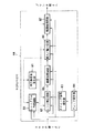
図4は画像処理部44の概略構成を示すブロック図である。ヒストグラム作成回路80はスキャナ部1からの画像データから濃度ヒストグラムを作成する。補正基準値算出部81はヒストグラム作成回路80で作成されたヒストグラムに基づいて補正基準値(後述)を算出する。レンジ補正回路82は補正基準値算出部81からの補正基準値を用いて濃度レンジ(後述)を補正し、リアルタイムに自動濃度調整を行なう。
【0031】
タイミング信号発生部83はクロック発生部84からのクロック信号に基づいて、画像処理部44内の各ブロックに必要な各種タイミング信号を発生する。画質改善回路85はローパスフィルタ及び高域強調回路などが含まれ、レンジ補正回路82によりレンジ補正された画像の画質を更に改善する。拡大/縮小回路86は必要に応じて画像を拡大/縮小し、階調処理回路87はディザ法又は誤差拡散法を用いて画像の階調を処理する。このようにして処理された画像信号はプリンタ部2に送られ画像が形成される。
【0032】
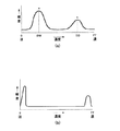
図5は、ヒストグラム作成回路80により作成される濃度ヒストグラムの概略を示す。例えば、A4の1枚の画像を読込む場合、400dpi で読込んだとすると、全画素数Gは次のようになる。
【0033】
G=210×297×(400/25.4)2
この画素数Gの各画素は濃度を有し、ここでは、その濃度を8ビットにて表現する。図5(a)における横軸は、この濃度即ち画素値を示し、縦軸はその濃度に対し、どの濃度の画素が何個存在したかを示す頻度(画素数)である。
【0034】
図5(a)に示すように本実施例では濃度を16に分割し256段階の濃度を16段階に簡略化ている。即ち8ビットの画素値の内、下位4ビットは無視される。16分割を採用することによりハードウエアは大幅に簡略化される。16分割でもヒストグラムとして必要な情報量は、自動濃度調整機能においては十分確保されている。図5(b)は均等16分割の仕方を示し、分割番号0は画素値0〜Fの範囲、分割番号1は画素値10〜1Fの範囲、以下同様に分割番号Fまで画素値範囲が設定される。
【0035】
次に、補正基準値算出部81及びレンジ補正回路82のレンジ補正について説明する。レンジ補正はアナログ複写機における自動露光機能での下地カット等に使用される機能である
一般に、原稿をデジタル的に読取り、濃度ヒストグラムを作成すると図6(a)のようになる。新聞のような原稿の場合、下地濃度がかなりあるので図6(a)のMで示すように下地濃度部分に山が1つでき、Nのように文字濃度部分にも1つの山ができる。ここで、アナログ複写機では、露光ランプを制御して下地濃度部を排除できるが、デジタル複写機では、それができないので下記のような方法で同様の効果を得ている。
【0036】
簡単な例で説明すると、図6(a)に示すMの山とNの山のピークポイントに対応する濃度DW とDB を求め、下記の計算を行なうことにより、濃度ヒストグラムを図6(b)に示すような分布に変換する。ここで、濃度DW とDB は補正基準値と呼ばれ、ヒストグラム作成回路80が作成した各走査ラインでのヒストグラムを基に補正基準値算出部81が算出する。
【0037】
DN =(DI −DW )×FFH /(DB −DW )
ここでDI は入力画素濃度、DN は補正された画素濃度、FFH は最高画素濃度である。すなわち、図6(a)におけるM〜N間のレンジ(濃度幅)は0〜FFhのレンジに広げられる。
【0038】
次に、ヒストグラム作成方式を概説する。下記式は本発明におけるヒストグラム作成の基本計算式であり、ヒストグラムは主走査ライン毎に作成される。1ラインのヒストグラム作成処理が終るごとにレンジ補正の基準値を求め、その基準値を基にレンジ補正処理を行なっている。又、ヒストグラムを構成する総データ数は常に一定の値である。
【0039】
A´=A−αA+αB
ここで、 A´:現ラインの各濃度に対応する補正された頻度(画素数)
A :前ラインまでに計算された各濃度に対応する頻度
B :現ラインの各濃度に対応する頻度
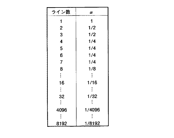
α :重み係数
重み係数αは、各ラインで累積される頻度値に掛ける値で、ヒストグラムに対する寄与率を示している。このαの値は図7に示すように、ライン数に対応して設定され、14値(2のべき乗分の1)すなわち、1,1/2,1/4,1/8,1/16,1/32,……,1/2048,1/4096,1/8192(=1/213)の中から選択される。
【0040】
次にヒストグラム作成回路80について説明する。ヒストグラム作成回路80は、第1に1ライン読取り中に、入力画素毎にA´=(A´)+αBを計算し、第2に1ライン読取りから次のライン読取りの間、即ち画素濃度が入力されていないとき、前記ヒストグラムの各濃度の頻度について(A´)=A−αAを計算する。このようにしてヒストグラム作成回路80は、現ラインに関する補正された頻度値 A´=A−αA+αBを生成する。このようにして作成されたヒストグラムから、補正基準値算出部81によりレンジ補正用の基準値が算出される。
【0041】
又、ヒストグラム作成には2モード、モード0及びモード1が提供され、必要に応じて一方のモードが選択される。
【0042】
モード0:副走査ライン数に依存した重み付け係数変動加算モード
モード1:入力画素に対する重み付け係数一定加算モード
モード0は、前述したように主走査ラインのカウント数に応じて係数αの値を変化させ、ヒストグラムを作成する。モード1は、主走査ラインのカウント値に関係なく、係数を一定としてヒストグラムを作成する。
【0043】
図8はヒストグラム作成回路80の詳細な構成を示すブロック図である。スイッチ62の一方の端子にはスキャナ部1からの画素濃度信号IDAT4〜IDAT7が入力され、カウンタ63からの出力データ信号CDT00〜CDT03が他方の端子に入力される。スイッチ62は又、タイミング信号発生部83からの選択信号に応じてどちらかの入力信号を選択し、選択後の信号SLDT0〜SLDT3をセレクタ66とクロック発生部64へ出力する。ここで画素濃度信号IDAT4〜IDAT7は、画素濃度の上位4ビットであり、IDAT0〜3は前述された理由により無視される。タイミング信号発生部83からのタイミング信号CTL0は各ラインの間、即ち画素濃度信号が読み込まれていないときハイレベルとなり、スイッチ62はカウンタ63からの信号を選択し出力する。
【0044】
カウンタ63は、(A´)=A−αAを計算する時にクロック発生部64及びセレクタ66に必要な値(カウント値)を供給する。カウンタ63は前述の画素濃度信号が読み込まれていないとき、クロック発生部64の16の出力が順番に選択されて発生するための4ビットカウント値を発生する。カウンタ63はタイミング信号発生部83からカウンタクロック信号CT1CKが入力され、タイミング信号発生部83からのカウンタクリア信号CT1CLによりクリアされる。カウンタクリア信号CT1CLは画素濃度信号が読み込まれているときローレベルとなり、カウンタ63をクリアする。
【0045】
クロック発生部64は選択入力信号SLDT0〜3に応じて、16の出力FCK0〜Fの1出力を入力クロック信号MCKの周期で選択し出力する。図9はクロック発生部64の入出力信号の関係を示す。
【0046】
ヒストグラムレジスタ(フリップフロップ)651 〜65F は各画素濃度に対する補正された頻度(WDAT)を、入力クロック信号FCK0〜Fの立ち上がり時にラッチし出力する。入力信号WDATは前述のA’−αA又は(A’)+αBである。ヒストグラムレジスタ651 〜65F からの補正された頻度信号H0〜HFは、補正基準値算出部81へも出力される。
【0047】
セレクタ66は、ヒストグラムレジスタ651 〜65F からの16段階の各濃度H0〜HFに対応した頻度(画素数)が入力され、スイッチ62からの入力信号SLDT0〜SLDT3に応じて、H0〜HFの16データ(各々バス幅26ビット)のうち1データを選択し信号HSDTを出力する。
【0048】
副走査ライン数カウンタ76は図15のタイミングチャートに示すように、タイミング信号発生部83からのライン同期信号HDENが入力され、カウント値信号FDAT00〜FDAT12をクロック発生部75へ出力し、主CPU11からのクリア信号CRSTによって、原稿1ページが走査される毎にクリアされる。
【0049】
クロック発生部75は、副走査ライン数カウンタ76からの出力信号FDAT0〜FDAT12、及びスキャナ部1からの画素同期クロック信号GCKが入力され、信号HCKをカウンタ74及び加算値生成部71へ出力する。クロック発生部75は、信号FDATの値が1,3,7,F,1F,3F,7F,1FF,3FF,7FF,FFF,1FFFのいづれかのときに、入力画素同期クロック信号の1クロックを出力する。クロック発生部75は、アンド回路で構成され、ライン数信号FDATが全て”1”のとき、即ちFDAT=1,3(11),7(111)、F(1111)…のとき、1クロックを出力する。
【0050】
カウンタ74は、クロック発生部75からのクロック信号HCKが入力され、モード0のときカウント値信号CDT20〜CDT23をセレクタ68へ出力する。カウンタ74も主CPU11からのクリア信号CRSTによってページ毎にクリアされる。カウント値CDT20〜CDT23は図7のようにαを選択するための値である。
【0051】
固定係数値レジスタ78はモード1のときの固定係数値を出力する。スイッチ79はCPU11からのモード信号SL1に応じて切り替わり、モード0のときカウンタ74側に設定され、モード1のときレジスタ78側に設定される。
【0052】
減算値生成部67は、(A´)=A−αAを計算する際の”αA”を出力する。減算値生成部67は、セレクタ66からの出力信号HSDTが入力され、信号HSDTを2のべき乗で除算した値を生成する(信号HSDTをシフトする)。
【0053】
セレクタ68は各ラインの間、即ち画素信号が読み込まれていないときに行なわれる演算(A´)=A−αAの”αA”を、入力信号SSL0〜SSL3に応じて決定する。すなわち、セレクタ68は入力信号SSL0〜SSL3の値が”1”の場合は(信号HSDTの値)/2、入力値が”2”の場合は(信号HSDTの値)/22 、……、入力値がCの場合は(信号HSDTの値)/213を出力する。
【0054】
減算部70は、減算(A´)=A−αAを行なう。減算部70は、セレクタ66からの濃度信号HSDT(上式のA)が入力され、セレクタ68からの減算数信号SDT(上式のαA)が入力され、その減算結果として信号YDATが出力される。
【0055】
加算値生成部(シフトレジスタ)71は、A´=(A´)+αBを計算する際の「αB」を生成する。加算値生成部71は、クロック発生部75からのクロックの信号HCKが入力されて信号XDATを加算部69へ出力する。加算値生成部71も又、主CPU11からのクリア信号CRSTによってページ毎にクリアされる。図10は、加算値生成部71の出力例を示すもので、クリア信号CRSTの入力時にイニシャル値出力2000Hで、その後クロック発生部75からのクロック信号HCKが入る毎に現状値の1/2を出力する。この出力は16進数であるので、例えば現状値2000Hの1/2は1000Hとなり、現状値1000Hの1/2は800Hとなる。図11は、信号FDATの変化に対応する各信号の変化を示す。
【0056】
加算部69は、加算A´=(A´)+αBを行なう。加算部69は、セレクタ66からの頻度信号HSDT、及び加算値生成部71からの加算データの信号XDATが入力され、その加算結果として信号ZDATを出力する。図11は、信号ZDATの加算例を示すものである。
【0057】
スイッチ77は、(A´)=A−αAとA´=(A´)+αBの演算の切換えを行なう。スイッチ77の一方の端子には、加算部69からの加算結果信号ZDATが入力され、及び減算部70からの減算結果信号YDATが他方の端子に入力され、選択信号CTL1に応じて一方の入力を選択し、選択結果信号WDATをヒストグラムレジスタ651 〜65F へ出力する。
【0058】
次に、図8に示す構成によるヒストグラムの作成を図13、図14、図15のタイミングチャートを参照して説明する。
【0059】
図13は1ライン読取り中に、入力画素毎にA´=(A´)+αBを計算するときの様子を示すタイミングチャートである。信号MCKはメインクロックで、画素信号に同期している。信号VDENはページ同期信号で、信号HDENはライン同期信号である。スキャナ部1からの画素濃度信号IDAT4〜IDAT7は、画素濃度の上位4ビットであり、スイッチ62へ入力される。副走査有効信号CTL0はこの場合イネーブル(ローレベル)であり、スイッチ62は、入力IDAT4〜IDAT7をセレクタ66及びクロック発生部64へ送る。
【0060】
セレクタ66は画素信号IDAT4〜IDAT7即ち選択入力信号の値に応じて、ヒストグラムレジスタ651 〜65F の出力(頻度)を選択し、選択された頻度信号HSDTを出力する。信号HSDTは加算部69でライン数に応じて重み付けされる係数(XDAT)が加算される。スイッチ77はこの場合入力信号CTL1により加算部69側に設定されているので、加算結果信号ZDATはヒストグラムレジスタ651 〜65F へ戻る。
【0061】
次にクロック発生部64は、画素信号IDAT4〜IDAT7に応じてクロック信号FCK0〜FCKFを出力する。各ヒストグラムレジスタ651 〜65F は各クロック信号FCK0〜FCKFの立ち上がりで、スイッチ77の出力信号WDATの値を各々ラッチ即ち格納する。1ラインの各画素につき、上記処理が行われることにより、1ラインのヒストグラムが生成され、画素濃度調整用の基準値が算出され、その基準値は次ラインでの処理に利用される。
【0062】
次に、1ライン読取りから次のライン読取りの間、即ち画素濃度信号が入力されていないとき、ヒストグラムの各濃度の頻度について(A´)=A−αAを計算する。
【0063】
図14はその減算処理の様子を示すタイミングチャートである。スイッチ62は選択信号CTL0によりカウンタ63側へ切換えられ、スイッチ77は選択信号CTL1により減算器70側へ切換えられる。セレクタ68は、副走査カウンタ数によって決まる係数(モード0時)又は固定係数(モード1時)にて、各々のヒストグラム値を減算する。この減算動作が終った後、通常のヒストグラム作成動作に移る。上述したような動作を繰り返すことにより、モードを0に設定した場合、各主走査ラインを読み込む度に総データ量一定のヒストグラムが作成される。尚、モードを1に設定し、重み付け係数を固定にした場合には、原稿画像の急激な濃度変化にも対応したヒストグラムが得られる。
【0064】
以下に、本発明によるファクシミリ自動モード設定送信の機能について説明する。通常、前記のヒストグラムは各走査ラインの読み取り毎にレンジ補正回路82で使用されているが、本実施例では、原稿の全ての走査ライン読み取り後のヒストグラム処理結果、即ち最終走査ラインで得られたヒストグラムを利用する。尚、このファクシミリ自動モード設定送信機能はプログラムとして、例えばROM41に格納されている。
【0065】
先ず、ファクシミリ送信する相手先のファクス番号等を通常のように設定する。原稿画像データを読み取る前にプリスキャンし、原稿のヒストグラム処理と黒ライ長処理と原稿サイズ検知を行い、これらプリスキャン処理の結果を基にして画像種類の判別を行う。但し、ページ画像を保管可能なメモリがある場合は、プリスキャン動作はせず、スキャン動作は一度だけで画像データをメモリに入れておき、後で処理することもできる。
【0066】
原稿種類の判別処理では、ヒストグラムと黒ラン長の処理結果から、各原稿種類の判別条件に従って原稿の種類が判別される。プリスキャン処理におけるヒストグラム作成動作により求められた各画素濃度に対応する頻度(以下、単にヒストグラム値と記載)は前記のヒストグラムレジスタ651 〜65F からCPUアクセスにより読み出す。
【0067】
又、黒ラン長結果は、黒ラン長の最大値検出処理により求めた値を黒ラン長レジスタ(この黒ラン長レジスタを含め、以下に説明されるレジスタは全て画像処理ASIC内に設けられる)からCPUアクセスにより読み出す。黒ラン長の最大値検出処理は、原稿判別の補正処理として行うもので、原稿の走査ラインの黒画素のつながり(ラン)の最大の長さ(画素数)を求める処理であり、原稿の全ラインのデータの最大値を保持する。
【0068】
但し、前ラインの黒ラン長を参照して処理させて、罫線などの部分はキャンセルするようにしてある。又、黒ラン長の最大値検出処理は、回路規模の制約によりオーバーフロー処理など(8ビット幅)を設け、ビット制限することも考えられる。
【0069】
次に、原稿種類の判別方法を図16〜図18を参照して説明する。先ず、図16のような文字原稿(らしい)の判別を行う。文字原稿らしさの判別は、文字らしさの条件を満たす原稿の場合、文字らしいと判別し、更に中間濃度部の大きさにより、文字原稿と文字/写真原稿を判別をする。文字らしさの判別条件は、下地ピークP1[i]と前後の分割番号P1[i−1],P1[i+1]と、文字ピークP2[i]と前後の分割番号P2[i−1,P2[i+1]の頻度の総和が全体に対してどのくらいの割合かを求める。
【0070】
文字らしさの条件レジスタとして、文字頻度判定閾値を設け、上記の総和が文字頻度判定閾値(Cth)以上の場合、文字らしいと判定する。
【0071】
WA1=P1[i−1]+P1[i]+P1[i+1]
WA2=P2[i−1]+P2[i]+P2[i+1]
WA=WA1+WA2
WA≧Cthの場合、文字らしい原稿と判別する。これ以外の場合、文字らしくない原稿と判別する。
【0072】
文字らしい原稿の場合は、次に、中間濃度範囲の処理レジスタとして、中間濃度判定閾値レジスタを設け、中間濃度範囲Aの判別条件により、文字原稿と文字/写真原稿を判別する。中間濃度範囲Aの判別条件は、下地ピーク濃度より3分割大きい番号P1[i+3]から文字ピーク濃度より3分割小さい番号P2[i−3]の間で、中間濃度判定閾値Pth(頻度)を基に判別する。
【0073】
中間濃度範囲A内の全てのヒストグラム値がPthより小さい場合、文字原稿と判別する。これ以外の場合、文字/写真原稿と判別する。
【0074】
更に、文字と判定した原稿は、画像細密度の判定、即ち細字文字原稿の判定を行う。細字文字原稿の判定は、ファクシミリ送信の解像度設定をするために必要である。この解像度の設定には標準と高精細があり、細字文字原稿と判定された場合、解像度は高精細に設定される。
【0075】
細字文字原稿の条件判定は、条件レジスタとして黒幅判定係数及び黒ラン長閾値レジスタを設け、文字ピーク濃度の前後3分割の幅Cでの各ヒストグラム値が全て細字判定閾値Xより大きい場合で、かつ、最大黒ラン長が黒ラン長閾値(BKmax)より小さい場合、細字文字原稿と判別する。
【0076】
X=文字ピーク値P2×黒幅判定係数/16
細字判別範囲C内の全てのヒストグラム値がXより大きく、かつ、黒ラン長<BKmaxの場合、細字文字原稿と判定する。これ以外の場合、標準文字原稿と判定する。尚、この黒幅判定係数は例えば4である。
【0077】
次に、図17のような写真原稿の判別を行う。前記で文字らしくない判定をした原稿は、写真原稿の判別条件により、写真原稿と文字/写真原稿を判別する。
【0078】
写真原稿の判別条件は、条件レジスタとして白幅判定係数レジスタを設け、ピークP3の前後3分割の幅Bのヒストグラム値が写真原稿判定閾値Zより大きい場合、写真原稿と判別する。
【0079】
Z=ピーク値P3×白幅判定係数/16
写真原稿判別範囲B内の全てのヒストグラム値がZより大きい場合、写真原稿と判別する。これ以外の場合、文字/写真原稿と判別する。尚、この白幅判定係数は例えば8である。上記の原稿判別結果以外の種類に判定される文字/写真原稿の例を図18に示す。
【0080】
又、上記の各原稿種類に対応するASIC(application specific IC) は、画質モード設定用レジスタが設けられる。このASIC画質モード設定用レジスタは、各原稿種類(標準文字、細字文字、写真、文字/写真)により、原稿画像を画像処理するモード、つまり、ASICへ設定するパラメータを切り換える画質モードを設定するためのレジスタである。
【0081】
ASIC画質モード設定は、画像処理部のレンジ補正処理、ノイズ除去とMTF補正を行うフィルタ補正処理、拡大/縮小処理、文字/写真/網点領域を識別する像域識別処理、及び、編集処理、階調処理の処理方法などのパラメータ設定をCPUアクセスにより行っている。
【0082】
例えば、画質モードが文字、写真、文字/写真の3種類をもつ場合、次のように設定する。(a)標準文字原稿の場合、画質モードを文字モードと設定する。(b)細字文字原稿の場合、画質モードを文字モードと設定する。(c)写真原稿の場合、画質モードを写真モードと設定する。(d)文字/写真原稿の場合、画質モードを文字/写真モードと設定する。
【0083】
又、各原稿種類に対応するファクシミリ解像度設定用レジスタが設けられる。このレジスタは、各原稿種類(標準文字、細字文字、写真、文字/写真)により、ファクシミリ送信する場合の解像度を設定する。
例えば、ファクシミリ機能として解像度が標準と高精細モードをもつ場合、次のようにする。(a)標準文字原稿の場合、解像度を標準モード設定とする。(b)細字文字原稿の場合、高精細モード設定とする。(c)写真原稿の場合、標準モード設定とする。(d)文字/写真原稿の場合、標準モード設定とする。
【0084】
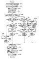
次に具体的なファクシミリ自動モード設定送信機能の手順の例を図1のフローチャートを参照して説明する。コンパネ17上にはファクシミリ自動モード設定送信機能の切換スイッチ等(図示せず)が設けられ、デジタル複写機の起動時に自動的にモード設定を行うモードと、手動により各モード設定を行うモードとを切り換えることができる。
【0085】
デジタル複写機の電源投入時、不揮発性メモリROM41に記憶しておいた初期値を、ASIC内の条件設定レジスタとモード設定レジスタに設定する。ファクシミリ自動モード設定送信機能が選択されている場合(ST1)、以下の手順により処理を行う。
【0086】
先ず、ファクシミリ送信する相手先のファクス番号等の設定が行なわれる(ST2)。次に、原稿台上に原稿をプリスキャン処理(ST3)により、原稿サイズ即ち送信サイズ検知処理と、原稿範囲のヒストグラム処理と、黒ラン長の最大値検出処理を行う(ST4)。そして、原稿の送信サイズと、画像濃度を16分割したヒストグラムと、黒ラン長を画像処理ASICの専用レジスタからCPUアクセスによりデータを読み出す(ST5)。
【0087】
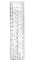
次に、読み出したヒストグラムから原稿判別処理を行う。ここではヒストグラム処理の結果を表1のように仮定する。
【0088】
【表1】
先ず、文字原稿らしさの判別処理を実行する(ST6)。文字頻度判定閾値(Cth)は3500画素とする。
【0090】
WA1=P1[i−1]+P1[i]+P1[i+1]=2133
WA2=P2[i−1]+P2[i]+P2[i+1]=1490
WA=WA1+WA2=3623
WA≧Cthの条件を満足しているので、文字原稿らしいと判別する。
【0091】
次に、中間濃度範囲の判別を実行する(ST12)。ここで中間濃度判定閾値(Pth)は220(画素)とする。中間濃度範囲A部は、前述の範囲のように分割番号4からAで、全て中間濃度判定閾値(Pth)より小さい値のため、文字原稿と判別する。
【0092】
次に、細字文字原稿の判定を実行する(ST13)。黒幅判定係数を4とし、黒ラン長閾値BKmaxを160(画素)とする。細字判定範囲Cは、前記の範囲(文字ピークの前後3分割の幅)であるから分割番号AからFである。処理して読み出した黒ラン長(最大黒ラン長)は200画素とすると、細字判定閾値Xは次のようになる。
【0093】
X=文字ピーク値P2×黒幅判定係数/16=928×4/16=232
細字判定範囲C内の全てのヒストグラム値がXより大きく、かつ、黒ラン長<BKmaxの条件を満足しないため、標準文字原稿と判定する。 次に、原稿種類が標準文字原稿と判別されたので、事前に設定しておいた(前記の設定内容)ように、画像処理の画質モードを文字モードと設定し、ファクシミリ送信の解像度を標準モード設定(C)とする(ST15)。
【0094】
以上の処理により求められた原稿種類、及び原稿種類に対応した各モード設定内容をコンパネ表示させてユーザに確認させる。そのままのモード設定内容では問題がある場合は、コンパネ操作によりモード設定内容の変更を行った上でファクシミリ送信動作に移る。
【0095】
次に、送信サイズと解像度をファクシミリ処理部56へ送り、原稿読み取り動作(ST20)により原稿を読み取り、設定された画質モードで画像データを処理し(ST21)、処理された画像データを更にファクシミリ処理部へ送る(ST22)。
【0096】
この後、ファクシミリ処理部は、通常のファクシミリ送信手順により、相手先の機能に合わせて、送信する解像度と送信サイズを再変換する必要がある場合は変換などをしたあと送信する(ST23)。これらのファクシミリ自動モード設定送信の操作は原稿単位に繰り返えされる。
【0097】
尚、自動モード設定機能はファクシミリ送信に適用した場合が説明されたが、勿論、本画像形成装置が原稿画像を複写する場合にも適用できる。このような場合、原稿画像の種類は自動的に判断され、最適なモードで画像がプリンタ部2で印刷される。
【0098】
【発明の効果】
本発明により、ファクシミリ機能をもったデジタル複写機で、種類の混在した原稿を送信する場合でも、ユーザーは送信相手先の設定をするだけでファクシミリ送信に必要な各モードを設定する必要はない。原稿毎に、原稿の画質モードと、ファクシミリ送信する解像度と、送信サイズの設定を自動的に行うことが可能となる。又、デジタル複写機のファクシミリ機能設定操作の簡略化が可能となり、ファクシミリ送信時の各種モード設定における設定ミスや設定忘れを防止することができる。
【図面の簡単な説明】
【図1】本発明によるファクシミリ自動モード設定送信機能の手順を示すフローチャート。
【図2】この発明に係る画像形成装置の概略構成を示す断面図。
【図3】この発明に係る画像形成装置の制御系の概略構成を示す図。
【図4】この発明に係る画像形成装置における画像処理部の概略構成を示す図。
【図5】この発明において作成されるヒストグラムを説明するための図。
【図6】補正基準値及びレンジ補正を説明するためのヒストグラム図。
【図7】モード0における副走査ライン数と、それに対応する係数αを説明するための図。
【図8】この発明の一実施例に係る画像形成装置におけるヒストグラム作成回路の構成を示すブロック図。
【図9】クロック発生部における入力画素濃度に対応する出力クロック信号のタイミングを説明するための図。
【図10】加算値生成部の出力例を示す図。
【図11】信号FDATの変化に対応する各信号の変化を示す図。
【図12】信号ZDATの加算例を示す図。
【図13】ヒストグラム作成回路の動作を説明するためのタイミングチャート。
【図14】ヒストグラム作成回路の動作を説明するためのタイミングチャート。
【図15】ヒストグラム作成回路の動作を説明するためのタイミングチャート。
【図16】文字原稿らしさの判別を説明するためのヒストグラム。
【図17】写真原稿らしさの判別を説明するためのヒストグラム。
【図18】文字/写真原稿らしさの判別を説明するためのヒストグラム。
【符号の説明】
1…スキャナ部 2…プリンタ部
3…蛍光灯光源 6…感光体ドラム
7…現像装置 91…原稿スケール
92…原稿ガラス 102…帯電装置
104…クリーナユニット 105…転写装置
106…剥離装置 107…消去装置
108…走査ユニット 116…レンズユニット[0001]
BACKGROUND OF THE INVENTION
The present invention relates to an image forming apparatus such as a copying machine, and more particularly to an image forming apparatus having a facsimile function.
[0002]
[Prior art]
Each company has already announced a product with a facsimile function as a multifunction machine of a digital copying machine. Among these facsimile functions, when image data is transmitted, the user manually sets the transmission destination, the image processing image quality mode, the transmission resolution, and the transmission size as the settings of the facsimile function section. .
[0003]
If the set contents are not compatible with the destination device, the facsimile transmission processing unit re-converts the resolution and transmission size before transmitting. As a method for creating a histogram, an apparatus having a range correction function has been developed as an automatic density adjustment.
[0004]
[Problems to be solved by the invention]
When sending image data with a digital copying machine with a conventional facsimile function, the user manually sets the image processing mode, the resolution and the transmission size of the destination image processing as the settings of the facsimile function section. It was necessary to set it in, and troublesome operation was necessary. In particular, when various originals such as a character original, a photo original, and a small character (small character) original are to be transmitted simultaneously, it is necessary to set these transmission modes for each original.
[0005]
Also, since various mode settings at the time of facsimile transmission are manual settings, there is a risk of setting mistakes or forgetting to set.
[0006]
SUMMARY OF THE INVENTION Accordingly, an object of the present invention is to provide a digital image forming apparatus having a function of automatically switching an image quality mode and resolution depending on a document type and transmitting a fax.
[0007]
[Means for Solving the Problems]
In order to achieve the above object, an image forming apparatus according to the present invention includes a scanning unit that scans a document and provides image data corresponding to the document image, a histogram creation unit that creates a histogram of pixel density from the image data, The histogram provided from the histogram creation means is analyzed based on the document discrimination condition, the discrimination means for discriminating the type of the original, the detection means for detecting the size of the original, and the detection means provided from the detection means. A communication unit that transmits input image data to an external communication line according to the document size, and the image data provided from the scanning unit is processed according to an image quality mode, and the processed image is transmitted to the communication unit. The image processing unit automatically transfers the image quality mode of the image processing unit according to the image processing unit to be transferred and the type of the document determined by the determining unit. A setting unit configured to set, and means for forming an image based on image data received in the communication unit via the external communication line.
[0008]
The image forming apparatus according to the present invention includes a scanning unit that scans a document and provides image data corresponding to the document image, a histogram generating unit that generates a histogram in which the image data is divided into a predetermined number of steps, and the histogram Analyzing the histogram provided by the creating means, determining a document type as one of a character, a photograph, and a character / photo; a detecting means for detecting the size of the document;
Based on the document size detected by the detection means, a communication means for transmitting input image data to an external communication line, and the image data provided from the scanning means is processed according to an image quality mode, and processed. An image processing means for transferring the image to the communication means, a setting means for setting the image quality mode of the image processing means in accordance with the type of document determined by the determination means, and the external communication line. Means for forming an image based on the image data received by the communication means, and at the time of facsimile transmission, the type of the original is determined for each original, the setting of the image quality mode of the image processing means is switched, and the processing The image data processed by the means is transmitted to the external communication line.
[0009]
The discrimination means adds a frequency value near the original background density and a frequency value near the character density, and the added value is equal to or greater than a first predetermined value, and each frequency value of the intermediate density is a second predetermined value. If it is smaller, the document is determined to be a character document, and if there is an intermediate density value greater than the second predetermined value, the document is determined to be a character / photo document.
[0010]
An image forming apparatus according to the present invention includes a scanning unit that scans a document and provides image data corresponding to the document image, a histogram generating unit that generates a histogram obtained by dividing the image data into a predetermined number of steps, The histogram provided from the histogram creation means is analyzed to determine the document type, and (a) the frequency value near the document background density and the frequency value near the character density are added, and this added value is a first predetermined value. When the frequency values of the intermediate density are all smaller than the second predetermined value, the document is determined to be a character document, and when the frequency values of the intermediate density are larger than the second predetermined value, (B) calculating a black run length indicating a connection of black pixels in the main scanning direction of the document image data when the document is determined to be a character document; Second discriminating means for discriminating the fine density of the document based on the maximum value of the black run length; and (c) adding the frequency value near the document background density and the frequency value near the character density, and adding the value Is less than the first predetermined value, and when the frequency values in the predetermined density area of the histogram are all larger than the third predetermined value, the original is determined as a photo original, and each frequency value in the predetermined density area of the histogram is determined. When there is a frequency value smaller than the third predetermined value, the image data provided from the scanning unit and the image data provided from the scanning unit are set in the image quality mode. An image processing unit that processes the image processing unit, a setting unit that sets the image quality mode of the image processing unit according to the type of document determined by the determination unit, and an image data processed by the image processing unit. And means for forming an image.
[0011]
The image forming method according to the present invention scans a document, provides image data corresponding to the document image, determines the type of the document based on the image data, and determines the type of document determined by the determination unit. Processing the image data accordingly, providing the processed image data, facsimile transmitting the processed image data to an external communication line, and based on the image data received via the external communication line Forming an image.
[0012]
Accordingly, as the pre-scan process, the transmission size, the histogram, and the maximum black run length are obtained, and the type of document is determined based on the obtained values. Even when sending various types of documents using the facsimile function, the user only needs to set the transmission destination without setting each mode required for facsimile transmission. The resolution and the transmission size are automatically set for each document.
[0013]
DETAILED DESCRIPTION OF THE INVENTION
Hereinafter, an embodiment of the present invention will be described with reference to the drawings. FIG. 2 shows a schematic configuration of an image forming apparatus to which the present invention is applied. The image forming apparatus includes a
[0014]
The
[0015]
On the side of the
[0016]
The document placed on the document table 117 is exposed and scanned when the scanning system including the
[0017]
The reflected light from the original by the scanning of the scanning system, that is, the reflected light from the original by the light irradiation of the
[0018]
The
[0019]
The
[0020]
Around the
[0021]
A
[0022]
A sheet is fed between the developing
[0023]
In the direction in which the sheet onto which the toner image has been transferred is peeled off from the
[0024]
The paper on which the toner image has been fixed by the fixing
[0025]
FIG. 3 is a block diagram showing a schematic configuration of a control system of the image forming apparatus. This apparatus is controlled by a main CPU 11, a control panel CPU 12, a
[0026]
A control panel (control panel) CPU 12 is connected to the
[0027]
The printer CPU 14 is controlled by communication with the main CPU 11, and based on data in the ROM 31 and
[0028]
The main CPU 11 comprehensively controls the image forming apparatus in accordance with control programs stored in the
[0029]
The
[0030]
FIG. 4 is a block diagram showing a schematic configuration of the
[0031]
The timing
[0032]
FIG. 5 shows an outline of the density histogram created by the
[0033]
G = 210 × 297 × (400 / 25.4)2
Each pixel of this pixel number G has a density, and here, the density is expressed by 8 bits. The horizontal axis in FIG. 5A indicates this density, that is, the pixel value, and the vertical axis indicates the frequency (number of pixels) indicating how many pixels of which density exist with respect to the density.
[0034]
As shown in FIG. 5A, in this embodiment, the density is divided into 16 and the density in 256 levels is simplified to 16 levels. That is, the lower 4 bits of the 8-bit pixel value are ignored. By adopting 16 divisions, the hardware is greatly simplified. Even with 16 divisions, the amount of information required as a histogram is sufficiently secured in the automatic density adjustment function. FIG. 5 (b) shows a method of dividing into 16 equal parts,
[0035]
Next, the range correction of the correction reference
In general, when a document is read digitally and a density histogram is created, the result is as shown in FIG. In the case of a manuscript such as a newspaper, the background density is considerable, so that one peak is formed in the background density portion as indicated by M in FIG. 6A, and one peak is also formed in the character density portion such as N. Here, in the analog copying machine, the background density portion can be eliminated by controlling the exposure lamp. However, since the digital copying machine cannot do this, the same effect is obtained by the following method.
[0036]
To explain with a simple example, density DW and DB corresponding to peak points of M peak and N peak shown in FIG. 6 (a) are obtained, and the density histogram is shown in FIG. 6 (b) by performing the following calculation. Convert to the distribution shown in. Here, the densities DW and DB are called correction reference values, and are calculated by the correction reference
[0037]
DN = (DI-DW) * FFH / (DB-DW)
Here, DI is the input pixel density, DN is the corrected pixel density, and FFH is the maximum pixel density. That is, the range (density range) between M and N in FIG. 6A is expanded to a range of 0 to FFh.
[0038]
Next, the histogram creation method will be outlined. The following formula is a basic calculation formula for creating a histogram in the present invention, and the histogram is created for each main scanning line. Every time one line of histogram creation processing is completed, a range correction reference value is obtained, and the range correction processing is performed based on the reference value. Further, the total number of data constituting the histogram is always a constant value.
[0039]
A ′ = A−αA + αB
A ′: corrected frequency (number of pixels) corresponding to each density of the current line
A: Frequency corresponding to each concentration calculated up to the previous line
B: Frequency corresponding to each concentration of the current line
α: Weight coefficient
The weighting factor α is a value multiplied by the frequency value accumulated in each line, and indicates a contribution rate to the histogram. As shown in FIG. 7, the value of α is set corresponding to the number of lines, and 14 values (one power of 2), that is, 1, 1/2, 1/4, 1/8, 1/16 , 1/32,..., 1/2048, 1/4096, 1/8192 (= 1/213) Is selected.
[0040]
Next, the
[0041]
Also, two modes,
[0042]
Mode 0: Weighting coefficient fluctuation addition mode depending on the number of sub-scanning lines
Mode 1: Weighting factor constant addition mode for input pixels
In
[0043]
FIG. 8 is a block diagram showing a detailed configuration of the
[0044]
The
[0045]
The
[0046]
Histogram register (flip-flop) 651~ 65FLatches and outputs the corrected frequency (WDAT) for each pixel density when the input clock signals FCK0 to FCK rise. The input signal WDAT is A′−αA or (A ′) + αB described above. Histogram register 651~ 65FThe corrected frequency signals H <b> 0 to HF are also output to the correction reference
[0047]
The
[0048]
As shown in the timing chart of FIG. 15, the sub-scan
[0049]
The
[0050]
The
[0051]
The fixed coefficient value register 78 outputs a fixed coefficient value in
[0052]
The subtraction
[0053]
The
[0054]
The subtracting
[0055]
The addition value generation unit (shift register) 71 generates “αB” for calculating A ′ = (A ′) + αB. The addition
[0056]
The adding
[0057]
The
[0058]
Next, the creation of a histogram with the configuration shown in FIG. 8 will be described with reference to the timing charts of FIGS.
[0059]
FIG. 13 is a timing chart showing how A ′ = (A ′) + αB is calculated for each input pixel during one line reading. The signal MCK is a main clock and is synchronized with the pixel signal. The signal VDEN is a page synchronization signal, and the signal HDEN is a line synchronization signal. Pixel density signals IDAT4 to IDAT7 from the
[0060]
The
[0061]
Next, the
[0062]
Next, during one line reading to the next line reading, that is, when no pixel density signal is input, (A ′) = A−αA is calculated for the frequency of each density in the histogram.
[0063]
FIG. 14 is a timing chart showing the state of the subtraction process. The
[0064]
The function of facsimile automatic mode setting transmission according to the present invention will be described below. Normally, the histogram is used by the
[0065]
First, the fax number or the like of the destination for facsimile transmission is set as usual. Pre-scanning is performed before document image data is read, histogram processing of the document, black line length processing, and document size detection are performed, and the image type is determined based on the results of these pre-scan processing. However, if there is a memory that can store page images, the pre-scan operation is not performed, and the scan operation can be performed only once, and the image data can be stored in the memory and processed later.
[0066]
In the document type determination process, the document type is determined from the processing result of the histogram and the black run length according to the determination condition of each document type. The frequency corresponding to each pixel density obtained by the histogram creation operation in the pre-scan process (hereinafter simply referred to as a histogram value) is the histogram register 65 described above.1~ 65FIs read by CPU access.
[0067]
Also, the black run length result is obtained by using the black run length maximum value detection process to obtain the black run length register (all registers described below including this black run length register are provided in the image processing ASIC). Is read by CPU access. The black run length maximum value detection process is performed as a document discrimination correction process, and is a process for obtaining the maximum length (number of pixels) of black pixel connections (runs) on the scan line of the document. Holds the maximum value of the line data.
[0068]
However, the processing is performed with reference to the black run length of the previous line, and the ruled lines and the like are cancelled. Also, the black run length maximum value detection processing may be limited by providing overflow processing or the like (8-bit width) due to circuit scale restrictions.
[0069]
Next, a method for determining the document type will be described with reference to FIGS. First, a character original (likely) as shown in FIG. 16 is determined. Character originality is determined to be a character in the case of an original that satisfies the characteristic conditions, and further, a character original and a character / photo original are determined based on the size of the intermediate density portion. Characteristic determination conditions are: base peak P1 [i] and preceding and following division numbers P1 [i-1] and P1 [i + 1], character peak P2 [i] and preceding and following division numbers P2 [i-1, P2 [ What is the ratio of the sum of the frequencies of i + 1] to the whole.
[0070]
A character frequency determination threshold is provided as a character-like condition register. When the above sum is equal to or greater than the character frequency determination threshold (Cth), it is determined that the character is likely to be a character.
[0071]
WA1 = P1 [i-1] + P1 [i] + P1 [i + 1]
WA2 = P2 [i-1] + P2 [i] + P2 [i + 1]
WA = WA1 + WA2
When WA ≧ Cth, the document is determined to be a character-like document. In other cases, the document is determined not to be text.
[0072]
In the case of a document that seems to be a character, an intermediate density determination threshold value register is provided as a processing register for the intermediate density range, and a character original and a character / photo original are discriminated based on the determination condition of the intermediate density range A. The determination condition of the intermediate density range A is based on the intermediate density determination threshold Pth (frequency) between the number P1 [i + 3] that is three divisions larger than the background peak density and the number P2 [i-3] that is three divisions smaller than the character peak density. To determine.
[0073]
When all the histogram values in the intermediate density range A are smaller than Pth, it is determined as a character document. In other cases, it is determined as a text / photo original.
[0074]
Furthermore, the document determined to be a character is subjected to image fine density determination, that is, determination of a thin character document. The determination of a fine character original is necessary for setting the resolution for facsimile transmission. There are two types of resolution settings: standard and high definition. If it is determined that the document is a fine character document, the resolution is set to high definition.
[0075]
The condition determination of the fine character original is performed when the black width determination coefficient and the black run length threshold value register are provided as the condition registers, and all the histogram values in the width C of the three divisions before and after the character peak density are all larger than the fine character determination threshold X. If the maximum black run length is smaller than the black run length threshold (BKmax), it is determined as a fine character original.
[0076]
X = character peak value P2 × black width determination coefficient / 16
When all the histogram values in the fine character discrimination range C are larger than X and the black run length <BKmax, it is judged as a fine character original. In other cases, it is determined as a standard character document. The black width determination coefficient is 4, for example.
[0077]
Next, the photographic document as shown in FIG. 17 is determined. The original that has been determined not to be textual as described above is discriminated between a photographic original and a character / photo original according to the photographic original determination conditions.
[0078]
As a condition for determining a photo original, a white width determination coefficient register is provided as a condition register, and when the histogram value of the width B of the three divisions before and after the peak P3 is larger than the photo original determination threshold Z, it is determined as a photo original.
[0079]
Z = peak value P3 × white width determination coefficient / 16
When all the histogram values in the photo original determination range B are larger than Z, it is determined as a photo original. In other cases, it is determined as a text / photo original. The white width determination coefficient is 8, for example. FIG. 18 shows an example of a character / photo original determined to be of a type other than the original determination result.
[0080]
An ASIC (application specific IC) corresponding to each document type is provided with an image quality mode setting register. This ASIC image quality mode setting register is used to set a mode for image processing of a document image, that is, an image quality mode for switching a parameter set to the ASIC, according to each document type (standard character, fine character, photo, character / photo). Register.
[0081]
The ASIC image quality mode setting includes a range correction process of the image processing unit, a filter correction process for performing noise removal and MTF correction, an enlargement / reduction process, an image area identification process for identifying a character / photo / halftone area, and an editing process. Parameter settings such as the gradation processing method are performed by CPU access.
[0082]
For example, when the image quality mode has three types of characters, photos, and characters / photos, the following settings are made. (A) In the case of a standard character document, the image quality mode is set to the character mode. (B) For a fine character original, the image quality mode is set to the character mode. (C) In the case of a photo original, the image quality mode is set to the photo mode. (D) In the case of a text / photo original, the image quality mode is set to text / photo mode.
[0083]
A facsimile resolution setting register corresponding to each document type is provided. This register sets the resolution for facsimile transmission according to each document type (standard character, fine character, photo, character / photo).
For example, when the facsimile function has a standard resolution and a high-definition mode, the following is performed. (A) In the case of a standard character document, the resolution is set to the standard mode. (B) In the case of a fine character original, the high-definition mode is set. (C) In the case of a photo original, the standard mode is set. (D) For text / photo originals, the standard mode is set.
[0084]
Next, an example of a procedure of a specific facsimile automatic mode setting transmission function will be described with reference to the flowchart of FIG. The
[0085]
When the digital copying machine is turned on, initial values stored in the
[0086]
First, the fax number and the like of the destination for facsimile transmission are set (ST2). Next, a document size or transmission size detection process, a document range histogram process, and a black run length maximum value detection process are performed by a prescan process (ST3) on the document table (ST4). Then, data is read by CPU access from the dedicated register of the image processing ASIC for the transmission size of the document, the histogram obtained by dividing the image density into 16 and the black run length (ST5).
[0087]
Next, document discrimination processing is performed from the read histogram. Here, the result of the histogram processing is assumed as shown in Table 1.
[0088]
[Table 1]
First, a character originalness determination process is executed (ST6). The character frequency determination threshold (Cth) is 3500 pixels.
[0090]
WA1 = P1 [i−1] + P1 [i] + P1 [i + 1] = 2133
WA2 = P2 [i−1] + P2 [i] + P2 [i + 1] = 1490
WA = WA1 + WA2 = 3623
Since the condition of WA ≧ Cth is satisfied, it is determined that the original is a character document.
[0091]
Next, the intermediate density range is determined (ST12). Here, the intermediate density determination threshold (Pth) is 220 (pixels). The intermediate density range A part is determined to be a character document because it is divided by the
[0092]
Next, a fine character original determination is executed (ST13). The black width determination coefficient is set to 4, and the black run length threshold BKmax is set to 160 (pixels). Since the thin character determination range C is the above-mentioned range (width of three divisions before and after the character peak), it is division numbers A to F. If the black run length (maximum black run length) read out after processing is 200 pixels, the fine character determination threshold value X is as follows.
[0093]
X = character peak value P2 × black width determination coefficient / 16 = 928 × 4/16 = 232
Since all the histogram values in the fine character determination range C are larger than X and the condition of black run length <BKmax is not satisfied, it is determined as a standard character document. Next, since the document type is determined to be a standard character document, the image processing image quality mode is set to the character mode and the facsimile transmission resolution is set to the standard mode as previously set (described above). Set (C) (ST15).
[0094]
The original type obtained by the above processing and the mode setting contents corresponding to the original type are displayed on the control panel to allow the user to confirm. If there is a problem with the mode setting contents as they are, the mode setting contents are changed by a panel operation, and then the facsimile transmission operation is started.
[0095]
Next, the transmission size and resolution are sent to the
[0096]
Thereafter, the facsimile processing unit performs transmission after performing conversion or the like if it is necessary to reconvert the transmission resolution and transmission size in accordance with the function of the other party according to the normal facsimile transmission procedure (ST23). These facsimile automatic mode setting transmission operations are repeated for each original.
[0097]
Although the automatic mode setting function has been described as applied to facsimile transmission, it is of course applicable to the case where the image forming apparatus copies a document image. In such a case, the type of document image is automatically determined, and the image is printed by the
[0098]
【The invention's effect】
According to the present invention, even when a digital copier having a facsimile function transmits a mixed-type document, the user does not need to set each mode necessary for facsimile transmission only by setting a transmission destination. For each original, it is possible to automatically set the original image quality mode, the resolution for facsimile transmission, and the transmission size. Further, the facsimile function setting operation of the digital copying machine can be simplified, and setting mistakes or forgetting to set in various modes at the time of facsimile transmission can be prevented.
[Brief description of the drawings]
FIG. 1 is a flowchart showing a procedure of a facsimile automatic mode setting transmission function according to the present invention.
FIG. 2 is a cross-sectional view showing a schematic configuration of an image forming apparatus according to the present invention.
FIG. 3 is a diagram showing a schematic configuration of a control system of the image forming apparatus according to the present invention.
FIG. 4 is a diagram showing a schematic configuration of an image processing unit in the image forming apparatus according to the present invention.
FIG. 5 is a diagram for explaining a histogram created in the present invention.
FIG. 6 is a histogram for explaining a correction reference value and range correction.
7 is a diagram for explaining the number of sub-scanning lines in
FIG. 8 is a block diagram showing a configuration of a histogram creation circuit in the image forming apparatus according to one embodiment of the present invention.
FIG. 9 is a diagram for explaining timing of an output clock signal corresponding to an input pixel density in a clock generation unit.
FIG. 10 is a diagram illustrating an output example of an addition value generation unit.
FIG. 11 is a diagram illustrating changes in signals corresponding to changes in the signal FDAT.
FIG. 12 is a diagram illustrating an addition example of a signal ZDAT.
FIG. 13 is a timing chart for explaining the operation of the histogram creation circuit;
FIG. 14 is a timing chart for explaining the operation of the histogram creation circuit;
FIG. 15 is a timing chart for explaining the operation of the histogram creation circuit;
FIG. 16 is a histogram for explaining determination of character originalness.
FIG. 17 is a histogram for explaining determination of a photo originalness.
FIG. 18 is a histogram for explaining determination of character / photograph originality.
[Explanation of symbols]
1 ...
3 ... Fluorescent
7 ...
92 ...
104 ...
106 ...
108: Scanning unit 116: Lens unit
Claims (8)
前記画像データから画素濃度のヒストグラムを作成するヒストグラム作成手段と、
前記ヒストグラム作成手段から提供される前記ヒストグラムを原稿判別条件に基づいて解析し、前記原稿の種類を判別する判別手段と、
前記原稿のサイズを検知する検知手段と、
前記検出手段から提供される前記原稿サイズに応じて、入力画像データを外部通信回線に対して送信する通信手段と、
前記走査手段から提供される前記画像データを画質モードに応じて処理し、処理された画像を前記通信手段に転送する画像処理手段と、
前記判別手段により判別された原稿の種類に応じて、前記画像処理手段の前記画質モードを自動的に設定する設定手段と、
前記外部通信回線を介して前記通信手段に受信された画像データに基づいて画像を形成する手段と、
を具備することを特徴とする画像形成装置。Scanning means for scanning a document and providing image data corresponding to the document image;
Histogram creation means for creating a pixel density histogram from the image data;
Analyzing the histogram provided from the histogram creating means based on a document determining condition, and determining a type of the document;
Detecting means for detecting the size of the document;
Communication means for transmitting input image data to an external communication line in accordance with the document size provided from the detection means;
Image processing means for processing the image data provided from the scanning means according to an image quality mode, and transferring the processed image to the communication means;
A setting unit that automatically sets the image quality mode of the image processing unit according to the type of document determined by the determination unit;
Means for forming an image based on image data received by the communication means via the external communication line;
An image forming apparatus comprising:
前記画像データを所定数の段階に濃度分割したヒストグラムを作成するヒストグラム作成手段と、
前記ヒストグラム作成手段から提供される前記ヒストグラムを解析し、原稿種類を文字、写真、文字/写真の中の1つとして判別する判別手段と、
前記原稿のサイズを検知する検知手段と、
前記検知手段により検知された原稿サイズに基づいて、入力画像データを外部通信回線に対して送信する通信手段と、
前記走査手段から提供される前記画像データを画質モードに応じて処理し、処理された画像を前記通信手段に転送する画像処理手段と、
前記判別手段により判別された原稿の種類に応じて、前記画像処理手段の前記画質モードを設定する設定手段と、
前記外部通信回線を介して前記通信手段に受信された画像データに基づいて画像を形成する手段と、
を具備し、ファクシミリ送信時に、原稿毎に原稿の種類を判別し、前記画像処理手段の画質モードの設定を切り換え、前記処理手段により処理された画像データを前記外部通信回線に送信することを特徴とする画像形成装置。Scanning means for scanning a document and providing image data corresponding to the document image;
Histogram creation means for creating a histogram obtained by dividing the image data into a predetermined number of steps;
A discriminating unit that analyzes the histogram provided from the histogram creating unit and discriminates a document type as one of a character, a photograph, and a character / photo;
Detecting means for detecting the size of the document;
Communication means for transmitting input image data to an external communication line based on the document size detected by the detection means;
Image processing means for processing the image data provided from the scanning means according to an image quality mode, and transferring the processed image to the communication means;
A setting unit for setting the image quality mode of the image processing unit according to the type of the document determined by the determination unit;
Means for forming an image based on image data received by the communication means via the external communication line;
And at the time of facsimile transmission, the type of the original is determined for each original, the setting of the image quality mode of the image processing means is switched, and the image data processed by the processing means is transmitted to the external communication line. An image forming apparatus.
前記画像データを所定数の段階に濃度分割したヒストグラムを作成するヒストグラム作成手段と、
前記ヒストグラム作成手段から提供される前記ヒストグラムを解析し、原稿種類を判別し、
(a)前記原稿下地濃度付近の頻度値と、文字濃度付近の頻度値を加算し、この加算値が第1所定値以上であって、中間濃度の各頻度値が全て第2所定値より小さい場合、前記原稿を文字原稿と判断し、中間濃度の各頻度値に前記第2所定値より大きなものがある場合、前記原稿を文字/写真混在原稿と判別する第1判別手段と、
(b)前記原稿が文字原稿と判断されたとき、前記原稿画像データの主走査方向の黒画素のつながりを示す黒ラン長を計算し、前記黒ラン長の最大値に基づき前記原稿の細密度を判別する第2判別手段と、
(c)前記原稿下地濃度付近の頻度値と、文字濃度付近の頻度値を加算し、この加算値が第1所定値未満であって、前記ヒストグラムの所定濃度領域での各頻度値が第3所定値より全て大きい場合、前記原稿を写真原稿と判断し、前記ヒストグラムの前記所定濃度域での各頻度値に前記第3所定値より小さいものがある場合、前記原稿を文字/写真混在原稿と判別する第3判別手段とを含む判別手段と、
前記走査手段から提供される前記画像データを画質モードに応じて処理する画像処理手段と、
前記判別手段により判別された原稿の種類に応じて、前記画像処理手段の前記画質モードを設定する設定手段と、
前記画像処理手段により処理された画像データに対応する画像を形成する手段と、
を具備することを特徴とする画像形成装置。Scanning means for scanning a document and providing image data corresponding to the document image;
Histogram creation means for creating a histogram obtained by dividing the image data into a predetermined number of steps;
Analyzing the histogram provided from the histogram creating means to determine the document type,
(A) The frequency value in the vicinity of the original background density and the frequency value in the vicinity of the character density are added, and the added value is equal to or greater than the first predetermined value, and each frequency value of the intermediate density is less than the second predetermined value. A first discriminating unit that discriminates the original as a character / photo mixed original if the original is determined to be a character original and each frequency value of intermediate density is greater than the second predetermined value;
(B) When the original is determined to be a text original, a black run length indicating a connection of black pixels in the main scanning direction of the original image data is calculated, and the fineness of the original is determined based on the maximum value of the black run length. Second discriminating means for discriminating
(C) The frequency value near the original background density and the frequency value near the character density are added, and the added value is less than the first predetermined value, and each frequency value in the predetermined density area of the histogram is the third. If all the values are larger than a predetermined value, the original is determined to be a photo original, and if each frequency value in the predetermined density area of the histogram is smaller than the third predetermined value, the original is regarded as a mixed character / photo original. Discriminating means including third discriminating means for discriminating;
Image processing means for processing the image data provided from the scanning means according to an image quality mode;
A setting unit for setting the image quality mode of the image processing unit according to the type of the document determined by the determination unit;
Means for forming an image corresponding to the image data processed by the image processing means;
An image forming apparatus comprising:
Priority Applications (1)
| Application Number | Priority Date | Filing Date | Title |
|---|---|---|---|
| JP19545895A JP3676439B2 (en) | 1995-07-31 | 1995-07-31 | Image forming apparatus |
Applications Claiming Priority (1)
| Application Number | Priority Date | Filing Date | Title |
|---|---|---|---|
| JP19545895A JP3676439B2 (en) | 1995-07-31 | 1995-07-31 | Image forming apparatus |
Publications (2)
| Publication Number | Publication Date |
|---|---|
| JPH0946512A JPH0946512A (en) | 1997-02-14 |
| JP3676439B2 true JP3676439B2 (en) | 2005-07-27 |
Family
ID=16341413
Family Applications (1)
| Application Number | Title | Priority Date | Filing Date |
|---|---|---|---|
| JP19545895A Expired - Fee Related JP3676439B2 (en) | 1995-07-31 | 1995-07-31 | Image forming apparatus |
Country Status (1)
| Country | Link |
|---|---|
| JP (1) | JP3676439B2 (en) |
Families Citing this family (5)
| Publication number | Priority date | Publication date | Assignee | Title |
|---|---|---|---|---|
| JP4855458B2 (en) | 2008-08-27 | 2012-01-18 | シャープ株式会社 | Image processing apparatus, image forming apparatus, image processing method, image processing program, and recording medium for recording image processing program |
| JP2012175270A (en) | 2011-02-18 | 2012-09-10 | Brother Ind Ltd | Controller |
| JP5360112B2 (en) | 2011-03-30 | 2013-12-04 | ブラザー工業株式会社 | Control device |
| JP5304827B2 (en) | 2011-03-30 | 2013-10-02 | ブラザー工業株式会社 | Control device |
| JP5477320B2 (en) | 2011-03-30 | 2014-04-23 | ブラザー工業株式会社 | Image processing device |
-
1995
- 1995-07-31 JP JP19545895A patent/JP3676439B2/en not_active Expired - Fee Related
Also Published As
| Publication number | Publication date |
|---|---|
| JPH0946512A (en) | 1997-02-14 |
Similar Documents
| Publication | Publication Date | Title |
|---|---|---|
| US7158271B2 (en) | Image processing apparatus | |
| JPH11341284A (en) | Picture processor | |
| US7420700B2 (en) | Image processing system, image forming system, computer program, and recording medium | |
| US5696595A (en) | Image forming apparatus with automatic density adjustment | |
| JP3207067B2 (en) | Image forming device | |
| JPH0818777A (en) | Picture processor | |
| JPH08101603A (en) | Image forming device | |
| JP2003032504A (en) | Image forming device | |
| JP3676439B2 (en) | Image forming apparatus | |
| JPH10108018A (en) | Image processor, image-processing method and image-forming device | |
| JPH08214161A (en) | Image processing unit | |
| JPH0766975A (en) | Image forming device | |
| JP2965906B2 (en) | Image forming device | |
| JP3912864B2 (en) | Image processing apparatus and image forming apparatus | |
| EP0876052B1 (en) | An image forming apparatus and an image forming method thereof | |
| JPH0766974A (en) | Image forming device | |
| JP2947732B2 (en) | Image forming device | |
| JPH10304200A (en) | Image processor | |
| JP2004102551A (en) | Image processor, image processing method, image reader equipped with that, image forming apparatus, program, and recording medium | |
| JP3289530B2 (en) | Image processing device | |
| JP4074397B2 (en) | Image processing device | |
| JP2011253068A (en) | Image forming device and control method thereof | |
| JPH11355574A (en) | Image processor and its method | |
| JP2945022B2 (en) | Image processing device | |
| JP4247889B2 (en) | Image processing device |
Legal Events
| Date | Code | Title | Description |
|---|---|---|---|
| A131 | Notification of reasons for refusal |
Free format text: JAPANESE INTERMEDIATE CODE: A131 Effective date: 20040217 |
|
| A131 | Notification of reasons for refusal |
Free format text: JAPANESE INTERMEDIATE CODE: A131 Effective date: 20050125 |
|
| A521 | Request for written amendment filed |
Free format text: JAPANESE INTERMEDIATE CODE: A523 Effective date: 20050328 |
|
| TRDD | Decision of grant or rejection written | ||
| A01 | Written decision to grant a patent or to grant a registration (utility model) |
Free format text: JAPANESE INTERMEDIATE CODE: A01 Effective date: 20050426 |
|
| A61 | First payment of annual fees (during grant procedure) |
Free format text: JAPANESE INTERMEDIATE CODE: A61 Effective date: 20050428 |
|
| R150 | Certificate of patent or registration of utility model |
Free format text: JAPANESE INTERMEDIATE CODE: R150 |
|
| FPAY | Renewal fee payment (event date is renewal date of database) |
Free format text: PAYMENT UNTIL: 20080513 Year of fee payment: 3 |
|
| FPAY | Renewal fee payment (event date is renewal date of database) |
Free format text: PAYMENT UNTIL: 20090513 Year of fee payment: 4 |
|
| FPAY | Renewal fee payment (event date is renewal date of database) |
Free format text: PAYMENT UNTIL: 20100513 Year of fee payment: 5 |
|
| FPAY | Renewal fee payment (event date is renewal date of database) |
Free format text: PAYMENT UNTIL: 20100513 Year of fee payment: 5 |
|
| FPAY | Renewal fee payment (event date is renewal date of database) |
Free format text: PAYMENT UNTIL: 20110513 Year of fee payment: 6 |
|
| LAPS | Cancellation because of no payment of annual fees |