JP3676219B2 - Wearing article and manufacturing apparatus thereof - Google Patents
Wearing article and manufacturing apparatus thereof Download PDFInfo
- Publication number
- JP3676219B2 JP3676219B2 JP2000319502A JP2000319502A JP3676219B2 JP 3676219 B2 JP3676219 B2 JP 3676219B2 JP 2000319502 A JP2000319502 A JP 2000319502A JP 2000319502 A JP2000319502 A JP 2000319502A JP 3676219 B2 JP3676219 B2 JP 3676219B2
- Authority
- JP
- Japan
- Prior art keywords
- liquid
- wearing article
- hole
- absorbent body
- permeable sheet
- Prior art date
- Legal status (The legal status is an assumption and is not a legal conclusion. Google has not performed a legal analysis and makes no representation as to the accuracy of the status listed.)
- Expired - Fee Related
Links
Images


Description
【0001】
【発明の属する技術分野】
本発明は主として生理用ナプキン、失禁パッド、オムツ、パンツなどの使い捨て着用物品およびその製造装置に関するものである。
【0002】
【従来の技術】
近年、トップシート(透液性シート)側に、圧搾条溝を形成したナプキンが用いられている(たとえば、実公平5−39691号、特許第3,053,561号、特開2000−14701号)。かかる圧搾条溝は横漏れ防止などに役立つ。
【0003】
【発明が解決しようとする課題】
しかし、前記圧搾条溝はナプキンの表面を圧搾することにより形成されており、そのため、着用物品の柔軟性が低下し、たとえば着用感やフィット性の低下を招く。
【0004】
したがって、本発明の目的は、圧縮溝を設けた着用物品において、当該着用物品の柔軟性を向上させることである。
また、本発明の他の目的は、かかる着用物品の製造装置を提供することである。
【0005】
【課題を解決するための手段】
前記目的を達成するために、本着用物品は、透液性シート、不透液性シート、ならびに、前記透液性シートと前記不透液性シートとの間に挟まれた吸収体を備えた着用物品であって、前記着用物品には前記透液性シート側から前記吸収体に向って窪んだ圧縮溝が形成され、前記吸収体における圧縮溝の底部には前記不透液性シートを貫通しない複数の孔が形成されていることを特徴とする。
【0006】
本発明において、「圧縮溝」とは吸収体を厚さ方向に圧縮して形成した溝をいう。「圧縮溝」は、少なくとも1条形成されていればよいが、ナプキンでは一般に長さ方向に沿って2条の圧縮溝を並列に形成する場合が多い。
【0007】
吸収体における「孔」の下部分は、圧縮溝の他の下部分に対し同程度の圧縮度(嵩密度)か、あるいは、前記他の下部分よりも小さな圧縮度(嵩密度)とするのが好ましい。吸収体における「孔」の下部分の圧縮度が大きいと、当該部分における曲げ剛性が大きくなって柔軟性が低下するからである。極端な例としては、孔が吸収体を貫通すると、孔の下部分が存在しなくなるため、圧縮度は0となる。
【0008】
前記「孔」は、吸収体を貫通していなくてもよいし、吸収体を貫通してもよい。
【0009】
一方、本発明の着用物品を製造するには、透液性シートおよび吸収体に圧縮溝を形成するための凸条部を備えた加圧用の第1加圧手段と、前記第1加圧手段との間で前記透液性シートおよび吸収体を押さえる加圧用の第2加圧手段とを備え、前記第1加圧手段には、前記透液性シートおよび吸収体に前記孔を形成する複数の突起が突設された製造装置を用いることができる。
【0010】
【発明の実施の形態】
以下、本発明の実施形態を図面にしたがって説明する。
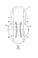
図1は生理用ナプキンの平面および横断面を模式的に示す。
図1において、ナプキンNは、透液性のトップシートTと、不透液性のバックシートBとの間に、コア(吸収体)Cが介挿されてなる。
【0011】
前記トップシートTおよびバックシートBの両側縁部は、熱融着されたヒートシール部Hsによって互いに接合されており、トップシートTおよびバックシートBは前記コアCを包んでいる。前記コアCは、パルプを解繊機(紛砕機)で繊維状に解繊(紛砕)したフラッフパルプや、該フラッフパルプに高吸水性ポリマー粒子(高分子吸収体)を混入したものを綿状に堆積させてなり、吸液性を有する。本実施形態のコアCは、前記フラッフパルプなどを包むティッシュペーパPを備えている。
なお、ティッシュペーパの有無やティッシュペーパがフラッフパルプを包む部分は、フラッフパルプの状態や、吸水性ポリマー粒子の量や種類などにより決定される。
【0012】
ナプキンNにはトップシートT側からコアCに向って窪んだ圧縮溝1が形成されている。前記圧縮溝1は、ナプキンNの長さ方向に沿って、かつ、ナプキンNにおけるトップシートTの両側縁T1の付近に互いに並列するように形成されており、この実施形態ではループ状に形成されている。なお、前記圧縮溝1の間の間隔はトップシートTの長さ方向の中間部分において狭くなっている。
該圧縮溝1が形成されていることにより、ナプキンNの女性局部への適合密着性が向上したり、あるいは、横漏れを防止する利点が得られる。
また、そのような効果を得るために、圧縮溝1は、コアCの中央部分付近が盛り上がるように形成されていてもよい。また、図1に示すナプキンにおいては、圧縮溝はループ状に形成されるが、ナプキンが複数本の圧縮溝を有していてもよい。
【0013】
前記圧縮溝1の底部には、図1(a)に示すように、多数の孔2が圧縮溝1に沿って所定のピッチで形成されている。これらの孔2は、図1(b)のトップシートTを貫通しているが、バックシートBまでは貫通していない。また、コアCの両面がティッシュペーパPで覆われている場合、トップシートT側のティッシュペーパPは、開口して貫通しているが、バックシートB側のティッシュペーパPは、開口していないのが好ましい。孔2がコアCを貫通して形成され、吸収性ポリマーがコアCから抜け落ちたとしても、ティッシュペーパPによってせき止められるからである。
なお、圧縮溝1および孔2の性状の詳細については後述する。
また、図1(b)においては、孔2の構造を分かり易くするために、圧縮溝1および孔2を誇張して描いてある。例えば、孔2がピンのように非常に細いものにより形成されている場合、孔2を目視することは難しいであろう。
【0014】
つぎに、前記ナプキンNの圧縮溝1を成形する成形装置について説明する。
図2(a)に示すように、成形装置は、第1加圧手段である加圧用の第1ロール10および第2加圧手段である第2ロール20を備えている。前記2つのロール10,20の間には、少なくともトップシートTの下(又は上)にコアCが積層された連続ウェブWが供給される。
【0015】
前記第1ロール10は、図2(a),(b)に示すように、圧縮溝1を形成するための凸条部11を備えている。該凸条部11の形状は、図1の圧縮溝1の形状に対応している。図2の前記凸条部11には、多数の突起12が突設されており、該突起12は、前記トップシートTおよびコアCに孔2を形成する。
【0016】
前記第2ロール20は、前記第1ロール10との間でトップシートTおよびコアCを押さえるものであり、本実施形態では、前記凸条部11に対応する箇所に逃孔21が形成されている。なお、凸条部11,突起12および逃孔21の部分は、図を分かり易くするために、拡大して(大きめに)図示している。
なお、突起12が逃孔21に入るように、第1ロール10と第2ロール20の距離が調整されていてもよい。そのような場合、突起12が第1ロール10と共に回転しても、突起12が逃孔21に当たらないように、逃孔21の形状は決定される。
また、第2ロール20は、第1ロール10の回転に応じて回転する。突起12と逃孔21との同期をとるためである。
【0017】
つぎに、圧縮溝1等の成形方法について説明する。
図2(a)のように、トップシートTおよびコアCからなる連続ウェブWは、一対のロール10,20間に供給されると、第1ロール10の凸条部11と第2ロール20との間で挟圧されて圧縮溝1(図1)が形成される。この際、圧縮溝1の底部は、挟圧されることにより、コアCの他の部分よりも締まって嵩密度が大きくなる。
【0018】
同時に、図3(a)のように、トップシートTおよび上側のティッシュペーパPには突起12が刺さり、図3(b)のトップシートTおよび上側のティッシュペーパPに貫通孔3が形成されると共に、該貫通孔3の下方には孔2が形成される。この際、図3(a)の突起12は、円錐状の針状突起12によってコアCを形成するフラッフパルプや高分子吸収体を左右に押し退けると共に、逃孔21に向ってコアCが逃げることで、突起12によりコアCが圧縮されないようになっている。したがって、孔2の底部(下部分)は圧縮溝1の底部(下部分)に対し、単位体積当たりの嵩密度が同等となる。その結果、圧縮溝1の底部の柔軟性が従来よりも高くなる。
【0019】
前記成形後、図3(b)または(c)のように、コアCの下にバックシートBが積層された後、周知のヒートシールやトリミング等がなされてナプキンNとなる。なお、突起12がティッシュペーパPまたはコアCを突き抜けないように、第1ロール10と第2ロール20の距離が調整されている場合、バックシートが積層された連続ウェブが前記成形装置に供給されてもよい。
【0020】
前記突起12によって形成される孔2としては、図3(b)のように、トップシートTおよび上側のティッシュペーパPに貫通孔3が形成され、かつ、トップシートTおよび上側のティッシュペーパPが孔2に沿った形状となっておらずコアCを構成するフラッフパルプやポリマー粒子が左右に押し退けられた状態であってもよいし、図3(c)のように、トップシートTおよび上側のティッシュペーパPが孔2に沿った形状に成形されていてもよい。さらに、トップシートTとして伸縮性の高い素材を用いれば、トップシートTに貫通孔が形成されない場合もある。
【0021】
前述のように、孔2の底部の嵩密度が大きくならないようにするためには前記図3(a)の突起12の先端を尖った形状とするのが好ましいが、若干の丸みがあってもよい。また、突起12は、円錐形の他に多角錐などとしてもよい。更に、図4の変形例に示すように、孔は圧縮溝1に直交する短い溝状の孔2であってもよい。
【0022】
図3(c)において、ナプキンNの厚さをt、トップシートTから孔2の底部までの深さをdとすると、深さdは一般に厚さtの30%〜99%に設定され、好ましくは50%〜95%、より好ましくは70%〜95%に設定される。
【0023】
なお、図2(b)の凸状部11の幅Wiは、1mm〜15mm程度に設定され、凸状部11の幅Wiが広い場合には、図2(c)のように、突起12を複数列にしてもよい。また、突起12同士の間隔は、一般に0.5mm〜3.0mmに設定する。
【0024】
図5はナプキンNの第2実施形態を示す。
この図に示すように、ナプキンNのバックシートBはその両側縁から側方に向かって突出する一対の翼状部B1を有している。圧縮溝1は、ナプキンNの長さ方向に沿って、かつ、ナプキンNにおける前記一対の翼状部B1の内側に互いに並列するように形成されている。前記圧縮溝1,1間の間隔は前記2つの翼状部B1の中心をナプキンNの幅方向に横切る箇所の方が、前記2つの翼状部B1の付け根B11を前記ナプキンNの幅方向に横切る箇所よりも狭くなっている。すなわち、D2>D1に設定されている。
【0025】
図6は他の実施形態である成形装置を示す図である。
図6に示す成形装置は、第1ロール10Aおよび第3ロール30Aを有する第1加圧手段と、第2ロール20を有する第2加圧手段を備えている。第1ロール10Aは圧縮溝1を形成するための凸条部11を有し、第3ロール30Aは圧縮溝1に孔2を開ける突起12を有している。また、図6の第2ロール20は、図2(a)の第2ロール20と同様の逃孔21を有している。第2ロール20は、第1ロール10A及び第3ロール30Aと同じタイミングで回転する。
図6に示す成形装置は、第1ロール10Aによって連続ウェブWに圧縮溝1を形成し、該圧縮溝1に第3ロール30Aによって孔2を形成する。
【0026】
なお、第2ロール20は、第2ロール20を平面上に展開したような構成であってもよい。たとえば、厚みのあるベルトに多数の逃孔21を設け、第1ロール10等がベルトに接触する部分をベルトの下から支える構造としてもよい。同様のことが、図2(a)に示す成形装置についてもいえる。
【0027】
以上のとおり、図面を参照しながら好適な実施形態を説明したが、当業者であれば、本明細書を見て、自明な範囲で種々の変更および修正を容易に想定するであろう。
たとえば、突起12の形状は、錐状に限定されず、円錐状の尖った先端部と円柱状の基端部とが一体となった形状としてもよい。
したがって、そのような変更および修正は、請求の範囲から定まる本発明の範囲内のものと解釈される。
【0028】
【発明の効果】
以上説明したように、本発明によれば、圧縮溝の底部に柔らかな複数の孔を形成したので、吸収体における圧縮溝の底部が孔で曲がり易くなり、そのため、着用物品の柔軟性が高くなる。
【0029】
また、本発明の製造装置によれば、第1ロールの凸状部に突起を突設したので圧縮溝に対し孔の位置がズレるのを防止でき、着用物品が精度良く仕上がる。
【0030】
また、前記突起が嵌まり込む逃孔を第2ロールに設ければ、着用物品を傷めることなく、吸収体に孔を形成することができる。
【図面の簡単な説明】
【図1】本発明の第1実施形態を示すナプキンの平面図および拡大横断面図である。
【図2】(a)は圧縮溝および孔の成形装置を示す概略構成図、(b)は凸状部および突起を示す斜視図である。
【図3】孔の成形方法および構造を示す拡大断面図である。
【図4】孔の他の例を示す拡大斜視図である。
【図5】第2実施形態を示すナプキンの平面図である。
【図6】圧縮溝および孔の成形装置の他の実施形態を示す概略構成図である。
【符号の説明】
1:圧縮溝
2:孔
10,10A,30A:第1加圧手段
11:凸状部
12:突起
20:第2加圧手段
21:逃孔
B:バックシート(不透液性シート)
B1:翼状部
B11:翼状部の付け根
C:コア(吸収体)
N:ナプキン(着用物品)
T:トップシート(透液性シート)
T1:トップシートの両側縁[0001]
BACKGROUND OF THE INVENTION
The present invention mainly relates to disposable wearing articles such as sanitary napkins, incontinence pads, diapers, and pants, and an apparatus for manufacturing the same.
[0002]
[Prior art]
In recent years, a napkin having a compressed groove formed on the top sheet (liquid permeable sheet) side has been used (for example, Japanese Utility Model Publication No. 5-39691, Japanese Patent No. 3,053,561, Japanese Patent Application Laid-Open No. 2000-14701). ). Such a compressed groove is useful for preventing side leakage.
[0003]
[Problems to be solved by the invention]
However, the said pressing groove is formed by squeezing the surface of a napkin, Therefore, the softness | flexibility of a wearing article falls, for example, a wear feeling and a fall of a fitting property are caused.
[0004]
Accordingly, an object of the present invention is to improve the flexibility of a wearing article provided with a compressed groove.
Moreover, the other objective of this invention is to provide the manufacturing apparatus of this wearing article.
[0005]
[Means for Solving the Problems]
In order to achieve the object, the present wearing article includes a liquid-permeable sheet, a liquid-impermeable sheet, and an absorbent body sandwiched between the liquid-permeable sheet and the liquid-impermeable sheet. It is a worn article, and the worn article is formed with a compressed groove that is recessed from the liquid-permeable sheet side toward the absorber, and the bottom of the compressed groove in the absorbent body penetrates the liquid-impermeable sheet. A plurality of holes that are not formed are formed.
[0006]
In the present invention, the “compressed groove” refers to a groove formed by compressing the absorber in the thickness direction. The “compressed groove” only needs to be formed in at least one strip, but in the case of a napkin, two compressed grooves are generally formed in parallel along the length direction.
[0007]
The lower part of the “hole” in the absorbent body has the same degree of compression (bulk density) as the other lower part of the compressed groove, or a smaller degree of compression (bulk density) than the other lower part. Is preferred. This is because if the degree of compression of the lower part of the “hole” in the absorber is large, the bending rigidity in the part becomes large and the flexibility is lowered. As an extreme example, when the hole penetrates the absorber, the lower part of the hole does not exist, and the degree of compression becomes zero.
[0008]
The “hole” may not penetrate the absorber or may penetrate the absorber.
[0009]
On the other hand, in order to manufacture the wearing article of the present invention, a first pressurizing unit for pressurization provided with a ridge for forming a compression groove in the liquid-permeable sheet and the absorbent body, and the first pressurizing unit A second pressurizing unit for pressurizing the liquid-permeable sheet and the absorber between the first and second pressurizing units, and a plurality of holes forming the holes in the liquid-permeable sheet and the absorber. It is possible to use a manufacturing apparatus in which the protrusions are projected.
[0010]
DETAILED DESCRIPTION OF THE INVENTION
Hereinafter, embodiments of the present invention will be described with reference to the drawings.
FIG. 1 schematically shows a plane and a cross section of a sanitary napkin.
In FIG. 1, the napkin N includes a core (absorber) C interposed between a liquid-permeable top sheet T and a liquid-impermeable back sheet B.
[0011]
Both side edges of the top sheet T and the back sheet B are joined to each other by a heat-sealed heat seal portion Hs, and the top sheet T and the back sheet B wrap around the core C. The core C is a fluff pulp obtained by pulverizing (pulverizing) pulp into a fiber using a defibrator (pulverizer) or a mixture of superabsorbent polymer particles (polymer absorber) mixed with the fluff pulp. It has a liquid-absorbing property. The core C of the present embodiment includes a tissue paper P that wraps the fluff pulp and the like.
The presence or absence of tissue paper and the portion where tissue paper wraps fluff pulp are determined by the state of fluff pulp, the amount and type of water-absorbing polymer particles, and the like.
[0012]
The napkin N is formed with a
By forming the
In order to obtain such an effect, the
[0013]
As shown in FIG. 1A, a large number of
Details of the properties of the
Further, in FIG. 1B, the
[0014]
Next, a forming apparatus for forming the
As shown in FIG. 2A, the molding apparatus includes a
[0015]
The said
[0016]
The
The distance between the
Further, the
[0017]
Next, a method for forming the
As shown in FIG. 2A, when the continuous web W composed of the top sheet T and the core C is supplied between the pair of
[0018]
At the same time, as shown in FIG. 3A, the
[0019]
After the molding, as shown in FIG. 3 (b) or 3 (c), a back sheet B is laminated under the core C, and then a known heat seal, trimming or the like is performed to form a napkin N. When the distance between the
[0020]
As the
[0021]
As described above, in order to prevent the bulk density at the bottom of the
[0022]
In FIG. 3 (c), assuming that the thickness of the napkin N is t and the depth from the top sheet T to the bottom of the
[0023]
The width Wi of the
[0024]
FIG. 5 shows a second embodiment of the napkin N.
As shown in this figure, the backsheet B of the napkin N has a pair of wing-like parts B1 protruding from the both side edges toward the side. The
[0025]
FIG. 6 is a view showing a molding apparatus according to another embodiment.
The molding apparatus shown in FIG. 6 includes a first pressure unit having a
The forming apparatus shown in FIG. 6 forms the
[0026]
The
[0027]
As described above, the preferred embodiments have been described with reference to the drawings. However, those skilled in the art will readily understand various changes and modifications within the obvious scope by looking at the present specification.
For example, the shape of the
Accordingly, such changes and modifications are to be construed as within the scope of the present invention as defined by the claims.
[0028]
【The invention's effect】
As described above, according to the present invention, since the plurality of soft holes are formed at the bottom of the compressed groove, the bottom of the compressed groove in the absorbent body is easily bent by the hole, and thus the flexibility of the wearing article is high. Become.
[0029]
Moreover, according to the manufacturing apparatus of this invention, since the protrusion was provided in the convex part of the 1st roll, it can prevent that the position of a hole shifts | deviates with respect to a compression groove, and a wear article is finished with sufficient precision.
[0030]
Moreover, if an escape hole into which the protrusion fits is provided in the second roll, the hole can be formed in the absorbent body without damaging the worn article.
[Brief description of the drawings]
FIG. 1 is a plan view and an enlarged cross-sectional view of a napkin showing a first embodiment of the present invention.
FIG. 2A is a schematic configuration diagram showing a compression groove and hole forming apparatus, and FIG. 2B is a perspective view showing convex portions and protrusions.
FIG. 3 is an enlarged sectional view showing a hole forming method and structure.
FIG. 4 is an enlarged perspective view showing another example of a hole.
FIG. 5 is a plan view of a napkin showing a second embodiment.
FIG. 6 is a schematic configuration diagram showing another embodiment of a compression groove and hole forming apparatus.
[Explanation of symbols]
1: compression groove 2:
B1: Wing B11: Wing base C: Core (absorber)
N: Napkin (wearing article)
T: Top sheet (liquid permeable sheet)
T1: Both side edges of the top sheet
Claims (4)
前記着用物品には前記透液性シート側から前記吸収体に向って窪んだ圧縮溝が形成され、
前記吸収体における圧縮溝の底部には、前記透液性シートを貫通し、かつ、前記不透液性シートを貫通しない複数の孔が形成され、
前記吸収体における前記孔の下部分は、前記孔が針状突起により形成されていることで前記圧縮溝の他の下部分に対し同程度の嵩密度又は前記他の下部分よりも小さな嵩密度である着用物品。A liquid-permeable sheet, a liquid-impervious sheet, and a wearing article comprising an absorbent body sandwiched between the liquid-permeable sheet and the liquid-impermeable sheet,
The wearing article is formed with a compressed groove that is recessed from the liquid-permeable sheet side toward the absorber,
A plurality of holes that penetrates the liquid-permeable sheet and does not penetrate the liquid-impermeable sheet are formed at the bottom of the compressed groove in the absorbent body,
The lower part of the hole in the absorbent body has the same or lower bulk density than the other lower part with respect to the other lower part of the compressed groove because the hole is formed by needle-like protrusions. Wearing articles that are
前記圧縮溝は、前記着用物品の長さ方向に沿って、かつ、前記着用物品における透液性シートの両側縁の付近に互いに並列するように形成され、
前記圧縮溝の間の間隔が前記透液性シートの長さ方向の中間部分において狭くなっている着用物品。In claim 1,
The compressed groove is formed along the length direction of the wearing article and in parallel with each other in the vicinity of both side edges of the liquid-permeable sheet in the wearing article,
A wearing article in which a space between the compressed grooves is narrow in an intermediate portion in a length direction of the liquid-permeable sheet.
前記着用物品は前記着用物品の両側縁から側方に向って突出する一対の翼状部を有し、
前記圧縮溝は、前記着用物品の長さ方向に沿って、かつ、前記着用物品における前記一対の翼状部の内側に互いに並列するように形成され、
前記圧縮溝間の間隔は前記2つの翼状部の中心を前記着用物品の幅方向に横切る箇所の方が、前記2つの翼状部の付け根を前記着用物品の幅方向に横切る箇所よりも狭くなっている着用物品。In claim 1,
The wearing article has a pair of wings protruding from the side edges of the wearing article to the side,
The compressed groove is formed so as to be parallel to each other along the length direction of the wearing article and inside the pair of wing-shaped parts in the wearing article,
The space between the compressed grooves is narrower at a location where the center of the two wings crosses the width of the wearing article than at a location where the root of the two wings crosses the width of the wearing article. Wearing articles.
透液性シートおよび吸収体に圧縮溝を形成するための凸条部を備えた加圧用の第1加圧手段と、
前記第1加圧手段との間で前記透液性シートおよび吸収体を押さえる加圧用の第2加圧手段とを備え、
前記第1加圧手段には、前記透液性シートに貫通孔を形成すると共に、前記貫通孔に対応する部分の吸収体が圧縮されないように前記吸収体を押し退けて前記吸収体に孔を形成する複数の針状突起が前記凸条部に突設され、
前記加圧用の第2加圧手段には、前記複数の針状突起が嵌り込むことができる逃孔が形成されている着用物品の製造装置。A wearing article manufacturing apparatus for manufacturing a wearing article,
A first pressurizing means for pressurization provided with a ridge for forming a compression groove in the liquid-permeable sheet and the absorbent body;
A second pressurizing unit for pressurizing the liquid-permeable sheet and the absorbent body with the first pressurizing unit,
In the first pressurizing means, a through hole is formed in the liquid-permeable sheet, and a hole is formed in the absorbent body by pushing away the absorbent body so that the absorbent body corresponding to the through hole is not compressed. A plurality of needle-like protrusions projecting from the ridge ,
The apparatus for manufacturing a worn article , wherein the second pressurizing unit for pressurization is formed with an escape hole into which the plurality of needle-like protrusions can be fitted .
Priority Applications (1)
| Application Number | Priority Date | Filing Date | Title |
|---|---|---|---|
| JP2000319502A JP3676219B2 (en) | 2000-10-19 | 2000-10-19 | Wearing article and manufacturing apparatus thereof |
Applications Claiming Priority (1)
| Application Number | Priority Date | Filing Date | Title |
|---|---|---|---|
| JP2000319502A JP3676219B2 (en) | 2000-10-19 | 2000-10-19 | Wearing article and manufacturing apparatus thereof |
Publications (2)
| Publication Number | Publication Date |
|---|---|
| JP2002119539A JP2002119539A (en) | 2002-04-23 |
| JP3676219B2 true JP3676219B2 (en) | 2005-07-27 |
Family
ID=18797954
Family Applications (1)
| Application Number | Title | Priority Date | Filing Date |
|---|---|---|---|
| JP2000319502A Expired - Fee Related JP3676219B2 (en) | 2000-10-19 | 2000-10-19 | Wearing article and manufacturing apparatus thereof |
Country Status (1)
| Country | Link |
|---|---|
| JP (1) | JP3676219B2 (en) |
Cited By (32)
| Publication number | Priority date | Publication date | Assignee | Title |
|---|---|---|---|---|
| US9649232B2 (en) | 2011-06-10 | 2017-05-16 | The Procter & Gamble Company | Disposable diaper having reduced absorbent core to backsheet gluing |
| US9668926B2 (en) | 2011-06-10 | 2017-06-06 | The Procter & Gamble Company | Method and apparatus for making absorbent structures with absorbent material |
| US9713556B2 (en) | 2012-12-10 | 2017-07-25 | The Procter & Gamble Company | Absorbent core with high superabsorbent material content |
| US9713557B2 (en) | 2012-12-10 | 2017-07-25 | The Procter & Gamble Company | Absorbent article with high absorbent material content |
| US9763835B2 (en) | 2003-02-12 | 2017-09-19 | The Procter & Gamble Company | Comfortable diaper |
| US9789011B2 (en) | 2013-08-27 | 2017-10-17 | The Procter & Gamble Company | Absorbent articles with channels |
| US9789009B2 (en) | 2013-12-19 | 2017-10-17 | The Procter & Gamble Company | Absorbent articles having channel-forming areas and wetness indicator |
| US9974699B2 (en) | 2011-06-10 | 2018-05-22 | The Procter & Gamble Company | Absorbent core for disposable absorbent articles |
| US9987176B2 (en) | 2013-08-27 | 2018-06-05 | The Procter & Gamble Company | Absorbent articles with channels |
| US10004647B2 (en) | 2009-12-02 | 2018-06-26 | The Procter & Gamble Company | Apparatus and method for transferring particulate material |
| US10022280B2 (en) | 2012-12-10 | 2018-07-17 | The Procter & Gamble Company | Absorbent article with high absorbent material content |
| US10071002B2 (en) | 2013-06-14 | 2018-09-11 | The Procter & Gamble Company | Absorbent article and absorbent core forming channels when wet |
| US10130527B2 (en) | 2013-09-19 | 2018-11-20 | The Procter & Gamble Company | Absorbent cores having material free areas |
| US10130525B2 (en) | 2011-06-10 | 2018-11-20 | The Procter & Gamble Company | Absorbent structure for absorbent articles |
| US10137039B2 (en) | 2013-12-19 | 2018-11-27 | The Procter & Gamble Company | Absorbent cores having channel-forming areas and C-wrap seals |
| US10149788B2 (en) | 2011-06-10 | 2018-12-11 | The Procter & Gamble Company | Disposable diapers |
| US10245188B2 (en) | 2011-06-10 | 2019-04-02 | The Procter & Gamble Company | Method and apparatus for making absorbent structures with absorbent material |
| US10292875B2 (en) | 2013-09-16 | 2019-05-21 | The Procter & Gamble Company | Absorbent articles with channels and signals |
| US10322040B2 (en) | 2015-03-16 | 2019-06-18 | The Procter & Gamble Company | Absorbent articles with improved cores |
| US10449097B2 (en) | 2012-11-13 | 2019-10-22 | The Procter & Gamble Company | Absorbent articles with channels and signals |
| US10470948B2 (en) | 2003-02-12 | 2019-11-12 | The Procter & Gamble Company | Thin and dry diaper |
| US10507144B2 (en) | 2015-03-16 | 2019-12-17 | The Procter & Gamble Company | Absorbent articles with improved strength |
| US10543129B2 (en) | 2015-05-29 | 2020-01-28 | The Procter & Gamble Company | Absorbent articles having channels and wetness indicator |
| US10561546B2 (en) | 2011-06-10 | 2020-02-18 | The Procter & Gamble Company | Absorbent structure for absorbent articles |
| US10632029B2 (en) | 2015-11-16 | 2020-04-28 | The Procter & Gamble Company | Absorbent cores having material free areas |
| US10639215B2 (en) | 2012-12-10 | 2020-05-05 | The Procter & Gamble Company | Absorbent articles with channels and/or pockets |
| US10736795B2 (en) | 2015-05-12 | 2020-08-11 | The Procter & Gamble Company | Absorbent article with improved core-to-backsheet adhesive |
| US10842690B2 (en) | 2016-04-29 | 2020-11-24 | The Procter & Gamble Company | Absorbent core with profiled distribution of absorbent material |
| US11090199B2 (en) | 2014-02-11 | 2021-08-17 | The Procter & Gamble Company | Method and apparatus for making an absorbent structure comprising channels |
| US11123240B2 (en) | 2016-04-29 | 2021-09-21 | The Procter & Gamble Company | Absorbent core with transversal folding lines |
| US11207220B2 (en) | 2013-09-16 | 2021-12-28 | The Procter & Gamble Company | Absorbent articles with channels and signals |
| US11510829B2 (en) | 2014-05-27 | 2022-11-29 | The Procter & Gamble Company | Absorbent core with absorbent material pattern |
Families Citing this family (11)
| Publication number | Priority date | Publication date | Assignee | Title |
|---|---|---|---|---|
| JP4180866B2 (en) * | 2002-09-09 | 2008-11-12 | ユニ・チャーム株式会社 | Absorbent article having elastic restoring portion and method for producing the same |
| US7550646B2 (en) | 2002-09-09 | 2009-06-23 | Uni-Charm Corporation | Absorbent article with resilient portion and method for manufacturing the same |
| JP4390445B2 (en) * | 2002-12-05 | 2009-12-24 | ユニ・チャーム株式会社 | Long absorbent article |
| JP4863697B2 (en) * | 2005-11-08 | 2012-01-25 | 花王株式会社 | Composite sheet, manufacturing method and apparatus |
| JP4928181B2 (en) * | 2006-07-10 | 2012-05-09 | 大王製紙株式会社 | Perforated sheet manufacturing equipment |
| JP2008264077A (en) * | 2007-04-17 | 2008-11-06 | Uni Charm Corp | Absorbent article and manufacturing method of absorbent article |
| JP5154133B2 (en) * | 2007-04-17 | 2013-02-27 | ユニ・チャーム株式会社 | Absorber and method for producing the absorber |
| JP5765910B2 (en) * | 2010-09-30 | 2015-08-19 | ユニ・チャーム株式会社 | Absorbent articles |
| JP2014079566A (en) * | 2012-09-30 | 2014-05-08 | Uni Charm Corp | Absorbent article |
| JP6138864B2 (en) * | 2015-06-30 | 2017-05-31 | ユニ・チャーム株式会社 | Absorbent articles |
| JP6932887B2 (en) * | 2017-06-20 | 2021-09-08 | 日本製紙クレシア株式会社 | Absorbent article for light incontinence |
Family Cites Families (4)
| Publication number | Priority date | Publication date | Assignee | Title |
|---|---|---|---|---|
| JP3088874B2 (en) * | 1993-05-18 | 2000-09-18 | 花王株式会社 | Method and apparatus for manufacturing perforated sheet |
| JP3053561B2 (en) * | 1995-10-19 | 2000-06-19 | ユニ・チャーム株式会社 | Sanitary napkin |
| JP3568146B2 (en) * | 1998-07-03 | 2004-09-22 | 花王株式会社 | Method and apparatus for manufacturing absorbent article |
| JP3522640B2 (en) * | 1999-04-27 | 2004-04-26 | 花王株式会社 | Equipment for manufacturing absorbent articles |
-
2000
- 2000-10-19 JP JP2000319502A patent/JP3676219B2/en not_active Expired - Fee Related
Cited By (56)
| Publication number | Priority date | Publication date | Assignee | Title |
|---|---|---|---|---|
| US11135096B2 (en) | 2003-02-12 | 2021-10-05 | The Procter & Gamble Company | Comfortable diaper |
| US10470948B2 (en) | 2003-02-12 | 2019-11-12 | The Procter & Gamble Company | Thin and dry diaper |
| US10660800B2 (en) | 2003-02-12 | 2020-05-26 | The Procter & Gamble Company | Comfortable diaper |
| US11793682B2 (en) | 2003-02-12 | 2023-10-24 | The Procter & Gamble Company | Thin and dry diaper |
| US9763835B2 (en) | 2003-02-12 | 2017-09-19 | The Procter & Gamble Company | Comfortable diaper |
| US11234868B2 (en) | 2003-02-12 | 2022-02-01 | The Procter & Gamble Company | Comfortable diaper |
| US10004647B2 (en) | 2009-12-02 | 2018-06-26 | The Procter & Gamble Company | Apparatus and method for transferring particulate material |
| US11135105B2 (en) | 2011-06-10 | 2021-10-05 | The Procter & Gamble Company | Absorbent structure for absorbent articles |
| US10813794B2 (en) | 2011-06-10 | 2020-10-27 | The Procter & Gamble Company | Method and apparatus for making absorbent structures with absorbent material |
| US11602467B2 (en) | 2011-06-10 | 2023-03-14 | The Procter & Gamble Company | Absorbent structure for absorbent articles |
| US10517777B2 (en) | 2011-06-10 | 2019-12-31 | The Procter & Gamble Company | Disposable diaper having first and second absorbent structures and channels |
| US11110011B2 (en) | 2011-06-10 | 2021-09-07 | The Procter & Gamble Company | Absorbent structure for absorbent articles |
| US10893987B2 (en) | 2011-06-10 | 2021-01-19 | The Procter & Gamble Company | Disposable diapers with main channels and secondary channels |
| US10130525B2 (en) | 2011-06-10 | 2018-11-20 | The Procter & Gamble Company | Absorbent structure for absorbent articles |
| US9974699B2 (en) | 2011-06-10 | 2018-05-22 | The Procter & Gamble Company | Absorbent core for disposable absorbent articles |
| US10149788B2 (en) | 2011-06-10 | 2018-12-11 | The Procter & Gamble Company | Disposable diapers |
| US10245188B2 (en) | 2011-06-10 | 2019-04-02 | The Procter & Gamble Company | Method and apparatus for making absorbent structures with absorbent material |
| US11911250B2 (en) | 2011-06-10 | 2024-02-27 | The Procter & Gamble Company | Absorbent structure for absorbent articles |
| US9649232B2 (en) | 2011-06-10 | 2017-05-16 | The Procter & Gamble Company | Disposable diaper having reduced absorbent core to backsheet gluing |
| US10561546B2 (en) | 2011-06-10 | 2020-02-18 | The Procter & Gamble Company | Absorbent structure for absorbent articles |
| US9668926B2 (en) | 2011-06-10 | 2017-06-06 | The Procter & Gamble Company | Method and apparatus for making absorbent structures with absorbent material |
| US10449097B2 (en) | 2012-11-13 | 2019-10-22 | The Procter & Gamble Company | Absorbent articles with channels and signals |
| US10639215B2 (en) | 2012-12-10 | 2020-05-05 | The Procter & Gamble Company | Absorbent articles with channels and/or pockets |
| US9713556B2 (en) | 2012-12-10 | 2017-07-25 | The Procter & Gamble Company | Absorbent core with high superabsorbent material content |
| US10022280B2 (en) | 2012-12-10 | 2018-07-17 | The Procter & Gamble Company | Absorbent article with high absorbent material content |
| US9713557B2 (en) | 2012-12-10 | 2017-07-25 | The Procter & Gamble Company | Absorbent article with high absorbent material content |
| US10071002B2 (en) | 2013-06-14 | 2018-09-11 | The Procter & Gamble Company | Absorbent article and absorbent core forming channels when wet |
| US11612523B2 (en) | 2013-08-27 | 2023-03-28 | The Procter & Gamble Company | Absorbent articles with channels |
| US10335324B2 (en) | 2013-08-27 | 2019-07-02 | The Procter & Gamble Company | Absorbent articles with channels |
| US9789011B2 (en) | 2013-08-27 | 2017-10-17 | The Procter & Gamble Company | Absorbent articles with channels |
| US11406544B2 (en) | 2013-08-27 | 2022-08-09 | The Procter & Gamble Company | Absorbent articles with channels |
| US11759376B2 (en) | 2013-08-27 | 2023-09-19 | The Procter & Gamble Company | Absorbent articles with channels |
| US9987176B2 (en) | 2013-08-27 | 2018-06-05 | The Procter & Gamble Company | Absorbent articles with channels |
| US10736794B2 (en) | 2013-08-27 | 2020-08-11 | The Procter & Gamble Company | Absorbent articles with channels |
| US10765567B2 (en) | 2013-08-27 | 2020-09-08 | The Procter & Gamble Company | Absorbent articles with channels |
| US11207220B2 (en) | 2013-09-16 | 2021-12-28 | The Procter & Gamble Company | Absorbent articles with channels and signals |
| US10292875B2 (en) | 2013-09-16 | 2019-05-21 | The Procter & Gamble Company | Absorbent articles with channels and signals |
| US11154437B2 (en) | 2013-09-19 | 2021-10-26 | The Procter & Gamble Company | Absorbent cores having material free areas |
| US11944526B2 (en) | 2013-09-19 | 2024-04-02 | The Procter & Gamble Company | Absorbent cores having material free areas |
| US10130527B2 (en) | 2013-09-19 | 2018-11-20 | The Procter & Gamble Company | Absorbent cores having material free areas |
| US10137039B2 (en) | 2013-12-19 | 2018-11-27 | The Procter & Gamble Company | Absorbent cores having channel-forming areas and C-wrap seals |
| US10675187B2 (en) | 2013-12-19 | 2020-06-09 | The Procter & Gamble Company | Absorbent articles having channel-forming areas and wetness indicator |
| US11191679B2 (en) | 2013-12-19 | 2021-12-07 | The Procter & Gamble Company | Absorbent articles having channel-forming areas and wetness indicator |
| US10828206B2 (en) | 2013-12-19 | 2020-11-10 | Procter & Gamble Company | Absorbent articles having channel-forming areas and wetness indicator |
| US9789009B2 (en) | 2013-12-19 | 2017-10-17 | The Procter & Gamble Company | Absorbent articles having channel-forming areas and wetness indicator |
| US11090199B2 (en) | 2014-02-11 | 2021-08-17 | The Procter & Gamble Company | Method and apparatus for making an absorbent structure comprising channels |
| US11510829B2 (en) | 2014-05-27 | 2022-11-29 | The Procter & Gamble Company | Absorbent core with absorbent material pattern |
| US10322040B2 (en) | 2015-03-16 | 2019-06-18 | The Procter & Gamble Company | Absorbent articles with improved cores |
| US10507144B2 (en) | 2015-03-16 | 2019-12-17 | The Procter & Gamble Company | Absorbent articles with improved strength |
| US10736795B2 (en) | 2015-05-12 | 2020-08-11 | The Procter & Gamble Company | Absorbent article with improved core-to-backsheet adhesive |
| US11918445B2 (en) | 2015-05-12 | 2024-03-05 | The Procter & Gamble Company | Absorbent article with improved core-to-backsheet adhesive |
| US11497657B2 (en) | 2015-05-29 | 2022-11-15 | The Procter & Gamble Company | Absorbent articles having channels and wetness indicator |
| US10543129B2 (en) | 2015-05-29 | 2020-01-28 | The Procter & Gamble Company | Absorbent articles having channels and wetness indicator |
| US10632029B2 (en) | 2015-11-16 | 2020-04-28 | The Procter & Gamble Company | Absorbent cores having material free areas |
| US11123240B2 (en) | 2016-04-29 | 2021-09-21 | The Procter & Gamble Company | Absorbent core with transversal folding lines |
| US10842690B2 (en) | 2016-04-29 | 2020-11-24 | The Procter & Gamble Company | Absorbent core with profiled distribution of absorbent material |
Also Published As
| Publication number | Publication date |
|---|---|
| JP2002119539A (en) | 2002-04-23 |
Similar Documents
| Publication | Publication Date | Title |
|---|---|---|
| JP3676219B2 (en) | Wearing article and manufacturing apparatus thereof | |
| US10766186B2 (en) | Method of making an absorbent core for disposable absorbent article | |
| JP4124322B2 (en) | Absorbent articles | |
| JP4058281B2 (en) | Absorbent articles | |
| JP3467376B2 (en) | Absorbent articles for body fluid treatment | |
| KR100370503B1 (en) | 3-Division Physiology | |
| US9655788B2 (en) | Absorbent article having traverse reinforcing element | |
| JP3408078B2 (en) | Absorbent articles | |
| EP1402863B1 (en) | Thin comfortable sanitary napkin having reduced bunching | |
| US8502013B2 (en) | Disposable absorbent article | |
| JP3053561B2 (en) | Sanitary napkin | |
| US7857799B2 (en) | Absorbent article | |
| JP5306753B2 (en) | Body fluid absorbent article | |
| US20160338879A1 (en) | Absorbent core for disposable absorbent article | |
| EP2117493B1 (en) | Method of making of absorbent core | |
| KR100699190B1 (en) | Thin sanitary napkin capable of controlled deformation when in use | |
| WO2008062872A1 (en) | Absorptive article and method of producing the same | |
| US20080221542A1 (en) | Absorbent article | |
| JP2003033397A (en) | Absorbing article | |
| JP2002512849A (en) | How to individually package three-dimensional absorbent products | |
| KR20010024679A (en) | Compound sanitary napkin having flaps and zone of extensibility | |
| TW200302708A (en) | Absorbent body and absorbent article having the absorbent body | |
| JP2002165830A (en) | Surface sheet for absorptive article | |
| JP2001340382A (en) | Absorbable article | |
| KR100822922B1 (en) | Sanitary napkin for clean body benefit |
Legal Events
| Date | Code | Title | Description |
|---|---|---|---|
| A131 | Notification of reasons for refusal |
Free format text: JAPANESE INTERMEDIATE CODE: A131 Effective date: 20031224 |
|
| A521 | Written amendment |
Free format text: JAPANESE INTERMEDIATE CODE: A523 Effective date: 20040220 |
|
| A131 | Notification of reasons for refusal |
Free format text: JAPANESE INTERMEDIATE CODE: A131 Effective date: 20050201 |
|
| A521 | Written amendment |
Free format text: JAPANESE INTERMEDIATE CODE: A523 Effective date: 20050322 |
|
| TRDD | Decision of grant or rejection written | ||
| A01 | Written decision to grant a patent or to grant a registration (utility model) |
Free format text: JAPANESE INTERMEDIATE CODE: A01 Effective date: 20050426 |
|
| A61 | First payment of annual fees (during grant procedure) |
Free format text: JAPANESE INTERMEDIATE CODE: A61 Effective date: 20050427 |
|
| R150 | Certificate of patent or registration of utility model |
Ref document number: 3676219 Country of ref document: JP Free format text: JAPANESE INTERMEDIATE CODE: R150 Free format text: JAPANESE INTERMEDIATE CODE: R150 |
|
| FPAY | Renewal fee payment (event date is renewal date of database) |
Free format text: PAYMENT UNTIL: 20080513 Year of fee payment: 3 |
|
| FPAY | Renewal fee payment (event date is renewal date of database) |
Free format text: PAYMENT UNTIL: 20090513 Year of fee payment: 4 |
|
| R250 | Receipt of annual fees |
Free format text: JAPANESE INTERMEDIATE CODE: R250 |
|
| FPAY | Renewal fee payment (event date is renewal date of database) |
Free format text: PAYMENT UNTIL: 20100513 Year of fee payment: 5 |
|
| R250 | Receipt of annual fees |
Free format text: JAPANESE INTERMEDIATE CODE: R250 |
|
| FPAY | Renewal fee payment (event date is renewal date of database) |
Free format text: PAYMENT UNTIL: 20100513 Year of fee payment: 5 |
|
| FPAY | Renewal fee payment (event date is renewal date of database) |
Free format text: PAYMENT UNTIL: 20110513 Year of fee payment: 6 |
|
| R250 | Receipt of annual fees |
Free format text: JAPANESE INTERMEDIATE CODE: R250 |
|
| FPAY | Renewal fee payment (event date is renewal date of database) |
Free format text: PAYMENT UNTIL: 20110513 Year of fee payment: 6 |
|
| FPAY | Renewal fee payment (event date is renewal date of database) |
Free format text: PAYMENT UNTIL: 20120513 Year of fee payment: 7 |
|
| R250 | Receipt of annual fees |
Free format text: JAPANESE INTERMEDIATE CODE: R250 |
|
| FPAY | Renewal fee payment (event date is renewal date of database) |
Free format text: PAYMENT UNTIL: 20120513 Year of fee payment: 7 |
|
| FPAY | Renewal fee payment (event date is renewal date of database) |
Free format text: PAYMENT UNTIL: 20130513 Year of fee payment: 8 |
|
| R250 | Receipt of annual fees |
Free format text: JAPANESE INTERMEDIATE CODE: R250 |
|
| R250 | Receipt of annual fees |
Free format text: JAPANESE INTERMEDIATE CODE: R250 |
|
| R250 | Receipt of annual fees |
Free format text: JAPANESE INTERMEDIATE CODE: R250 |
|
| R250 | Receipt of annual fees |
Free format text: JAPANESE INTERMEDIATE CODE: R250 |
|
| R250 | Receipt of annual fees |
Free format text: JAPANESE INTERMEDIATE CODE: R250 |
|
| R250 | Receipt of annual fees |
Free format text: JAPANESE INTERMEDIATE CODE: R250 |
|
| R250 | Receipt of annual fees |
Free format text: JAPANESE INTERMEDIATE CODE: R250 |
|
| LAPS | Cancellation because of no payment of annual fees |