JP3676144B2 - Signal recording or playback device - Google Patents
Signal recording or playback device Download PDFInfo
- Publication number
- JP3676144B2 JP3676144B2 JP28259599A JP28259599A JP3676144B2 JP 3676144 B2 JP3676144 B2 JP 3676144B2 JP 28259599 A JP28259599 A JP 28259599A JP 28259599 A JP28259599 A JP 28259599A JP 3676144 B2 JP3676144 B2 JP 3676144B2
- Authority
- JP
- Japan
- Prior art keywords
- cabinet
- lid
- mechanism deck
- deck
- damper
- Prior art date
- Legal status (The legal status is an assumption and is not a legal conclusion. Google has not performed a legal analysis and makes no representation as to the accuracy of the status listed.)
- Expired - Fee Related
Links
Images


Landscapes
- Feeding And Guiding Record Carriers (AREA)
Description
【0001】
【発明の属する技術分野】
本発明は、カートリッジに収納されたディスクへの信号記録又は再生装置に関するものである。
【0002】
【従来の技術】
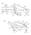
図3は、従来の信号を記録又は再生する装置の側面図である。これは、記録媒体としてカートリッジ(6)に収納されたディスク(60)を用いる。カートリッジ(6)は扁平な矩形状であり、上面にディスク(60)の露出と閉塞を切り換えるシャッタ(61)がスライド自在に取り付けられている。
上面が開口した枠状のキャビネット(2)には、蓋体(4)が枢支(4a)され、キャビネット(2)と蓋体(4)との間には、メカニズムデッキ(5)が装着される。メカニズムデッキ(5)は、ピックアップ(10)を具えたシャーシ(1)上にカートリッジ(6)が挿入されるホルダ(3)を枢支(30)して構成され、ホルダ(3)は蓋体(4)に連結して開閉する。カートリッジ(6)がホルダ(3)に挿入された状態にて、周知の如くシャッタ(61)が開く。蓋体(4)及びホルダ(3)が下降した閉じ状態にてピックアップ(10)がディスク(60)から信号を再生する。
【0003】
図4は、キャビネット(2)と蓋体(4)、及びメカニズムデッキ(5)の斜視図である。メカニズムデッキ(5)のシャーシ(1)は隅部からシャフト(8)を下向きに突出している。キャビネット(2)の下端部からはシャフト(8)に対応した位置に受け板(21)を内向きに突出し、該受け板(21)には嵌め孔(22)が開設されている。嵌め孔(22)には、ダンパ(7)が緊密に嵌まり、ダンパ(7)の中央部にシャフト(8)が挿入される。
図5は、ダンパ(7)とシャフト(8)の正面断面図である。ダンパ(7)はゴム等の弾性材から形成されて、2つのフランジ(70)(70)を互いに離間して設ける。両フランジ(70)(70)間に前記受け板(21)が嵌まる。シャフト(8)は下端部に凹面(80)を形成し、該凹面(80)に下側からネジ(81)が螺合してキャビネット(2)とメカニズムデッキ(5)が締結される。
メカニズムデッキ(5)をキャビネット(2)に装着するには、予めダンパ(7)を受け板(21)に嵌め、次にシャフト(8)をダンパ(7)の上方に配置して、メカニズムデッキ(5)を下降させる。
【0004】
【発明が解決しようとする課題】
メカニズムデッキ(5)は、ダンパ(7)の上から下降して取り付けられるから、キャビネット(2)と蓋体(4)の間には、メカニズムデッキ(5)を下降させる分、即ちシャフト(8)の長さ以上の高さを有する空間が必要になる。即ち、該空間がないと、ホルダ(3)が蓋体(4)に当たり、メカニズムデッキ(5)の取付作業性が悪い。従って、装置全体の厚みが増す。
この場合、蓋体(4)とキャビネット(2)の枢支連結を外して、キャビネット(2)にメカニズムデッキ(5)を取り付け、この後にキャビネット(2)に蓋体(4)を枢支(4a)することも考えられる。しかし、蓋体(4)とキャビネット(2)には、枢支部(4a)が不用意に外れることを防ぐ工夫が成されている。
図6は、該枢支部(4a)の拡大側面図、図7は、図6をA方向から見た断面図である。枢支部(4a)はキャビネット(2)の側板から内向きに突出した枢軸(23)を蓋体(4)の孔(41)に嵌めて構成される。蓋体(4)上にて孔(41)の側方には円弧孔(42)が開設され、該円弧孔(42)には鍔付きピン(24)が内側から嵌まる。鍔付きピン(24)の基端部はキャビネット(2)にかしめ固定されており、蓋体(4)とキャビネット(2)の不用意な外れを防ぐ。
キャビネット(2)にメカニズムデッキ(5)を装着した後に鍔付きピン(24)をかしめ固定して蓋体(4)を取り付けることは、作業性が非常に悪く、事実上不可能である。従って、蓋体(4)とキャビネット(2)を枢支したまま、キャビネット(2)にメカニズムデッキ(5)を装着する必要があるが、前記の如く、装置全体が厚くなり、装置の小型化を求める市場のニーズに対応できない。
本発明は、キャビネット(2)へのメカニズムデッキ(5)の取付作業性を改善し、かつ装置全体の薄型化を達成することを目的とする。
【0005】
【課題を解決する為の手段】
記録又は再生装置は、上記構成に加えて、キャビネット(2)上にて蓋体(4)の自由端部側には、メカニズムデッキ(5)の挿入移行路上に配備されてキャビネット(2)に着脱自在に設けられ、キャビネット(2)から取り外された状態にてメカニズムデッキ(5)の挿入を許す覆い部材(20)が設けられている。蓋体(4)には、メカニズムデッキ(5)が挿入される際に、蓋体(4)とメカニズムデッキ(5)の当接を防ぐ逃げ孔(40)が開設されている。
【0006】
【作用及び効果】
キャビネット(2)から覆い部材(20)を外した状態にて、メカニズムデッキ(5)は蓋体(4)とキャビネット(2)間の空間への挿入が許される。これにより、従来の構成に比して、メカニズムデッキ(5)は該空間への挿入が容易になり、メカニズムデッキ(5)の取付作業性が改善される。また、メカニズムデッキ(5)は該空間への挿入時に、逃げ孔(40)に嵌まるから、蓋体(4)によって挿入を邪魔されることはない。この点でも、メカニズムデッキ(5)の取付作業性が改善される。
【0007】
【発明の実施の形態】
以下、本発明の一例を図を用いて詳述する。キャビネット(2)内にシャーシ(1)が設けられ、蓋体(4)にホルダ(3)が連繋している点、及びキャビネット(2)から突出した受け板(21)にダンパ(7)を取り付けて、該ダンパ(7)にシャーシ(1)から突出したシャフト(8)を嵌める点は、従来と同様であり、詳細な説明を省く。本例にあっては、メカニズムデッキ(5)の取付作業性を改善した点に特徴がある。
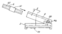
図1は、キャビネット(2)、蓋体(4)、メカニズムデッキ(5)の斜視図である。キャビネット(2)は枠体であり、従来と同様に、蓋体(4)の基端部が枢支(4a)されている。メカニズムデッキ(5)は、蓋体(4)の開き状態にて、蓋体(4)とキャビネット(2)間に挿入されて、キャビネット(2)の受け板(21)に取り付けられる。
キャビネット(2)上にて蓋体(4)の自由端部側には、板状の覆い部材(20)が着脱自在に取り付けられ、該覆い部材(20)はメカニズムデッキ(5)の挿入移行路上に配備されている。覆い部材(20)がキャビネット(2)から取り外された状態にて蓋体(4)とキャビネット(2)間へのメカニズムデッキ(5)の挿入が許される。
蓋体(4)の上面には、逃げ孔(40)が開設され、後記するように該逃げ孔(40)は蓋体(4)とキャビネット(2)間へのメカニズムデッキ(5)の挿入時に、メカニズムデッキ(5)と蓋体(4)の当接を防ぐ。
【0008】
メカニズムデッキの取り付け
図2(a)、(b)は、蓋体(4)とキャビネット(2)間へのメカニズムデッキ(5)の挿入状態を示す側面図である。キャビネット(2)の受け板(21)には、予めダンパ(7)が嵌められている。図2(a)に示すように、メカニズムデッキ(5)は覆い部材(20)が取り外された状態にてキャビネット(2)の前方から蓋体(4)とキャビネット(2)間へ挿入される。図2(b)に示すように、メカニズムデッキ(5)は逃げ孔(40)内に嵌まり、蓋体(4)とは当接しない。即ち、蓋体(4)によってメカニズムデッキ(5)の挿入は邪魔されない。
図2(b)に示す位置から、メカニズムデッキ(5)を下降させて、シャフト(8)をダンパ(7)に嵌める。図5に示すように、ダンパ(7)の下側からシャフト(8)にネジ(81)止めして、メカニズムデッキ(5)とキャビネット(2)が取り付けられる。
【0009】
覆い部材(20)を取り外さなくとも、蓋体(4)とキャビネット(2)間へメカニズムデッキ(5)を挿入することは可能である。しかし、メカニズムデッキ(5)を傾けながら、蓋体(4)とキャビネット(2)間へ挿入する必要がある。また、メカニズムデッキ(5)を下降させて、キャビネット(2)に取り付ける際に、作業性が悪い。特に蓋体(4)とキャビネット(2)の枢支部(4a)の近傍では、蓋体(4)とキャビネット(2)間の空間の高さが低く、該近傍に位置する受け板(図8(a)のA部)にシャーシ(1)を取り付ける際の作業性が悪い。従って、覆い部材(20)を取り外し、且つホルダ(3)に逃げ孔(40)を開設することにより、メカニズムデッキ(5)を取り付ける際の作業性が良くなる。
【0010】
上記実施例の説明は、本発明を説明するためのものであって、特許請求の範囲に記載の発明を限定し、或は範囲を減縮する様に解すべきではない。又、本発明の各部構成は上記実施例に限らず、特許請求の範囲に記載の技術的範囲内で種々の変形が可能であることは勿論である。
【図面の簡単な説明】
【図1】キャビネット、蓋体、メカニズムデッキの斜視図である。
【図2】(a)、(b)は、蓋体とキャビネット間へのメカニズムデッキの挿入状態を示す側面図である。
【図3】従来の信号を記録又は再生する装置の側面図である。
【図4】従来のキャビネットと蓋体、及びメカニズムデッキの斜視図である。
【図5】ダンパとシャフトの正面断面図である。
【図6】蓋体とキャビネットの枢支部の拡大側面図である。
【図7】図6をA方向から見た断面図である。
【符号の説明】
(1) シャーシ
(2) キャビネット
(3) ホルダ
(4) 蓋体
(5) メカニズムデッキ
(7) ダンパ
(20) 覆い部材
(40) 逃げ孔[0001]
BACKGROUND OF THE INVENTION
The present invention relates to a signal recording or reproducing apparatus for a disk stored in a cartridge.
[0002]
[Prior art]
FIG. 3 is a side view of a conventional apparatus for recording or reproducing a signal. This uses a disk (60) housed in a cartridge (6) as a recording medium. The cartridge (6) has a flat rectangular shape, and a shutter (61) for switching between exposure and closing of the disk (60) is slidably mounted on the upper surface.
A lid (4) is pivotally supported (4a) in a frame-shaped cabinet (2) with an open upper surface, and a mechanism deck (5) is mounted between the cabinet (2) and the lid (4). Is done. The mechanism deck (5) is configured by pivotally supporting (30) a holder (3) into which a cartridge (6) is inserted on a chassis (1) having a pickup (10), and the holder (3) is a lid. Open and close connected to (4). In a state where the cartridge (6) is inserted into the holder (3), the shutter (61) is opened as is well known. The pickup (10) reproduces a signal from the disc (60) in the closed state in which the lid (4) and the holder (3) are lowered.
[0003]
FIG. 4 is a perspective view of the cabinet (2), the lid (4), and the mechanism deck (5). The chassis (1) of the mechanism deck (5) projects the shaft (8) downward from the corner. A receiving plate (21) protrudes inward from the lower end of the cabinet (2) at a position corresponding to the shaft (8), and a fitting hole (22) is formed in the receiving plate (21). The damper (7) is closely fitted in the fitting hole (22), and the shaft (8) is inserted into the center of the damper (7).
FIG. 5 is a front sectional view of the damper (7) and the shaft (8). The damper (7) is made of an elastic material such as rubber, and has two flanges (70) and (70) spaced apart from each other. The receiving plate (21) is fitted between the flanges (70) (70). The shaft (8) has a concave surface (80) at the lower end, and a screw (81) is screwed into the concave surface (80) from below to fasten the cabinet (2) and the mechanism deck (5).
To mount the mechanism deck (5) to the cabinet (2), place the damper (7) in the receiving plate (21) in advance, and then place the shaft (8) above the damper (7). Lower (5).
[0004]
[Problems to be solved by the invention]
Since the mechanism deck (5) is mounted by being lowered from the top of the damper (7), the mechanism deck (5) is lowered between the cabinet (2) and the lid (4), that is, the shaft (8). A space having a height equal to or greater than the length of) is required. That is, if there is no such space, the holder (3) hits the lid (4), and the workability of attaching the mechanism deck (5) is poor. Therefore, the thickness of the entire apparatus increases.
In this case, the pivotal connection between the lid (4) and the cabinet (2) is removed, the mechanism deck (5) is attached to the cabinet (2), and then the lid (4) is pivotally supported on the cabinet (2) ( 4a) is also conceivable. However, the lid (4) and the cabinet (2) are devised to prevent the pivot (4a) from being inadvertently detached.
FIG. 6 is an enlarged side view of the pivot portion (4a), and FIG. 7 is a cross-sectional view of FIG. The pivot (4a) is configured by fitting a pivot (23) projecting inward from the side plate of the cabinet (2) into the hole (41) of the lid (4). An arc hole (42) is formed on the side of the hole (41) on the lid (4), and a hooked pin (24) is fitted into the arc hole (42) from the inside. The base end of the hooked pin (24) is fixed by caulking to the cabinet (2) to prevent inadvertent detachment of the lid (4) and cabinet (2).
After the mechanism deck (5) is mounted on the cabinet (2), it is impossible to attach the lid (4) by caulking and fixing the hooked pin (24), which is practically impossible. Therefore, it is necessary to mount the mechanism deck (5) on the cabinet (2) while pivotally supporting the lid (4) and the cabinet (2). However, as described above, the entire device becomes thicker and the device is downsized. Cannot meet the needs of the market.
An object of the present invention is to improve the workability of attaching the mechanism deck (5) to the cabinet (2) and to achieve a reduction in the thickness of the entire apparatus.
[0005]
[Means for solving the problems]
In addition to the above-mentioned configuration, the recording or reproducing device is disposed on the free end portion of the lid (4) on the cabinet (2) on the insertion transition path of the mechanism deck (5) to the cabinet (2). A cover member (20) that is detachably provided and allows the mechanism deck (5) to be inserted in a state of being detached from the cabinet (2) is provided. The lid (4) is provided with an escape hole (40) for preventing the lid (4) and the mechanism deck (5) from coming into contact when the mechanism deck (5) is inserted.
[0006]
[Action and effect]
The mechanism deck (5) is allowed to be inserted into the space between the lid (4) and the cabinet (2) with the covering member (20) removed from the cabinet (2). Thereby, compared with the conventional structure, the mechanism deck (5) can be easily inserted into the space, and the mounting workability of the mechanism deck (5) is improved. Moreover, since the mechanism deck (5) fits into the escape hole (40) when inserted into the space, the insertion is not obstructed by the lid (4). This also improves the workability of mounting the mechanism deck (5).
[0007]
DETAILED DESCRIPTION OF THE INVENTION
Hereinafter, an example of the present invention will be described in detail with reference to the drawings. The chassis (1) is provided in the cabinet (2), the holder (3) is connected to the lid (4), and the damper (7) is attached to the receiving plate (21) protruding from the cabinet (2). The point of attaching and fitting the shaft (8) protruding from the chassis (1) to the damper (7) is the same as in the prior art, and a detailed description is omitted. This example is characterized in that the mounting workability of the mechanism deck (5) is improved.
FIG. 1 is a perspective view of a cabinet (2), a lid (4), and a mechanism deck (5). The cabinet (2) is a frame, and the base end of the lid (4) is pivotally supported (4a) as in the prior art. The mechanism deck (5) is inserted between the lid (4) and the cabinet (2) in the opened state of the lid (4) and attached to the receiving plate (21) of the cabinet (2).
A plate-like cover member (20) is detachably attached to the free end of the lid (4) on the cabinet (2), and the cover member (20) is inserted into the mechanism deck (5). It is deployed on the street. The mechanism deck (5) can be inserted between the lid (4) and the cabinet (2) with the cover member (20) removed from the cabinet (2).
An escape hole (40) is opened on the upper surface of the lid (4). As will be described later, the escape hole (40) is inserted into the mechanism deck (5) between the lid (4) and the cabinet (2). Occasionally, contact between the mechanism deck (5) and the lid (4) is prevented.
[0008]
Mounting of mechanism deck Figs. 2 (a) and 2 (b) are side views showing a state in which the mechanism deck (5) is inserted between the lid (4) and the cabinet (2). A damper (7) is fitted in advance on the receiving plate (21) of the cabinet (2). As shown in FIG. 2 (a), the mechanism deck (5) is inserted between the lid (4) and the cabinet (2) from the front of the cabinet (2) with the covering member (20) removed. . As shown in FIG. 2 (b), the mechanism deck (5) fits into the escape hole (40) and does not contact the lid (4). That is, the insertion of the mechanism deck (5) is not disturbed by the lid (4).
The mechanism deck (5) is lowered from the position shown in FIG. 2 (b), and the shaft (8) is fitted into the damper (7). As shown in FIG. 5, the mechanism deck (5) and the cabinet (2) are attached by fixing screws (81) to the shaft (8) from the lower side of the damper (7).
[0009]
It is possible to insert the mechanism deck (5) between the lid (4) and the cabinet (2) without removing the covering member (20). However, it is necessary to insert the mechanism deck (5) between the lid (4) and the cabinet (2) while tilting the mechanism deck (5). Further, when the mechanism deck (5) is lowered and attached to the cabinet (2), workability is poor. Especially in the vicinity of the pivot (4a) of the lid (4) and the cabinet (2), the height of the space between the lid (4) and the cabinet (2) is low, and a receiving plate (Fig. 8) The workability when attaching the chassis (1) to part A of (a) is poor. Accordingly, by removing the covering member (20) and opening the escape hole (40) in the holder (3), the workability when attaching the mechanism deck (5) is improved.
[0010]
The above description of the embodiments is for explaining the present invention, and should not be construed as limiting the invention described in the claims or reducing the scope thereof. In addition, the configuration of each part of the present invention is not limited to the above embodiment, and various modifications can be made within the technical scope described in the claims.
[Brief description of the drawings]
FIG. 1 is a perspective view of a cabinet, a lid, and a mechanism deck.
FIGS. 2A and 2B are side views showing an insertion state of a mechanism deck between a lid and a cabinet.
FIG. 3 is a side view of a conventional apparatus for recording or reproducing a signal.
FIG. 4 is a perspective view of a conventional cabinet, lid, and mechanism deck.
FIG. 5 is a front sectional view of a damper and a shaft.
FIG. 6 is an enlarged side view of the lid and the pivotal support of the cabinet.
7 is a cross-sectional view of FIG. 6 viewed from the direction A. FIG.
[Explanation of symbols]
(1) Chassis
(2) Cabinet
(3) Holder
(4) Lid
(5) Mechanism deck
(7) Damper
(20) Cover member
(40) Escape hole
Claims (2)
キャビネット(2)上にて蓋体(4)の自由端部側には、メカニズムデッキ(5)の挿入移行路上に配備されてキャビネット(2)に着脱自在に設けられ、キャビネット(2)から取り外された状態にてメカニズムデッキ(5)の挿入を許す覆い部材(20)が設けられ、
蓋体(4)には、メカニズムデッキ(5)が挿入される際に、蓋体(4)とメカニズムデッキ(5)の当接を防ぐ逃げ孔(40)が開設されたことを特徴とする記録又は再生装置。The base end of the lid (4) is rotatably provided on the frame-shaped cabinet (2), and the mechanism deck (5) is mounted on the cabinet (2) via a damper (7). In the open state of the body (4), a space is formed between the lid (4) and the cabinet (2) in which the mechanism deck (5) is inserted from the free end side of the lid (4). In a recording or playback device,
On the cabinet (2), on the free end side of the lid (4), the mechanism deck (5) is installed on the insertion transition path and is detachably attached to the cabinet (2), and is removed from the cabinet (2). A cover member (20) that allows the mechanism deck (5) to be inserted in the
The lid (4) is provided with a relief hole (40) for preventing the lid (4) and the mechanism deck (5) from contacting when the mechanism deck (5) is inserted. Recording or playback device.
Priority Applications (1)
| Application Number | Priority Date | Filing Date | Title |
|---|---|---|---|
| JP28259599A JP3676144B2 (en) | 1999-10-04 | 1999-10-04 | Signal recording or playback device |
Applications Claiming Priority (1)
| Application Number | Priority Date | Filing Date | Title |
|---|---|---|---|
| JP28259599A JP3676144B2 (en) | 1999-10-04 | 1999-10-04 | Signal recording or playback device |
Publications (2)
| Publication Number | Publication Date |
|---|---|
| JP2001101750A JP2001101750A (en) | 2001-04-13 |
| JP3676144B2 true JP3676144B2 (en) | 2005-07-27 |
Family
ID=17654559
Family Applications (1)
| Application Number | Title | Priority Date | Filing Date |
|---|---|---|---|
| JP28259599A Expired - Fee Related JP3676144B2 (en) | 1999-10-04 | 1999-10-04 | Signal recording or playback device |
Country Status (1)
| Country | Link |
|---|---|
| JP (1) | JP3676144B2 (en) |
-
1999
- 1999-10-04 JP JP28259599A patent/JP3676144B2/en not_active Expired - Fee Related
Also Published As
| Publication number | Publication date |
|---|---|
| JP2001101750A (en) | 2001-04-13 |
Similar Documents
| Publication | Publication Date | Title |
|---|---|---|
| US4424606A (en) | Hinge for opening and closing a dust cover | |
| JP2006173846A (en) | Stand for liquid crystal television and stand for display device | |
| JP3676144B2 (en) | Signal recording or playback device | |
| CN100426414C (en) | Data recording/reproducing apparatus | |
| JP3332043B2 (en) | Disk Cartridge | |
| JPH10255369A (en) | Disk recording and reproducing device | |
| JP2001338485A (en) | Mounting structure for holder | |
| JP2951328B1 (en) | Recording / reproducing apparatus for disc stored in cartridge | |
| KR0149123B1 (en) | A device that attaches or detaches a minidisc player from a double deck | |
| JP3765704B2 (en) | Recording medium insertion slot structure of recording medium recording / reproducing apparatus | |
| KR100633879B1 (en) | Cassette door mounting structure of cassette player | |
| JP2500835B2 (en) | Disc playback device | |
| EP1622439A2 (en) | Door opening and closing device and electronic apparatus having the same | |
| JP2002133842A (en) | Panel device of disk player, and disk player integrated television apparatus | |
| JP2966812B2 (en) | Disk recording and playback device | |
| JP2002216465A (en) | Device having pivotally supported lid body | |
| JP3644040B2 (en) | Portable electronic devices | |
| JP2001332875A (en) | Fixing structure of cover | |
| KR100440978B1 (en) | Opening and closing apparatus for portable DVD player | |
| KR830000029Y1 (en) | Casatte hinge | |
| JP2006221266A (en) | Opening and closing door mechanism for recording media | |
| JP3615442B2 (en) | Electrical equipment that pivotally supports the lid | |
| JP2558314Y2 (en) | Equipment anti-vibration mechanism | |
| KR200305480Y1 (en) | Open and shut-doorappatatus of cd-player | |
| KR20030002569A (en) | Coupling structure for portable compact disc player and outside electronic machine |
Legal Events
| Date | Code | Title | Description |
|---|---|---|---|
| A977 | Report on retrieval |
Free format text: JAPANESE INTERMEDIATE CODE: A971007 Effective date: 20050221 |
|
| TRDD | Decision of grant or rejection written | ||
| A01 | Written decision to grant a patent or to grant a registration (utility model) |
Free format text: JAPANESE INTERMEDIATE CODE: A01 Effective date: 20050419 |
|
| A61 | First payment of annual fees (during grant procedure) |
Free format text: JAPANESE INTERMEDIATE CODE: A61 Effective date: 20050427 |
|
| FPAY | Renewal fee payment (event date is renewal date of database) |
Free format text: PAYMENT UNTIL: 20080513 Year of fee payment: 3 |
|
| FPAY | Renewal fee payment (event date is renewal date of database) |
Free format text: PAYMENT UNTIL: 20090513 Year of fee payment: 4 |
|
| LAPS | Cancellation because of no payment of annual fees |