JP3675725B2 - Heat exchanger - Google Patents
Heat exchanger Download PDFInfo
- Publication number
- JP3675725B2 JP3675725B2 JP2001060089A JP2001060089A JP3675725B2 JP 3675725 B2 JP3675725 B2 JP 3675725B2 JP 2001060089 A JP2001060089 A JP 2001060089A JP 2001060089 A JP2001060089 A JP 2001060089A JP 3675725 B2 JP3675725 B2 JP 3675725B2
- Authority
- JP
- Japan
- Prior art keywords
- passage
- header
- heat exchanger
- supply system
- heat exchange
- Prior art date
- Legal status (The legal status is an assumption and is not a legal conclusion. Google has not performed a legal analysis and makes no representation as to the accuracy of the status listed.)
- Expired - Fee Related
Links
Images


Classifications
-
- F—MECHANICAL ENGINEERING; LIGHTING; HEATING; WEAPONS; BLASTING
- F28—HEAT EXCHANGE IN GENERAL
- F28F—DETAILS OF HEAT-EXCHANGE AND HEAT-TRANSFER APPARATUS, OF GENERAL APPLICATION
- F28F9/00—Casings; Header boxes; Auxiliary supports for elements; Auxiliary members within casings
- F28F9/02—Header boxes; End plates
- F28F9/026—Header boxes; End plates with static flow control means, e.g. with means for uniformly distributing heat exchange media into conduits
- F28F9/0278—Header boxes; End plates with static flow control means, e.g. with means for uniformly distributing heat exchange media into conduits in the form of stacked distribution plates or perforated plates arranged over end plates
-
- C—CHEMISTRY; METALLURGY
- C01—INORGANIC CHEMISTRY
- C01B—NON-METALLIC ELEMENTS; COMPOUNDS THEREOF; METALLOIDS OR COMPOUNDS THEREOF NOT COVERED BY SUBCLASS C01C
- C01B3/00—Hydrogen; Gaseous mixtures containing hydrogen; Separation of hydrogen from mixtures containing it; Purification of hydrogen
- C01B3/02—Production of hydrogen or of gaseous mixtures containing a substantial proportion of hydrogen
- C01B3/32—Production of hydrogen or of gaseous mixtures containing a substantial proportion of hydrogen by reaction of gaseous or liquid organic compounds with gasifying agents, e.g. water, carbon dioxide, air
-
- F—MECHANICAL ENGINEERING; LIGHTING; HEATING; WEAPONS; BLASTING
- F28—HEAT EXCHANGE IN GENERAL
- F28D—HEAT-EXCHANGE APPARATUS, NOT PROVIDED FOR IN ANOTHER SUBCLASS, IN WHICH THE HEAT-EXCHANGE MEDIA DO NOT COME INTO DIRECT CONTACT
- F28D9/00—Heat-exchange apparatus having stationary plate-like or laminated conduit assemblies for both heat-exchange media, the media being in contact with different sides of a conduit wall
- F28D9/0062—Heat-exchange apparatus having stationary plate-like or laminated conduit assemblies for both heat-exchange media, the media being in contact with different sides of a conduit wall the conduits for one heat-exchange medium being formed by spaced plates with inserted elements
-
- F—MECHANICAL ENGINEERING; LIGHTING; HEATING; WEAPONS; BLASTING
- F28—HEAT EXCHANGE IN GENERAL
- F28D—HEAT-EXCHANGE APPARATUS, NOT PROVIDED FOR IN ANOTHER SUBCLASS, IN WHICH THE HEAT-EXCHANGE MEDIA DO NOT COME INTO DIRECT CONTACT
- F28D9/00—Heat-exchange apparatus having stationary plate-like or laminated conduit assemblies for both heat-exchange media, the media being in contact with different sides of a conduit wall
- F28D9/0093—Multi-circuit heat-exchangers, e.g. integrating different heat exchange sections in the same unit or heat-exchangers for more than two fluids
-
- H—ELECTRICITY
- H01—ELECTRIC ELEMENTS
- H01M—PROCESSES OR MEANS, e.g. BATTERIES, FOR THE DIRECT CONVERSION OF CHEMICAL ENERGY INTO ELECTRICAL ENERGY
- H01M8/00—Fuel cells; Manufacture thereof
- H01M8/06—Combination of fuel cells with means for production of reactants or for treatment of residues
- H01M8/0606—Combination of fuel cells with means for production of reactants or for treatment of residues with means for production of gaseous reactants
- H01M8/0612—Combination of fuel cells with means for production of reactants or for treatment of residues with means for production of gaseous reactants from carbon-containing material
-
- C—CHEMISTRY; METALLURGY
- C01—INORGANIC CHEMISTRY
- C01B—NON-METALLIC ELEMENTS; COMPOUNDS THEREOF; METALLOIDS OR COMPOUNDS THEREOF NOT COVERED BY SUBCLASS C01C
- C01B2203/00—Integrated processes for the production of hydrogen or synthesis gas
- C01B2203/12—Feeding the process for making hydrogen or synthesis gas
- C01B2203/1288—Evaporation of one or more of the different feed components
-
- F—MECHANICAL ENGINEERING; LIGHTING; HEATING; WEAPONS; BLASTING
- F28—HEAT EXCHANGE IN GENERAL
- F28D—HEAT-EXCHANGE APPARATUS, NOT PROVIDED FOR IN ANOTHER SUBCLASS, IN WHICH THE HEAT-EXCHANGE MEDIA DO NOT COME INTO DIRECT CONTACT
- F28D21/00—Heat-exchange apparatus not covered by any of the groups F28D1/00 - F28D20/00
- F28D2021/0019—Other heat exchangers for particular applications; Heat exchange systems not otherwise provided for
- F28D2021/0043—Other heat exchangers for particular applications; Heat exchange systems not otherwise provided for for fuel cells
-
- F—MECHANICAL ENGINEERING; LIGHTING; HEATING; WEAPONS; BLASTING
- F28—HEAT EXCHANGE IN GENERAL
- F28D—HEAT-EXCHANGE APPARATUS, NOT PROVIDED FOR IN ANOTHER SUBCLASS, IN WHICH THE HEAT-EXCHANGE MEDIA DO NOT COME INTO DIRECT CONTACT
- F28D21/00—Heat-exchange apparatus not covered by any of the groups F28D1/00 - F28D20/00
- F28D2021/0019—Other heat exchangers for particular applications; Heat exchange systems not otherwise provided for
- F28D2021/0061—Other heat exchangers for particular applications; Heat exchange systems not otherwise provided for for phase-change applications
- F28D2021/0064—Vaporizers, e.g. evaporators
-
- H—ELECTRICITY
- H01—ELECTRIC ELEMENTS
- H01M—PROCESSES OR MEANS, e.g. BATTERIES, FOR THE DIRECT CONVERSION OF CHEMICAL ENERGY INTO ELECTRICAL ENERGY
- H01M2250/00—Fuel cells for particular applications; Specific features of fuel cell system
- H01M2250/20—Fuel cells in motive systems, e.g. vehicle, ship, plane
-
- H—ELECTRICITY
- H01—ELECTRIC ELEMENTS
- H01M—PROCESSES OR MEANS, e.g. BATTERIES, FOR THE DIRECT CONVERSION OF CHEMICAL ENERGY INTO ELECTRICAL ENERGY
- H01M8/00—Fuel cells; Manufacture thereof
- H01M8/06—Combination of fuel cells with means for production of reactants or for treatment of residues
- H01M8/0606—Combination of fuel cells with means for production of reactants or for treatment of residues with means for production of gaseous reactants
- H01M8/0612—Combination of fuel cells with means for production of reactants or for treatment of residues with means for production of gaseous reactants from carbon-containing material
- H01M8/0625—Combination of fuel cells with means for production of reactants or for treatment of residues with means for production of gaseous reactants from carbon-containing material in a modular combined reactor/fuel cell structure
- H01M8/0631—Reactor construction specially adapted for combination reactor/fuel cell
-
- Y—GENERAL TAGGING OF NEW TECHNOLOGICAL DEVELOPMENTS; GENERAL TAGGING OF CROSS-SECTIONAL TECHNOLOGIES SPANNING OVER SEVERAL SECTIONS OF THE IPC; TECHNICAL SUBJECTS COVERED BY FORMER USPC CROSS-REFERENCE ART COLLECTIONS [XRACs] AND DIGESTS
- Y02—TECHNOLOGIES OR APPLICATIONS FOR MITIGATION OR ADAPTATION AGAINST CLIMATE CHANGE
- Y02E—REDUCTION OF GREENHOUSE GAS [GHG] EMISSIONS, RELATED TO ENERGY GENERATION, TRANSMISSION OR DISTRIBUTION
- Y02E60/00—Enabling technologies; Technologies with a potential or indirect contribution to GHG emissions mitigation
- Y02E60/30—Hydrogen technology
- Y02E60/50—Fuel cells
-
- Y—GENERAL TAGGING OF NEW TECHNOLOGICAL DEVELOPMENTS; GENERAL TAGGING OF CROSS-SECTIONAL TECHNOLOGIES SPANNING OVER SEVERAL SECTIONS OF THE IPC; TECHNICAL SUBJECTS COVERED BY FORMER USPC CROSS-REFERENCE ART COLLECTIONS [XRACs] AND DIGESTS
- Y02—TECHNOLOGIES OR APPLICATIONS FOR MITIGATION OR ADAPTATION AGAINST CLIMATE CHANGE
- Y02T—CLIMATE CHANGE MITIGATION TECHNOLOGIES RELATED TO TRANSPORTATION
- Y02T90/00—Enabling technologies or technologies with a potential or indirect contribution to GHG emissions mitigation
- Y02T90/40—Application of hydrogen technology to transportation, e.g. using fuel cells
Description
【0001】
【発明の属する技術分野】
本発明は、燃料電池システムの蒸発器などに適用可能な熱交換器の改良に関する。
【0002】
【従来の技術と解決すべき課題】
燃料電池には、燃料電池スタックに供給する水素ガスを生成するために、アルコールと水とを蒸発器により気化して改質器に供給する改質燃料型のシステムがある。このようにアルコールと水とを気化するにあたり、それぞれを別個の蒸発器にて蒸発させる構成とすると蒸発器が2台必要になることからコストが増したり、特に燃料電池自動車のような移動体システムにおいては配管スペースなどレイアウトの面で問題が生じる。これに対して、例えば特開平9-79694号公報に開示されたもののように、蒸発器の入口部でアルコールと水とを別々に噴射供給し、これらを混合したうえで熱交換部に供給するようにしたものがある。しかしながら、このように予め混合した燃料を熱交換部に供給する構成によると、アルコールと水との比率を変化させたときに、それ以前に熱交換部に残留していた分が蒸発を終えるまでは比率が変化しないため応答性が悪いという問題がある。
【0003】
本発明はこのような問題点に着目してなされたもので、アルコールと水など多種類の流体を熱交換する熱交換器であって、スペース効率がよく、低コストで応答性のよい熱交換器を提供することを目的としている。
【0004】
【課題を解決するための手段】
第1の発明は、流体が通過する通路部を多数形成した熱交換部に前記通路部に液状流体を分散供給するヘッダ部を設けた熱交換器において、前記ヘッダ部および通路部を、共通の熱交換部内にて互いに独立して流体を流通させる複数の系統から構成し、前記ヘッダ部を、該ヘッダ部の側面に設けた入口部から流入する液状流体を前記通路部に通過させる開口部を多数設けた下プレートと、この下プレートとの間に分散空間部を形成する上プレートとで形成し、前記分散空間部には、前記入口部から流入する液状流体の流れを横断する方向に分配空間を形成し、この分配空間から前記入口部に対向して延びる複数の流体通路を形成する通路壁部を設けた。
【0005】
第2の発明は、前記第1の発明のヘッダ部および通路部を、水供給系統とアルコール供給系統の2系統から構成した。
【0006】
第3の発明は、前記第2の発明の水供給系統の通路部を、アルコール供給系統の通路部に比較して受熱量が大となるように通路形状を設定したものとした。
【0007】
第4の発明は、前記第2の発明において、その水供給系統の通路部は熱交換部の比較的高温域に、アルコール供給系統の通路部は熱交換部の比較的低温域にそれぞれ設けた。
【0009】
第5の発明は、前記第1の発明のヘッダ部を、共通する熱交換部の上に複数個を設けた。
【0010】
第6の発明は、前記第1の発明のヘッダ部を、複数の入口部と、該入口部に対応して画成した複数の分散空間部とから構成した。
【0011】
【作用・効果】
熱交換器のヘッダ部と通路部とを共通の熱交換部にて互いに独立して流体を通過させる複数の系統から構成したので、異なる種類の流体を熱交換させる熱交換器として小型化と低コスト化を図ることができる。また、異なる種類の流体を別個に熱交換させる構成であるので、それぞれの比率に影響を受けることなく速やかに熱交換を行わせることができる。
【0012】
特に本発明によれば、ヘッダ部の入口部から分散空間部に流入した液状流体は通路壁部により分岐状に画成された流体通路に分流して各流体通路に面した開口部から下方の熱交換部の通路部へと流入する。このとき、流体は分散空間部内を通路壁部により画成された限られた容積の通路部を経由して熱交換部へと流れ込む。ヘッダ部内の流体が通過する部分の容積は通路壁部により必要最小限となっているため、ヘッダ部に供給された液状流体は速やかに熱交換部へと到達する。これにより、本発明による熱交換器を燃料電池の蒸発器として適用した場合には、水またはアルコール等の供給から蒸発燃料が得られるまでの応答時間をより短縮することができる。また、改質器停止時においても、ヘッダ部内に留まっている燃料や水の量を抑えることができるので、燃料供給停止から改質器停止までの時間を短くすることができる。この発明において、ヘッダ部は第5の発明として示したように、共通する熱交換部の上に複数個を設けた構成、または第6の発明として示したようにヘッダ部を複数の入口部と、該入口部に対応して画成した複数の分散空間部とから構成することができる。
【0013】
また、例えば第2の発明として示したようにヘッダ部と通路部とを、水供給系統とアルコール供給系統の2系統から構成した場合、水とアルコールの混合比率がそれぞれの系統に速やかに反映されるので、本発明を応答性のよい蒸発器として適用することができる。この場合、第3の発明のように水供給系統の通路部をアルコール供給系統の通路部に比較して受熱量が大となるように通路形状(通路断面形状、受熱フィン形状、受熱フィン表面積など)を設定し、あるいは第4の発明のように水供給系統の通路部は熱交換部の比較的高温域に、アルコール供給系統の通路部は熱交換部の比較的低温域にそれぞれ設けた構成とすることにより、比較的沸点の高い水を高温域にて効率よく蒸発させることができる。
【0014】
【発明の実施の形態】
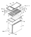
以下、本発明を燃料電池システムの蒸発器として構成した実施形態につき図面に基づいて説明する。図1または図2において、1は蒸発器の第1のヘッダ部であり、上プレート1a、下プレート1b、櫛型部材2、燃料供給部材3からなる。また、7は第2のヘッダ部であり、上プレート7a、下プレート7b、櫛形部材8、燃料供給部材9からなる。6はその上面に前記ヘッダ部1と7が取り付けられる熱交換部である。
【0015】
熱交換部6は、水またはアルコール(メタノール)を下方に通過させる通路部6aを多数開口させた低温流体用層状部6bと、前記水またはアルコールを加熱するための高温ガスを側方から通過させる高温流体用層状部6cとを積層して構成されている。この熱交換部6の上面に、前記高温ガス流の下流側で比較的低温となる領域に第1のヘッダ部1が、上流側で比較的高温となる領域に第2のヘッダ部7が、それぞれ取り付けられる。
【0016】
第1のヘッダ部1を構成する上プレート1aと下プレート1bは上下方向に結合され、その一辺に燃料供給部材3が取り付けられる。また、同様にして第2のヘッダ部7を構成する上プレート7aと下プレート7bは上下方向に結合され、その一辺に燃料供給部材9が取り付けられる。これらは溶接またはろう付けにより結合され、それぞれ内部に薄い偏平状の分散空間部Saを画成する。燃料供給部材3に設けられた燃料入口部3aはヘッダ部1の分散空間部Saに臨んで開口し、図示しないアルコール供給系統から圧送されてくるアルコールをヘッダ部1内に導入する。また、燃料供給部材9に設けられた燃料入口部9aはヘッダ部9の分散空間部Saに臨んで開口し、図示しない水供給系統から圧送されてくる水をヘッダ部9内に導入する。
【0017】
ヘッダ部1の櫛形部材2は、前記入口部3aに対向して位置する辺部2aから該入口部3aに向かって延びる腕部2bを該辺部2aに沿って多数配設した形状をしており、上プレート1aと下プレート1bとの間の挟持される態様で分散空間部Saに収装されている。櫛形部材2は、図2にも示したようにヘッダ部1内の分散空間部Sa内を前記腕部2bにより画成して複数の分岐した流体通路5を形成している。また、櫛形部材2と燃料供給部材3の間には、アルコール燃料を流体通路5に均一に分配するための分配空間Sbが設けられている。ヘッダ部1のデッドボリュームを最小限とするために、分散空間部Saまたは櫛形部材2の厚みはたとえば1mm程度に小さく抑えられ、また腕部2bの幅はできるだけ大きくして燃料通路5の幅も最小限とされている。第2のヘッダ部7についても、櫛形部材8により前記と同様にその分配通路部Sa内にて最小の容積で効率よく水を分散させるように構成されている。
【0018】
各ヘッダ部1,7の下プレート1b、7bには、前記分岐状の各流体通路5に臨むように多数の小穴状の開口部4が形成されている。これらの開口部4の通路部横断方向の開口間隔(ピッチ)は、ヘッダ部1または7を取り付けた状態で、前述した熱交換部6の通路部6aに連通するように、通路部6a相互の間隔と同一に設定されている。
【0019】
前記構成において、第1のヘッダ部1の燃料入口部3aから噴射供給されたアルコールは分配空間Sb、分散空間部Saないしは流体通路5内を満たしたのち、下プレート1bに設けられた開口部4により熱交換部6の通路部6aへと均等に供給される。このとき、櫛形部材2によって分散空間部Sa内の余剰容積が削減されているので燃料供給開始から熱交換部流入までの時間が大幅に短縮される。第2のヘッダ部7に噴射供給された水についても前記と同様にして速やかに熱交換部6の通路部6aに供給される。このとき、沸点の低いアルコールは熱交換部6の比較的低温の領域にて、沸点の高い水は比較的高温の領域にて、それぞれの通路部6aへと個別に流れ込むので、それぞれの比率に係わらず効率よく燃料蒸気を発生させることができる。発生した燃料蒸気は図示しない出口部から改質器へと向けて供給される。
【0020】
図3に本発明の第2の実施形態を示す。これは基本的な構成は前記第1の実施形態と同一であるが、ただしこの実施形態ではヘッダ部1を単一構成とし、その内部の分散空間部Saを水用とアルコール用の2系統に画成している。すなわち、図示したように燃料供給部3には中央の水用の入口部10とその両側の2個のアルコール用の入口部11が設けられると共に、これらに対応するように燃料分散部Saが中央の水用の分散部Sa1とその両側のアルコール用の分散部Sa2とに画成されている。前記分散部Sa1とSa2とは、櫛形部材2の中間部分の2個の腕部2bを燃料供給部材3に向けて延長して分配空間Sbを横断方向に3分割することにより画成されている。
【0021】
この実施形態においても、水とアルコールとはそれぞれの入口部10、11から流入したのち、個々の分散空間部Sa1、Sa2および通路部6aを経て高温ガスとの熱交換を行う。また、水は熱交換部6の比較的高温となる中央域にて熱交換が行われる。したがって第1の実施形態と同様に効率よく燃料蒸気を発生させることができる。また、この実施形態はヘッダ部1が単一構成であるので、構造が簡略でありより低コストなものとすることができる。
【0022】
なお、前記各実施形態は流体として水またはアルコールを熱交換器の上方から供給するようにした例を示したものであるが、これに限られず下方の一方向から燃料供給を行うようにした構成においても本発明は有効である。また、ヘッダ部の構成についても実施形態の構成に限られるものではなく、例えば上プレートまたは下プレートにビードプレス加工により波形形状を与え、この波形形状により複数の流体通路を画成する構成とすることもでき、これによればより低コスト化を図れるとともにヘッダ部ないしは熱交換器の剛性を高めることもできる。
【図面の簡単な説明】
【図1】本発明による蒸発器の第1の実施形態の組み立て図。
【図2】第1の実施形態のヘッダ部の縦断面図。
【図3】本発明による蒸発器の第2の実施形態の組み立て図。
【符号の説明】
1、7 蒸発器のヘッダ部
1a、7a 上プレート
1b、7b 下プレート
2、8 櫛形部材
2a 辺部
2b 腕部
3、9 燃料供給部材
3a,9a 燃料入口部
4 開口部
5 流体通路
6 熱交換部
6a 通路部
6b 低温流体用層状部
6c 高温流体用層状部
Sa 分散空間部
Sb 分配空間[0001]
BACKGROUND OF THE INVENTION
The present invention relates to an improvement of a heat exchanger applicable to an evaporator of a fuel cell system.
[0002]
[Prior art and problems to be solved]
Fuel cells include a reformed fuel type system in which alcohol and water are vaporized by an evaporator and supplied to the reformer in order to generate hydrogen gas to be supplied to the fuel cell stack. In this way, when vaporizing alcohol and water, if each is configured to evaporate with separate evaporators, two evaporators are required, which increases costs, and in particular mobile system such as a fuel cell vehicle However, there is a problem in layout such as piping space. On the other hand, for example, as disclosed in Japanese Patent Application Laid-Open No. 9-79694, alcohol and water are separately supplied at the inlet of the evaporator, mixed, and then supplied to the heat exchange unit. There is something like that. However, according to the configuration in which the premixed fuel is supplied to the heat exchanging portion in this way, when the ratio of alcohol and water is changed, the amount remaining in the heat exchanging portion before the evaporation is finished. Has the problem of poor response because the ratio does not change.
[0003]
The present invention has been made paying attention to such problems, and is a heat exchanger for exchanging various types of fluids such as alcohol and water, and is a space-efficient, low-cost and responsive heat exchanger. The purpose is to provide a vessel.
[0004]
[Means for Solving the Problems]
A first aspect of the present invention is a heat exchanger in which a header portion that supplies a liquid fluid to the passage portion is provided in a heat exchange portion in which a large number of passage portions through which a fluid passes is provided. An opening that is configured from a plurality of systems that allow fluids to flow independently from each other in the heat exchanging portion, and that allows the liquid fluid flowing in from the inlet portion provided on the side surface of the header portion to pass through the passage portion. A plurality of lower plates and an upper plate forming a dispersion space between the lower plates are formed. The dispersion space is distributed in a direction transverse to the flow of the liquid fluid flowing from the inlet. A passage wall portion was formed to form a space and to form a plurality of fluid passages extending from the distribution space to face the inlet portion .
[0005]
2nd invention comprised the header part and channel | path part of the said 1st invention from two systems, a water supply system and an alcohol supply system.
[0006]
In the third aspect of the present invention, the passage shape of the water supply system of the second aspect of the invention is set such that the amount of heat received is larger than that of the alcohol supply system.
[0007]
According to a fourth invention, in the second invention, the passage portion of the water supply system is provided in a relatively high temperature region of the heat exchange portion, and the passage portion of the alcohol supply system is provided in a relatively low temperature region of the heat exchange portion. .
[0009]
In the fifth invention, a plurality of header parts of the first invention are provided on a common heat exchange part.
[0010]
In a sixth aspect of the present invention, the header portion of the first aspect of the present invention is composed of a plurality of inlet portions and a plurality of distributed space portions defined corresponding to the inlet portions.
[0011]
[Action / Effect]
Since the header part and the passage part of the heat exchanger are made up of a plurality of systems that allow fluids to pass independently through a common heat exchange part, the heat exchanger that exchanges heat of different types can be reduced in size and Cost can be reduced. Moreover, since it is the structure which heat-exchanges a different kind of fluid separately, heat exchange can be performed rapidly, without being influenced by each ratio.
[0012]
In particular, according to the present invention, the liquid fluid that has flowed into the dispersion space portion from the inlet portion of the header portion is divided into the fluid passages that are branched by the passage wall portions, and the openings below the openings facing the fluid passages. It flows into the passage part of the heat exchange part. At this time, the fluid flows into the heat exchanging portion through the passage portion having a limited volume defined by the passage wall portion in the dispersion space portion. Since the volume of the portion through which the fluid in the header portion passes is minimized by the passage wall portion, the liquid fluid supplied to the header portion quickly reaches the heat exchange portion. Thereby, when the heat exchanger according to the present invention is applied as an evaporator of a fuel cell, it is possible to further shorten the response time from the supply of water, alcohol or the like until the evaporated fuel is obtained. Further, since the amount of fuel or water remaining in the header portion can be suppressed even when the reformer is stopped, the time from the stop of fuel supply to the stop of the reformer can be shortened. In the present invention, as shown in the fifth aspect, the header section has a configuration in which a plurality of header sections are provided on a common heat exchange section, or the header section is divided into a plurality of inlet sections as shown in the sixth aspect. , And a plurality of dispersed space portions defined corresponding to the inlet portion .
[0013]
Further, for example, as shown in the second invention, when the header portion and the passage portion are constituted by two systems of a water supply system and an alcohol supply system, the mixing ratio of water and alcohol is quickly reflected in each system. Therefore, the present invention can be applied as an evaporator with good response. In this case, as in the third invention, the passage shape of the water supply system (passage cross-sectional shape, heat receiving fin shape, heat receiving fin surface area, etc.) so that the amount of heat received is larger than the passage portion of the alcohol supply system. ) Or a configuration in which the passage portion of the water supply system is provided in a relatively high temperature region of the heat exchange section and the passage portion of the alcohol supply system is provided in a relatively low temperature region of the heat exchange portion as in the fourth invention. Thus, water having a relatively high boiling point can be efficiently evaporated in a high temperature range.
[0014]
DETAILED DESCRIPTION OF THE INVENTION
Hereinafter, an embodiment in which the present invention is configured as an evaporator of a fuel cell system will be described with reference to the drawings. In FIG. 1 or FIG. 2,
[0015]
The
[0016]
The
[0017]
The comb-shaped
[0018]
In the
[0019]
In the above configuration, the
[0020]
FIG. 3 shows a second embodiment of the present invention. The basic configuration is the same as that of the first embodiment, except that in this embodiment, the
[0021]
Also in this embodiment, water and alcohol flow from the
[0022]
In addition, although each said embodiment showed the example which supplied water or alcohol from the upper direction of a heat exchanger as a fluid, it is not restricted to this, The structure which supplied the fuel from one direction below The present invention is also effective. Further, the configuration of the header portion is not limited to the configuration of the embodiment. For example, a waveform shape is given to the upper plate or the lower plate by bead press processing, and a plurality of fluid passages are defined by the waveform shape. According to this, the cost can be further reduced and the rigidity of the header or heat exchanger can be increased.
[Brief description of the drawings]
FIG. 1 is an assembly diagram of a first embodiment of an evaporator according to the invention.
FIG. 2 is a longitudinal sectional view of a header portion according to the first embodiment.
FIG. 3 is an assembled view of a second embodiment of an evaporator according to the invention.
[Explanation of symbols]
DESCRIPTION OF
Claims (6)
前記ヘッダ部および通路部を、共通の熱交換部内にて互いに独立して流体を流通させる複数の系統から構成し、
前記ヘッダ部を、該ヘッダ部の側面に設けた入口部から流入する液状流体を前記通路部に通過させる開口部を多数設けた下プレートと、この下プレートとの間に分散空間部を形成する上プレートとで形成し、
前記分散空間部には、前記入口部から流入する液状流体の流れを横断する方向に分配空間を形成し、この分配空間から前記入口部に対向して延びる複数の流体通路を形成する通路壁部を設けたことを特徴とする熱交換器。In a heat exchanger provided with a header portion that supplies and supplies a liquid fluid to the passage portion in a heat exchange portion in which a large number of passage portions through which fluid passes are formed.
The header part and the passage part are constituted by a plurality of systems for circulating fluids independently from each other in a common heat exchange part,
A dispersion space portion is formed between the lower plate and the lower plate provided with a number of openings through which the liquid fluid flowing from the inlet portion provided on the side surface of the header portion passes through the passage portion. Formed with the upper plate ,
In the dispersion space portion, a distribution space is formed in a direction transverse to the flow of the liquid fluid flowing in from the inlet portion, and a passage wall portion forming a plurality of fluid passages extending from the distribution space so as to face the inlet portion The heat exchanger characterized by providing .
Priority Applications (4)
| Application Number | Priority Date | Filing Date | Title |
|---|---|---|---|
| JP2001060089A JP3675725B2 (en) | 2001-03-05 | 2001-03-05 | Heat exchanger |
| US10/038,656 US6705392B2 (en) | 2001-03-05 | 2002-01-08 | Heat exchanger |
| EP02001354A EP1239251B1 (en) | 2001-03-05 | 2002-01-18 | Heat exchanger |
| DE60228357T DE60228357D1 (en) | 2001-03-05 | 2002-01-18 | heat exchangers |
Applications Claiming Priority (1)
| Application Number | Priority Date | Filing Date | Title |
|---|---|---|---|
| JP2001060089A JP3675725B2 (en) | 2001-03-05 | 2001-03-05 | Heat exchanger |
Publications (2)
| Publication Number | Publication Date |
|---|---|
| JP2002267391A JP2002267391A (en) | 2002-09-18 |
| JP3675725B2 true JP3675725B2 (en) | 2005-07-27 |
Family
ID=18919557
Family Applications (1)
| Application Number | Title | Priority Date | Filing Date |
|---|---|---|---|
| JP2001060089A Expired - Fee Related JP3675725B2 (en) | 2001-03-05 | 2001-03-05 | Heat exchanger |
Country Status (4)
| Country | Link |
|---|---|
| US (1) | US6705392B2 (en) |
| EP (1) | EP1239251B1 (en) |
| JP (1) | JP3675725B2 (en) |
| DE (1) | DE60228357D1 (en) |
Families Citing this family (9)
| Publication number | Priority date | Publication date | Assignee | Title |
|---|---|---|---|---|
| US20070199685A1 (en) * | 2006-02-28 | 2007-08-30 | Valeo, Inc. | Two-fold combo-cooler |
| KR100774572B1 (en) | 2006-11-06 | 2007-11-09 | 한국에너지기술연구원 | Heat exchanger for solid oxide fuel cell power generation system |
| US8365812B2 (en) * | 2007-06-27 | 2013-02-05 | King Fahd University Of Petroleum And Minerals | Shell and tube heat exchanger |
| US8726976B2 (en) * | 2008-02-22 | 2014-05-20 | Liebert Corporation | Laminated sheet manifold for microchannel heat exchanger |
| US20090253092A1 (en) * | 2008-04-07 | 2009-10-08 | Hunter Manufacturing Co. | Fuel cell heater |
| CA2839884C (en) | 2013-02-19 | 2020-10-27 | Scambia Holdings Cyprus Limited | Plate heat exchanger including separating elements |
| JP6746234B2 (en) * | 2017-01-25 | 2020-08-26 | 日立ジョンソンコントロールズ空調株式会社 | Heat exchanger and air conditioner |
| EP3848650A1 (en) * | 2017-08-03 | 2021-07-14 | Mitsubishi Electric Corporation | Refrigerant distributor, heat exchanger, and refrigeration cycle apparatus |
| GB2592908B (en) * | 2020-02-05 | 2023-11-08 | Denso Marston Ltd | A heat exchanger |
Family Cites Families (18)
| Publication number | Priority date | Publication date | Assignee | Title |
|---|---|---|---|---|
| GB583814A (en) * | 1944-01-17 | 1946-12-31 | James Frank Belaieff | Improvements in or relating to secondary surface heat exchange apparatus |
| US2591878A (en) * | 1948-09-22 | 1952-04-08 | Gen Motors Corp | Oxygen regenerator |
| US3537513A (en) * | 1968-03-11 | 1970-11-03 | Garrett Corp | Three-fluid heat exchanger |
| US3513907A (en) * | 1968-04-17 | 1970-05-26 | United Aircraft Prod | Plural mode heat exchange apparatus |
| US3587731A (en) * | 1968-07-22 | 1971-06-28 | Phillips Petroleum Co | Plural refrigerant tray type heat exchanger |
| US3525390A (en) * | 1968-08-12 | 1970-08-25 | United Aircraft Corp | Header construction for a plate-fin heat exchanger |
| US4274481A (en) * | 1979-10-22 | 1981-06-23 | Stewart-Warner Corporation | Dry cooling tower with water augmentation |
| USRE33026E (en) * | 1983-06-24 | 1989-08-22 | L'air Liquide, Societe Anonyme Pour L'etude Et L'exploitation Des Procedes Georges Claude | Process and device for vaporizing a liquid by heat exchange with a second fluid and their application in an air distillation installation |
| JPH01175174A (en) * | 1987-12-28 | 1989-07-11 | Fuji Electric Co Ltd | Fuel cell power generating device |
| US5122174A (en) * | 1991-03-01 | 1992-06-16 | Air Products And Chemicals, Inc. | Boiling process and a heat exchanger for use in the process |
| JPH04349357A (en) * | 1991-05-27 | 1992-12-03 | Fuji Electric Co Ltd | Simultaneously heat supplying fuel cell |
| JPH06140065A (en) * | 1992-09-08 | 1994-05-20 | Toshiba Corp | Fuel cell power generating system |
| US5415223A (en) * | 1993-08-02 | 1995-05-16 | Calsonic International, Inc. | Evaporator with an interchangeable baffling system |
| JPH0979694A (en) | 1995-09-18 | 1997-03-28 | Osaka Gas Co Ltd | Plate fin type absorbing device |
| DE19603222C1 (en) * | 1996-01-30 | 1997-08-28 | Daimler Benz Ag | Method and device for obtaining a hydrogen-rich, low-carbon monoxide gas |
| US5845505A (en) * | 1997-05-30 | 1998-12-08 | American Precision Industries Inc. | Precooler/chiller/reheater heat exchanger for air dryers |
| JP3700512B2 (en) * | 2000-01-25 | 2005-09-28 | 日産自動車株式会社 | Fuel cell system |
| JP3647375B2 (en) * | 2001-01-09 | 2005-05-11 | 日産自動車株式会社 | Heat exchanger |
-
2001
- 2001-03-05 JP JP2001060089A patent/JP3675725B2/en not_active Expired - Fee Related
-
2002
- 2002-01-08 US US10/038,656 patent/US6705392B2/en not_active Expired - Lifetime
- 2002-01-18 DE DE60228357T patent/DE60228357D1/en not_active Expired - Lifetime
- 2002-01-18 EP EP02001354A patent/EP1239251B1/en not_active Expired - Lifetime
Also Published As
| Publication number | Publication date |
|---|---|
| DE60228357D1 (en) | 2008-10-02 |
| US20020121364A1 (en) | 2002-09-05 |
| EP1239251A2 (en) | 2002-09-11 |
| EP1239251A3 (en) | 2006-04-19 |
| EP1239251B1 (en) | 2008-08-20 |
| US6705392B2 (en) | 2004-03-16 |
| JP2002267391A (en) | 2002-09-18 |
Similar Documents
| Publication | Publication Date | Title |
|---|---|---|
| US6491092B2 (en) | Heat exchanger | |
| US6948559B2 (en) | Three-fluid evaporative heat exchanger | |
| JP5650693B2 (en) | Battery cooler | |
| US7481266B2 (en) | Heat exchanger for a motor vehicle | |
| EP1662220B1 (en) | Plate-like heat exchanger | |
| JP2007531861A (en) | Fluid flow distributor | |
| JP2005531105A (en) | Method and apparatus for evaporating fuel for a reformer fuel cell system | |
| JP2006010262A (en) | Refrigerant evaporator | |
| JP3675725B2 (en) | Heat exchanger | |
| JP3647375B2 (en) | Heat exchanger | |
| US20180034093A1 (en) | Apparatus comprising a fuel cell unit and a component, a stack component for use in such an apparatus | |
| US20030188855A1 (en) | Heat exchanger | |
| US6536515B2 (en) | Evaporator foil stack | |
| JP4810749B2 (en) | Fuel reformer | |
| JP2003262489A (en) | Plate type heat exchanger | |
| CN114930108A (en) | Heat exchanger | |
| JP4136497B2 (en) | Steam mixing apparatus and fuel reforming apparatus | |
| JP2007501376A (en) | Use of a cryogen / water heat exchanger and a cryogen / water heat exchanger that supplies gas to power equipment on the vehicle | |
| JPH03164689A (en) | Laminated heat exchanger | |
| WO2023095349A1 (en) | Heat exchanger | |
| JP2001263966A (en) | Plate fin type heat exchanger | |
| JP2001263965A (en) | Plate fin type heat exchanger | |
| JP2000193343A (en) | Lamination type evaporator | |
| JP2002130984A (en) | Heat exchanger |
Legal Events
| Date | Code | Title | Description |
|---|---|---|---|
| A977 | Report on retrieval |
Free format text: JAPANESE INTERMEDIATE CODE: A971007 Effective date: 20050120 |
|
| A131 | Notification of reasons for refusal |
Free format text: JAPANESE INTERMEDIATE CODE: A131 Effective date: 20050125 |
|
| A521 | Request for written amendment filed |
Free format text: JAPANESE INTERMEDIATE CODE: A523 Effective date: 20050324 |
|
| TRDD | Decision of grant or rejection written | ||
| A01 | Written decision to grant a patent or to grant a registration (utility model) |
Free format text: JAPANESE INTERMEDIATE CODE: A01 Effective date: 20050419 |
|
| A61 | First payment of annual fees (during grant procedure) |
Free format text: JAPANESE INTERMEDIATE CODE: A61 Effective date: 20050426 |
|
| R150 | Certificate of patent or registration of utility model |
Free format text: JAPANESE INTERMEDIATE CODE: R150 |
|
| FPAY | Renewal fee payment (event date is renewal date of database) |
Free format text: PAYMENT UNTIL: 20090513 Year of fee payment: 4 |
|
| S531 | Written request for registration of change of domicile |
Free format text: JAPANESE INTERMEDIATE CODE: R313531 |
|
| FPAY | Renewal fee payment (event date is renewal date of database) |
Free format text: PAYMENT UNTIL: 20090513 Year of fee payment: 4 |
|
| R350 | Written notification of registration of transfer |
Free format text: JAPANESE INTERMEDIATE CODE: R350 |
|
| FPAY | Renewal fee payment (event date is renewal date of database) |
Free format text: PAYMENT UNTIL: 20100513 Year of fee payment: 5 |
|
| FPAY | Renewal fee payment (event date is renewal date of database) |
Free format text: PAYMENT UNTIL: 20110513 Year of fee payment: 6 |
|
| FPAY | Renewal fee payment (event date is renewal date of database) |
Free format text: PAYMENT UNTIL: 20110513 Year of fee payment: 6 |
|
| FPAY | Renewal fee payment (event date is renewal date of database) |
Free format text: PAYMENT UNTIL: 20120513 Year of fee payment: 7 |
|
| FPAY | Renewal fee payment (event date is renewal date of database) |
Free format text: PAYMENT UNTIL: 20120513 Year of fee payment: 7 |
|
| FPAY | Renewal fee payment (event date is renewal date of database) |
Free format text: PAYMENT UNTIL: 20130513 Year of fee payment: 8 |
|
| FPAY | Renewal fee payment (event date is renewal date of database) |
Free format text: PAYMENT UNTIL: 20140513 Year of fee payment: 9 |
|
| S111 | Request for change of ownership or part of ownership |
Free format text: JAPANESE INTERMEDIATE CODE: R313117 |
|
| R350 | Written notification of registration of transfer |
Free format text: JAPANESE INTERMEDIATE CODE: R350 |
|
| LAPS | Cancellation because of no payment of annual fees |