JP3675475B2 - Plate heat exchanger - Google Patents
Plate heat exchanger Download PDFInfo
- Publication number
- JP3675475B2 JP3675475B2 JP51887294A JP51887294A JP3675475B2 JP 3675475 B2 JP3675475 B2 JP 3675475B2 JP 51887294 A JP51887294 A JP 51887294A JP 51887294 A JP51887294 A JP 51887294A JP 3675475 B2 JP3675475 B2 JP 3675475B2
- Authority
- JP
- Japan
- Prior art keywords
- heat transfer
- plate
- regions
- flow
- fluid
- Prior art date
- Legal status (The legal status is an assumption and is not a legal conclusion. Google has not performed a legal analysis and makes no representation as to the accuracy of the status listed.)
- Expired - Lifetime
Links
- 239000012530 fluid Substances 0.000 claims abstract description 27
- 238000009826 distribution Methods 0.000 claims abstract description 11
- 230000003014 reinforcing effect Effects 0.000 claims description 8
- 238000007789 sealing Methods 0.000 abstract description 7
- 239000013529 heat transfer fluid Substances 0.000 description 6
- 238000003825 pressing Methods 0.000 description 2
- 238000003466 welding Methods 0.000 description 2
- 238000004026 adhesive bonding Methods 0.000 description 1
- 230000015572 biosynthetic process Effects 0.000 description 1
- 238000005219 brazing Methods 0.000 description 1
- 230000000694 effects Effects 0.000 description 1
Images
Classifications
-
- F—MECHANICAL ENGINEERING; LIGHTING; HEATING; WEAPONS; BLASTING
- F28—HEAT EXCHANGE IN GENERAL
- F28F—DETAILS OF HEAT-EXCHANGE AND HEAT-TRANSFER APPARATUS, OF GENERAL APPLICATION
- F28F3/00—Plate-like or laminated elements; Assemblies of plate-like or laminated elements
- F28F3/02—Elements or assemblies thereof with means for increasing heat-transfer area, e.g. with fins, with recesses, with corrugations
- F28F3/04—Elements or assemblies thereof with means for increasing heat-transfer area, e.g. with fins, with recesses, with corrugations the means being integral with the element
- F28F3/042—Elements or assemblies thereof with means for increasing heat-transfer area, e.g. with fins, with recesses, with corrugations the means being integral with the element in the form of local deformations of the element
- F28F3/046—Elements or assemblies thereof with means for increasing heat-transfer area, e.g. with fins, with recesses, with corrugations the means being integral with the element in the form of local deformations of the element the deformations being linear, e.g. corrugations
-
- F—MECHANICAL ENGINEERING; LIGHTING; HEATING; WEAPONS; BLASTING
- F28—HEAT EXCHANGE IN GENERAL
- F28D—HEAT-EXCHANGE APPARATUS, NOT PROVIDED FOR IN ANOTHER SUBCLASS, IN WHICH THE HEAT-EXCHANGE MEDIA DO NOT COME INTO DIRECT CONTACT
- F28D9/00—Heat-exchange apparatus having stationary plate-like or laminated conduit assemblies for both heat-exchange media, the media being in contact with different sides of a conduit wall
- F28D9/0031—Heat-exchange apparatus having stationary plate-like or laminated conduit assemblies for both heat-exchange media, the media being in contact with different sides of a conduit wall the conduits for one heat-exchange medium being formed by paired plates touching each other
- F28D9/0043—Heat-exchange apparatus having stationary plate-like or laminated conduit assemblies for both heat-exchange media, the media being in contact with different sides of a conduit wall the conduits for one heat-exchange medium being formed by paired plates touching each other the plates having openings therein for circulation of at least one heat-exchange medium from one conduit to another
- F28D9/005—Heat-exchange apparatus having stationary plate-like or laminated conduit assemblies for both heat-exchange media, the media being in contact with different sides of a conduit wall the conduits for one heat-exchange medium being formed by paired plates touching each other the plates having openings therein for circulation of at least one heat-exchange medium from one conduit to another the plates having openings therein for both heat-exchange media
-
- F—MECHANICAL ENGINEERING; LIGHTING; HEATING; WEAPONS; BLASTING
- F28—HEAT EXCHANGE IN GENERAL
- F28F—DETAILS OF HEAT-EXCHANGE AND HEAT-TRANSFER APPARATUS, OF GENERAL APPLICATION
- F28F9/00—Casings; Header boxes; Auxiliary supports for elements; Auxiliary members within casings
- F28F9/02—Header boxes; End plates
- F28F9/026—Header boxes; End plates with static flow control means, e.g. with means for uniformly distributing heat exchange media into conduits
-
- F—MECHANICAL ENGINEERING; LIGHTING; HEATING; WEAPONS; BLASTING
- F28—HEAT EXCHANGE IN GENERAL
- F28F—DETAILS OF HEAT-EXCHANGE AND HEAT-TRANSFER APPARATUS, OF GENERAL APPLICATION
- F28F2225/00—Reinforcing means
- F28F2225/04—Reinforcing means for conduits
-
- Y—GENERAL TAGGING OF NEW TECHNOLOGICAL DEVELOPMENTS; GENERAL TAGGING OF CROSS-SECTIONAL TECHNOLOGIES SPANNING OVER SEVERAL SECTIONS OF THE IPC; TECHNICAL SUBJECTS COVERED BY FORMER USPC CROSS-REFERENCE ART COLLECTIONS [XRACs] AND DIGESTS
- Y10—TECHNICAL SUBJECTS COVERED BY FORMER USPC
- Y10S—TECHNICAL SUBJECTS COVERED BY FORMER USPC CROSS-REFERENCE ART COLLECTIONS [XRACs] AND DIGESTS
- Y10S165/00—Heat exchange
- Y10S165/906—Reinforcement
Landscapes
- Engineering & Computer Science (AREA)
- Physics & Mathematics (AREA)
- Thermal Sciences (AREA)
- Mechanical Engineering (AREA)
- General Engineering & Computer Science (AREA)
- Heat-Exchange Devices With Radiators And Conduit Assemblies (AREA)
Abstract
Description
本発明は、2つの流体の間の熱伝達のためのプレート熱交換機の熱伝達プレートと、いくつかのそのようなプレートを内包するプレート熱交換機に関する。プレート熱交換機は、互いに向かい合って隣接する複数の薄い熱伝達プレート及び該熱伝達プレートの間に配置された密封部材を有し、そこではプレートの一つ置きの内側空間においては、第1の流体用の流れ空間が形成され、プレートの残りの内側空間において第2の流体の流れ空間が形成される。各熱伝達プレートはプレス加工された波形模様を有し、その波形模様は2つの配分部分と、これらの間に配置された熱伝達部分とを有し、この熱伝達部分は、それぞれが複数の平行な山部と谷部を備えた複数の領域に分割され、プレート熱交換機は、熱伝達プレートの間に流れの方向を有し、熱交換部分の領域は流れの方向に延びる複数の列として配列され、各一対の隣接する領域の平行な山部と谷部はそれぞれの領域の間の仮想軸線に関して互いに鏡像を形成するように延びている。
英国特許第1468514号公報から、流体がプレートの双方の側に流れるように何枚かの熱伝達プレートを組み立て、2つの流体の間で熱伝達を行うプレート熱交換機はすでに知られている。熱伝達プレートは、上方配分部分と、下方配分部分と、これらの間に配置された主熱交換部分とを有するプレス加工された波形部分とを有する。熱伝達部分は、平行な山部及び谷部を有するプレス加工された波形部分を有し、プレートに沿って延びる複数の帯状領域を備えている。熱伝達プレートの間に密封部材が配置されており、交互に配置されたプレートの空間において、第1の流体のための流れ空間の境界を定めており、残りのプレートの空間において、第2の流体のための流れ空間の境界を定めている。
英国特許第GB1339542号公報から、プレートの各側で流体が流れるように配置された複数の熱伝達プレートが組み立てられ、2つの流体の間で熱の伝達を行うプレート熱交換機は、すでに公知である。熱交換プレートは、2つの配分部分と、これらの間に配置された主熱伝達部分を有する。熱伝達部分は、平行な山部及び谷部分を有するプレス加工された波形部分を含み、プレートに延びる複数の帯状領域が形成されている。
公知の熱交換機は、プレートに亙ってまたはそれに沿って延びる複数の領域を有する熱伝達部分を有するにもかかわらず、プレートが変形する、すなわち、プレートが異なる方向に曲がり、ふくれるという問題を生じる。従って、従来の支持バーへの取り付け中、またはプレートの溶接中に、プレートの取り扱いが困難になる。
この問題は、プレートの熱伝達部分の強い波形部分が、前記部分のプレートが長く延びることを許容することに依存する。この問題は、平行な山部及び谷部プレートが、その軸まわりにプレートが湾曲する危険性を有する仮想軸線に比較して小さい角度を有するとき、また同時に、例えば、密封溝または流体出入口部分のプレートの残りの部分が変形を抑制するための十分な剛性を与えることができない場合に特に生じる。
本発明の目的は、変形の危険性が減少するように波形模様を構成し、すでに公知の熱伝達プレートと比較して熱伝達プレートの取り扱いが容易なプレート熱交換機を提供することである。
本発明によれば、これらの目的は、各熱伝達プレートの熱伝達部分には、少なくとも3つの領域を有する列が、前記流れの方向に互いにつながって配置され、このような列の偶数の列が、流れの方向を横切って互いに隣接するように配置されており、隣接する領域のそれぞれ一対となっている平行な山部及び谷部は、各領域の間の仮想軸線に関して互いに鏡像を形成するように延びていることを特徴とする序文で述べた種類のプレート熱交換機によって達成される。
また本発明は他のタイプの熱交換機にも適用可能であり、そして少なくとも2つの熱伝達流体のための入口及び出口と、これらの間に配置された熱伝達部分とを有し、これらの入口及び出口は、基本的に流体がそれぞれの入口からそれぞれの出口に関して流れる方向を有し、また熱伝達部分は、平行な山部と谷部を有する複数の領域に分割されたプレス加工された波形模様を備えている。熱伝達部分は、前記流れ方向に交互に配置された少なくとも3つの領域を有する列を有し、このような偶数の列が、流れ方向を横切って互いに隣接して配置されており、そして隣接領域の各対の平行な山部と谷部は、各領域の間の仮想線に関して互いに鏡像を形成するように延びていることを特徴とするプレート熱交換機の熱伝達プレートにも言及している。
本発明は、次に図示した図面を参照してさらに詳しく理解することができる。
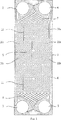
図1は、本発明による熱交換プレートの正面図である。
本発明のプレート熱交換機は、2つの媒体、好ましくは、流体の間の熱交換を行うためのものであり、薄い、主に矩形の細長い複数の熱伝達プレートが互いに隣接するように組み立てられている。また、円形のような他の形状の熱交換プレートも使用することが可能である。
図1において、従来通り、第1の熱伝達流体用の入り口ポート2及び出口ポート3と、第2の熱伝達流体用の入り口ポート4及び出口ポート5を具備している本発明による熱伝達プレート1が図示されている。密封部材6は、ポート4及び5の周りに、及びプレートの周縁に延びて、付加される熱伝達プレートと共に前記1つの熱伝達流体の流れ空間と、他の熱伝達流体が流れる通路の境界を定めている。密封部材6は、ガスケット溝に配置されたガスケットからつくられるが、溶接、ろう付けまたはのり付けのような他の公知の密封構成体を使用することができる。
熱伝達プレート1は、プレス加工によって形成された波形模様を具備しており、入口ポート2及び4と出口ポート3及び5の間に2つの配分部分7及び8と、その間に配置された主熱伝達部分9を有し、この主熱伝達部分9は、各領域が複数の平行な山及び谷を有する複数の領域10A及び10Bに分割されている。
本発明によるプレート熱交換機において、複数の同一の熱伝達プレート1が、1つのパッケージとして重ねられ、2つの隣接した熱交換プレートの一方が、他のプレートに対してそれ自身の平面内で180°回転している。このため、一方の熱伝達プレート1の前記領域10Aの山部が、第2の熱伝達プレートの前記領域10Bおける谷部によって形成された山部に当接することになる。したがって、プレート熱交換機は、互いに固定された異なる2種類の熱伝達プレートから形成される。
プレート熱交換機は、入口及び出口を有し、この入口及び出口は、基本的には熱交換プレート1の間で熱伝達流体が各熱交換プレートの一方の配分部分7から他方の配分部分8に流れの方向を有するように配置されている。この場合において、流れの方向は、基本的には熱交換プレートの長辺に平行である。プレート熱交換機のプレートの内側空間は、交互に第1の流体の流れ空間の範囲を定め、残りのプレートの内側空間は、第2の流体の流れの空間の範囲を定める。
各熱伝達プレート1の熱伝達部分9は、前記流れ方向に互いに隣接して配置された少なくとも3つの領域10A及び10Bを有する列を有し、このような列の偶数の列が流れ方向を横切るように互いに隣接して配置されている。これによって、隣接した領域10A及び10Bの各対の平行な山部及び谷部が、各領域10A及び10Bの間の仮想線に関して互いに鏡像を形成するように延びている。その結果、2つの斜めに位置した領域(10Aまたは10Bの何れか)の平行な山部及び谷部領域は同一になる。
隣接領域が鏡像を形成する複数のさらに小さい領域10A及び10Bに熱伝達部分9を分割することによって、4つのこのような領域がそれら自身を伸長するような相互の傾向に対抗して有効に作用し合い、これによって、熱伝達板をその平面内で補強する。すなわち、その山部及び谷部を平坦にすることによって、山部及び谷部に垂直な方向に領域10Aが伸長することが、山部及び谷部が前記方向に伸長しない隣接する領域10Bによって妨げられる。斜めに配置されたこの領域は、熱伝達プレートの伸長を妨げる1種の枠組を形成する。
好ましくは、各熱伝達プレート1の熱伝達部分9は、流れの方向に互いに隣接するように配置された奇数の領域10A及び10Bを有する列から成り、それによって1種類のプレートのみでのプレート熱交換機を形成することが可能である。
公知の大部分の熱伝達プレートは、本発明による複数の領域を有する熱伝達部分を具備するが、提案された熱伝達部分の分割の最も明白な効果は、大きい熱伝達プレートにおいて得られる。主に長いプレートは小さい流れのために企図され、該プレートは、隣接する各対の領域10A及び10Bの平行な山部及び谷部が流れの方向に関連して鈍角な中間の角度で伸びているいわゆる高θプレートである。
熱伝達プレートの伸長を更に防ぐために、熱伝達部分は、1つまたは複数の領域に沿って流れの方向に延びている外側に向ってプレス加工された補強リブ11を備えている。これらの補強リブが熱伝達流体のバイパスダクトを形成しないようにするために、これらの補強リブは、熱伝達部分の全長、またはその大部分の長さに沿って延びているべきではない。そうではなく、補強リブは、熱伝達部分の全体の長さにわたって互いにずれるように配置されるが、それらは、2つの熱伝達プレートが互いに対向するように配置されるときに、相互に一致するべきではない。 The present invention relates to a heat transfer plate of a plate heat exchanger for heat transfer between two fluids and to a plate heat exchanger containing several such plates. The plate heat exchanger has a plurality of thin heat transfer plates facing each other adjacent to each other and a sealing member disposed between the heat transfer plates, in which the first fluid is disposed in every other inner space of the plates. formed flow space use, the second fluid flow spaces in the remaining inner space of the plates Ru is formed. Each heat transfer plate has a waveform pattern that is pressing, has its wavy pattern and two distribution portions, and disposed heat transfer portion between them, heat transfer portion of this, each plurality It is divided into a plurality of areas having parallel ridges and valleys of the plate heat exchanger may have a direction of flow between the heat transfer plate, a plurality of row regions of the heat exchange portion extending in the direction of flow The parallel crests and troughs of each pair of adjacent regions extend so as to form a mirror image with respect to the virtual axis between the respective regions .
From GB 1468514, a plate heat exchanger is already known in which several heat transfer plates are assembled so that the fluid flows on both sides of the plate and heat is transferred between the two fluids. The heat transfer plate has a pressed corrugated portion having an upper distribution portion, a lower distribution portion, and a main heat exchange portion disposed therebetween. The heat transfer portion has a pressed corrugated portion having parallel peaks and valleys and includes a plurality of strip regions extending along the plate. Sealing members are disposed between the heat transfer plates, demarcating the flow space for the first fluid in the alternating plate spaces, and the second plate space in the second plate space. Delimits the flow space for the fluid.
From GB GB 1339542, a plate heat exchanger is already known in which a plurality of heat transfer plates arranged so that a fluid flows on each side of the plate is assembled and heat is transferred between the two fluids. . The heat exchange plate has two distribution parts and a main heat transfer part arranged between them. The heat transfer portion includes a pressed corrugated portion having parallel ridges and valleys, and a plurality of strip regions extending in the plate are formed.
Known heat exchangers have the problem that the plate is deformed, i.e. the plate bends and blows in different directions, despite having a heat transfer portion with multiple regions extending over or along the plate. . This makes it difficult to handle the plate during attachment to a conventional support bar or during welding of the plate.
This problem relies on the strong corrugated portion of the heat transfer portion of the plate allowing the plate of that portion to extend long. This problem, parallel ridges and valleys plates, when having a small angle as compared to the imaginary axis with the risk of the plate is bent about its axis, and at the same time, for example, sealing groove or fluid and out port portion This occurs particularly when the rest of the plate cannot provide sufficient rigidity to prevent deformation.
An object of the present invention is to provide a plate heat exchanger in which a corrugated pattern is formed so as to reduce the risk of deformation, and the heat transfer plate can be easily handled as compared with an already known heat transfer plate.
According to the invention, these objects are achieved by arranging in the heat transfer portion of each heat transfer plate, rows having at least three regions, connected to each other in the direction of the flow, and even rows of such rows. formation but across the direction of flow are arranged adjacent to each other, respectively a pair with it parallel ridges are and valleys of adjacent regions, the mirror images of one another with respect to the imaginary axis between the respective areas This is achieved by a plate heat exchanger of the kind mentioned in the introduction, characterized in that it extends.
The present invention is also applicable to other types of heat exchangers and has an inlet and outlet for at least two heat transfer fluids and a heat transfer portion disposed therebetween, these inlets And the outlet basically has a direction in which the fluid flows from each inlet with respect to each outlet, and the heat transfer portion is a pressed corrugation divided into a plurality of regions having parallel peaks and valleys. It has a pattern. The heat transfer portion has a row having at least three regions arranged alternately in the flow direction, such even rows are arranged adjacent to each other across the flow direction, and adjacent regions The pairs of parallel peaks and valleys also refer to the heat transfer plate of the plate heat exchanger, characterized in that they extend so as to form a mirror image with respect to the imaginary line between the regions.
The invention can be better understood with reference to the following drawings.
FIG. 1 is a front view of a heat exchange plate according to the present invention.
The plate heat exchanger of the present invention is for performing heat exchange between two media, preferably fluids, and is assembled such that a plurality of thin, primarily rectangular elongated heat transfer plates are adjacent to each other. Yes. It is also possible to use heat exchange plates having other shapes such as a circle.
In FIG. 1, a heat transfer plate according to the present invention comprising an
The
In a plate heat exchanger according to the invention, a plurality of identical
The plate heat exchanger has an inlet and an outlet, which basically transfer heat transfer fluid between the
The heat transfer portion 9 of each
By dividing the heat transfer portion 9 into a plurality of
Preferably, the heat transfer portion 9 of each
Most known heat transfer plates comprise a heat transfer part having a plurality of regions according to the invention, but the most obvious effect of the proposed division of the heat transfer part is obtained in a large heat transfer plate. Mainly long plates are intended for small flows, which extend at an intermediate angle where the parallel peaks and valleys of each adjacent pair of
In order to further prevent the heat transfer plate from extending, the heat transfer portion is provided with reinforcing
Claims (6)
前記熱伝達部分(9)は、前記流れの方向に互いに直列に連続して配置された少なくとも3つの領域(10A,10B)を有する奇数の列を含み、偶数のこのような列が、前記流れの方向を横切って互いに隣接するように配置されていることを特徴とするプレート熱交換機用の熱伝達プレート。An inlet (2, 4) and outlet (3, 5) for at least two heat transfer fluids, two distribution parts (7, 8) and a heat transfer part (9) arranged between them The inlet (2, 4) and the outlet (3, 5) are arranged so that the fluid basically has a flow direction from one of the distribution portions (7, 8) to the other, the heat transfer The portion (9) comprises a pressed corrugated pattern divided into a plurality of regions (10A, 10B) having a plurality of parallel peaks and valleys, the regions extending in the flow direction. In the same row and each pair of adjacent regions (10A, 10B), parallel ridges and valleys are respectively related to virtual lines between the regions (10A, 10B). In heat transfer plates that extend to form a mirror image of each other ,
The heat transfer portion (9) comprises an odd number of rows having at least three regions (10A, 10B) arranged in series with each other in the direction of the flow, with an even number of such rows being the flow A heat transfer plate for a plate heat exchanger, wherein the heat transfer plate is disposed adjacent to each other across the direction of the plate.
Applications Claiming Priority (3)
| Application Number | Priority Date | Filing Date | Title |
|---|---|---|---|
| SE9300570A SE505225C2 (en) | 1993-02-19 | 1993-02-19 | Plate heat exchanger and plate for this |
| SE9300570-0 | 1993-02-19 | ||
| PCT/SE1994/000040 WO1994019657A1 (en) | 1993-02-19 | 1994-01-20 | A plate heat exchanger |
Publications (2)
| Publication Number | Publication Date |
|---|---|
| JPH07506420A JPH07506420A (en) | 1995-07-13 |
| JP3675475B2 true JP3675475B2 (en) | 2005-07-27 |
Family
ID=20388970
Family Applications (1)
| Application Number | Title | Priority Date | Filing Date |
|---|---|---|---|
| JP51887294A Expired - Lifetime JP3675475B2 (en) | 1993-02-19 | 1994-01-20 | Plate heat exchanger |
Country Status (7)
| Country | Link |
|---|---|
| US (2) | US6702005B1 (en) |
| EP (1) | EP0636239B1 (en) |
| JP (1) | JP3675475B2 (en) |
| CN (1) | CN1048091C (en) |
| DE (1) | DE69422342T2 (en) |
| SE (1) | SE505225C2 (en) |
| WO (1) | WO1994019657A1 (en) |
Cited By (3)
| Publication number | Priority date | Publication date | Assignee | Title |
|---|---|---|---|---|
| KR101338727B1 (en) | 2006-06-05 | 2013-12-06 | 알파 라발 코포레이트 에이비 | Plate and gasket for plate heat exchanger |
| KR20200055119A (en) * | 2017-10-05 | 2020-05-20 | 알파 라발 코포레이트 에이비 | Plate packs for heat transfer plates and heat exchangers comprising a plurality of such heat transfer plates |
| KR20220097537A (en) * | 2019-11-26 | 2022-07-07 | 알파 라발 코포레이트 에이비 | heat transfer plate |
Families Citing this family (45)
| Publication number | Priority date | Publication date | Assignee | Title |
|---|---|---|---|---|
| SE505225C2 (en) * | 1993-02-19 | 1997-07-21 | Alfa Laval Thermal Ab | Plate heat exchanger and plate for this |
| DE10035939A1 (en) * | 2000-07-21 | 2002-02-07 | Bosch Gmbh Robert | Heat transfer device |
| ITVR20020051U1 (en) * | 2002-08-26 | 2004-02-27 | Benetton Bruno Ora Onda Spa | PLATE HEAT EXCHANGER. |
| FR2848292B1 (en) * | 2002-12-05 | 2005-03-04 | Packinox Sa | THERMAL EXCHANGER PLATE AND PLATE HEAT EXCHANGER |
| EP1654508B2 (en) * | 2003-08-01 | 2020-03-11 | MAHLE Behr GmbH & Co. KG | Heat exchanger and method for the production thereof |
| US6976531B2 (en) * | 2003-10-22 | 2005-12-20 | Dana Canada Corporation | Heat exchanger, method of forming a sleeve which may be used in the heat exchanger, and a sleeve formed by the method |
| SE0303307L (en) * | 2003-12-10 | 2004-10-19 | Swep Int Ab | Plate heat exchanger |
| JP2006125767A (en) * | 2004-10-29 | 2006-05-18 | Tokyo Institute Of Technology | Heat exchanger |
| KR20070100705A (en) * | 2005-01-18 | 2007-10-11 | 가부시키가이샤 사사꾸라 | Plate heat exchanger |
| CN100401002C (en) * | 2005-07-04 | 2008-07-09 | 缪志先 | Brazing-sheet type heat exchanger capable of using three kinds of medium to exchange heat |
| SE528879C2 (en) * | 2005-07-04 | 2007-03-06 | Alfa Laval Corp Ab | Heat exchanger plate, pair of two heat exchanger plates and plate package for plate heat exchanger |
| SE528886C2 (en) | 2005-08-26 | 2007-03-06 | Swep Int Ab | End plate |
| DE102005043952A1 (en) * | 2005-09-15 | 2007-04-05 | Danfoss A/S | Heat exchanger and method for controlling a heat exchanger |
| CN100365372C (en) * | 2005-11-16 | 2008-01-30 | 杭州钦宝制冷设备有限公司 | Three-way guidance tape typed heat exchanger |
| SE531472C2 (en) * | 2005-12-22 | 2009-04-14 | Alfa Laval Corp Ab | Heat exchanger with heat transfer plate with even load distribution at contact points at port areas |
| CN1837718A (en) * | 2006-03-09 | 2006-09-27 | 缪志先 | Fin-plate type heat exchanger |
| JP4818044B2 (en) * | 2006-09-28 | 2011-11-16 | 三洋電機株式会社 | Manufacturing method of heat exchanger |
| US20090099697A1 (en) * | 2007-06-11 | 2009-04-16 | Eair, Llc | Power Supply Switch for Dual Powered Thermostat, Power Supply for Dual Powered Thermostat, and Dual Powered Thermostat |
| CN100516758C (en) * | 2007-06-12 | 2009-07-22 | 缪志先 | Strip-free plate-fin heat exchanger |
| USD598305S1 (en) | 2008-06-11 | 2009-08-18 | Eair, Llc | Thermostat faceplate |
| SE532524C2 (en) * | 2008-06-13 | 2010-02-16 | Alfa Laval Corp Ab | Heat exchanger plate and heat exchanger assembly include four plates |
| USD679788S1 (en) * | 2008-10-07 | 2013-04-09 | Swep International Ab | Heat exchanger |
| SE533394C2 (en) * | 2008-10-15 | 2010-09-14 | Alfa Laval Corp Ab | A plate heat exchanger |
| USD610027S1 (en) | 2008-10-17 | 2010-02-16 | Eair, Llc | Touchscreen for thermostats |
| SE533205C2 (en) * | 2008-12-03 | 2010-07-20 | Alfa Laval Corp Ab | Heat |
| SE534765C2 (en) | 2010-04-21 | 2011-12-13 | Alfa Laval Corp Ab | Plate heat exchanger plate and plate heat exchanger |
| JP2012122688A (en) * | 2010-12-09 | 2012-06-28 | Hisaka Works Ltd | Heat transfer plate for plate type heat exchanger, and plate type heat exchanger |
| USD688955S1 (en) | 2012-01-24 | 2013-09-03 | Energate Inc | Thermostat unit |
| EP2920538B1 (en) * | 2012-10-16 | 2019-06-26 | The Abell Foundation Inc. | Heat exchanger including manifold |
| KR101315594B1 (en) * | 2013-07-01 | 2013-10-08 | 김훈 | Plate-type heat exchanger |
| EP2957851B1 (en) * | 2014-06-18 | 2017-05-03 | Alfa Laval Corporate AB | Heat transfer plate and plate heat exchanger comprising such a heat transfer plate |
| CN105115343A (en) * | 2015-09-14 | 2015-12-02 | 江苏远卓设备制造有限公司 | Heat exchanging plate and heat exchanger applying same |
| CN105352356B (en) * | 2015-11-10 | 2018-04-10 | 甘肃蓝科石化高新装备股份有限公司 | A kind of corrugated cardboard sheet of pressure-bearing enhancing |
| SE541591C2 (en) | 2016-02-24 | 2019-11-12 | Alfa Laval Corp Ab | A heat exchanger plate for a plate heat exchanger, and a plate heat exchanger |
| JP6093898B1 (en) * | 2016-05-27 | 2017-03-08 | 株式会社日阪製作所 | Plate heat exchanger |
| JP6097865B1 (en) * | 2016-05-27 | 2017-03-15 | 株式会社日阪製作所 | Plate heat exchanger |
| EP3396293A1 (en) * | 2017-04-26 | 2018-10-31 | Alfa Laval Corporate AB | Heat transfer plate and heat exchanger comprising a plurality of such heat transfer plates |
| US11486657B2 (en) * | 2018-07-17 | 2022-11-01 | Tranter, Inc. | Heat exchanger heat transfer plate |
| PL3650795T3 (en) * | 2018-11-07 | 2021-07-05 | Alfa Laval Corporate Ab | HEAT EXCHANGER PLATE |
| PL3657114T3 (en) * | 2018-11-26 | 2021-11-02 | Alfa Laval Corporate Ab | HEAT EXCHANGER PLATE |
| SE544426C2 (en) * | 2019-04-03 | 2022-05-24 | Alfa Laval Corp Ab | A heat exchanger plate, and a plate heat exchanger |
| CN114508955B (en) * | 2020-11-16 | 2025-01-28 | 丹佛斯有限公司 | Plate and shell heat exchanger and heat transfer plate for plate and shell heat exchanger |
| EP4015960B1 (en) * | 2020-12-15 | 2023-05-10 | Alfa Laval Corporate AB | Heat transfer plate |
| CN114894021B (en) * | 2022-03-07 | 2025-09-02 | 上海板换机械设备有限公司 | Sealed reinforced heat exchange plate and heat exchanger |
| CN116336841A (en) * | 2023-03-31 | 2023-06-27 | 佛山市顺德区鑫雷节能设备有限公司 | Plate heat exchanger and manufacturing method thereof |
Family Cites Families (19)
| Publication number | Priority date | Publication date | Assignee | Title |
|---|---|---|---|---|
| GB521285A (en) * | 1937-11-15 | 1940-05-16 | Martin Larsen | Improvements in or relating to plate heat exchanging apparatus |
| DE843094C (en) * | 1942-02-10 | 1952-07-03 | Separator Ab | Support device for the plates of heat exchangers |
| DE844600C (en) * | 1950-11-26 | 1952-07-21 | Ahlborn E Ag | Plate-shaped heat exchange device |
| US2937856A (en) * | 1956-01-26 | 1960-05-24 | Kusel Dairy Equipment Co | Plate heat exchanger |
| GB1339542A (en) * | 1970-03-20 | 1973-12-05 | Apv Co Ltd | Plate heat exchangers |
| GB1468514A (en) | 1974-06-07 | 1977-03-30 | Apv Co Ltd | Plate heat exchangers |
| IT1055235B (en) * | 1976-02-12 | 1981-12-21 | Fischer H | PLATE HEAT EXCHANGER FORMED BY PLATES HAVING DIFFERENT SHAPES |
| SE411952B (en) * | 1978-07-10 | 1980-02-11 | Alfa Laval Ab | HEAT EXCHANGER INCLUDING A MULTIPLE IN A STATUE INSERTED SWITCHING PLATE |
| SE418058B (en) * | 1978-11-08 | 1981-05-04 | Reheat Ab | PROCEDURE AND DEVICE FOR PATCHING OF HEAT EXCHANGER PLATE FOR PLATE HEAT EXCHANGER |
| SE8106221L (en) * | 1981-10-21 | 1983-04-22 | Reheat Ab | PACKING SAVINGS FOR PLATE ELEMENT FOR PLATE HEAT EXCHANGER |
| SE8504379D0 (en) * | 1985-09-23 | 1985-09-23 | Alfa Laval Thermal Ab | PLATTVEMEVEXLARE |
| DE3622316C1 (en) * | 1986-07-03 | 1988-01-28 | Schmidt W Gmbh Co Kg | Plate heat exchanger |
| AT388446B (en) * | 1986-08-29 | 1989-06-26 | Fischer Gerhard | HEAT EXCHANGER |
| SE466871B (en) | 1990-04-17 | 1992-04-13 | Alfa Laval Thermal Ab | PLATFORMERS WITH CORRUGATED PLATES WHERE THE ORIENT'S ORIENTATION IS VARIABLE IN THE FLOW DIRECTION TO SUCCESSIVELY REDUCE THE FLOW RESISTANCE |
| SE466171B (en) * | 1990-05-08 | 1992-01-07 | Alfa Laval Thermal Ab | PLATTERS WORKS AATMONISONING A PLATHER WAS ASTMINSTERING A DIVISION WAS A DIVISIONALLY DIVISED BY A FAULTY OF A PORTABLE WORTH PREPARING ACHIEVENING, |
| DE4020735A1 (en) * | 1990-06-29 | 1992-01-02 | Schmidt Bretten W Gmbh | HEAT EXCHANGER |
| JP2952261B2 (en) * | 1990-09-29 | 1999-09-20 | 株式会社日阪製作所 | Plate heat exchanger |
| DE4037969A1 (en) * | 1990-11-29 | 1992-06-04 | Schmidt Bretten W Gmbh | HEAT EXCHANGER |
| SE505225C2 (en) * | 1993-02-19 | 1997-07-21 | Alfa Laval Thermal Ab | Plate heat exchanger and plate for this |
-
1993
- 1993-02-19 SE SE9300570A patent/SE505225C2/en not_active IP Right Cessation
-
1994
- 1994-01-20 EP EP94908534A patent/EP0636239B1/en not_active Expired - Lifetime
- 1994-01-20 CN CN94190056.8A patent/CN1048091C/en not_active Expired - Lifetime
- 1994-01-20 DE DE69422342T patent/DE69422342T2/en not_active Expired - Lifetime
- 1994-01-20 WO PCT/SE1994/000040 patent/WO1994019657A1/en not_active Ceased
- 1994-01-20 JP JP51887294A patent/JP3675475B2/en not_active Expired - Lifetime
-
1999
- 1999-09-14 US US09/395,121 patent/US6702005B1/en not_active Expired - Fee Related
-
2004
- 2004-03-08 US US10/795,678 patent/US6926076B2/en not_active Expired - Fee Related
Cited By (7)
| Publication number | Priority date | Publication date | Assignee | Title |
|---|---|---|---|---|
| KR101338727B1 (en) | 2006-06-05 | 2013-12-06 | 알파 라발 코포레이트 에이비 | Plate and gasket for plate heat exchanger |
| KR20200055119A (en) * | 2017-10-05 | 2020-05-20 | 알파 라발 코포레이트 에이비 | Plate packs for heat transfer plates and heat exchangers comprising a plurality of such heat transfer plates |
| KR102379337B1 (en) | 2017-10-05 | 2022-03-29 | 알파 라발 코포레이트 에이비 | A heat transfer plate and a plate pack for a heat exchanger including a plurality of such heat transfer plates |
| US11774191B2 (en) | 2017-10-05 | 2023-10-03 | Alfa Laval Corporate Ab | Heat transfer plate and a plate pack for a heat exchanger comprising a plurality of such heat transfer plates |
| KR20220097537A (en) * | 2019-11-26 | 2022-07-07 | 알파 라발 코포레이트 에이비 | heat transfer plate |
| KR102514787B1 (en) | 2019-11-26 | 2023-03-29 | 알파 라발 코포레이트 에이비 | heat transfer plate |
| US12222174B2 (en) | 2019-11-26 | 2025-02-11 | Alfa Laval Corporate Ab | Heat transfer plate with heat transfer ridges having varying width |
Also Published As
| Publication number | Publication date |
|---|---|
| EP0636239A1 (en) | 1995-02-01 |
| US6702005B1 (en) | 2004-03-09 |
| US20040168793A1 (en) | 2004-09-02 |
| SE9300570D0 (en) | 1993-02-19 |
| EP0636239B1 (en) | 1999-12-29 |
| US6926076B2 (en) | 2005-08-09 |
| JPH07506420A (en) | 1995-07-13 |
| DE69422342D1 (en) | 2000-02-03 |
| CN1102287A (en) | 1995-05-03 |
| WO1994019657A1 (en) | 1994-09-01 |
| CN1048091C (en) | 2000-01-05 |
| DE69422342T2 (en) | 2000-05-11 |
| SE505225C2 (en) | 1997-07-21 |
| SE9300570L (en) | 1994-08-20 |
Similar Documents
| Publication | Publication Date | Title |
|---|---|---|
| JP3675475B2 (en) | Plate heat exchanger | |
| US6823934B2 (en) | Heat transfer plate and plate pack for use in a plate heat exchanger | |
| JP5307252B2 (en) | Plates and gaskets for plate heat exchangers | |
| AU2017411398B2 (en) | Heat transfer plate and heat exchanger comprising a plurality of such heat transfer plates | |
| JP3691136B2 (en) | Plate stack as heat exchanger | |
| US20230061944A1 (en) | A heat exchanger plate, and a plate heat exchanger | |
| US7044206B2 (en) | Heat exchanger plate and a plate heat exchanger | |
| JP6799680B2 (en) | Plate heat exchanger | |
| RU98100247A (en) | LAMINATED HEAT EXCHANGER CONTAINING PLASTIC ELEMENTS PLACED IN A Bundle, WHERE THE DIAGONALLY OPPOSITE ANGLES OF EACH PLATE CONTAINS A DEEPER CORNER AREAS | |
| JP3749436B2 (en) | Heat exchanger turbulence with interrupted rotation | |
| CN112146484B (en) | Plate Heat Exchanger | |
| JP4317983B2 (en) | Plate type heat exchanger | |
| DK174417B1 (en) | heat exchanger | |
| JPH0645163Y2 (en) | Plate fin type heat exchanger | |
| JP2741950B2 (en) | Stacked heat exchanger | |
| JP3543993B2 (en) | Plate heat exchanger | |
| TWI886611B (en) | A heat exchanger plate, and a plate heat exchanger | |
| CN114867979B (en) | Heat exchanger with indentations for avoiding stagnant media | |
| JPH0740852Y2 (en) | Plate fin type heat exchanger | |
| JPH0645162Y2 (en) | Plate fin type heat exchanger | |
| JPS6123474B2 (en) | ||
| JPS62178892A (en) | Heat exchanger |
Legal Events
| Date | Code | Title | Description |
|---|---|---|---|
| A602 | Written permission of extension of time |
Free format text: JAPANESE INTERMEDIATE CODE: A602 Effective date: 20040202 |
|
| A521 | Request for written amendment filed |
Free format text: JAPANESE INTERMEDIATE CODE: A523 Effective date: 20040406 |
|
| A711 | Notification of change in applicant |
Free format text: JAPANESE INTERMEDIATE CODE: A711 Effective date: 20040406 |
|
| TRDD | Decision of grant or rejection written | ||
| A01 | Written decision to grant a patent or to grant a registration (utility model) |
Free format text: JAPANESE INTERMEDIATE CODE: A01 Effective date: 20050329 |
|
| A61 | First payment of annual fees (during grant procedure) |
Free format text: JAPANESE INTERMEDIATE CODE: A61 Effective date: 20050426 |
|
| R150 | Certificate of patent or registration of utility model |
Free format text: JAPANESE INTERMEDIATE CODE: R150 |
|
| FPAY | Renewal fee payment (event date is renewal date of database) |
Free format text: PAYMENT UNTIL: 20090513 Year of fee payment: 4 |
|
| FPAY | Renewal fee payment (event date is renewal date of database) |
Free format text: PAYMENT UNTIL: 20100513 Year of fee payment: 5 |
|
| FPAY | Renewal fee payment (event date is renewal date of database) |
Free format text: PAYMENT UNTIL: 20110513 Year of fee payment: 6 |
|
| FPAY | Renewal fee payment (event date is renewal date of database) |
Free format text: PAYMENT UNTIL: 20110513 Year of fee payment: 6 |
|
| FPAY | Renewal fee payment (event date is renewal date of database) |
Free format text: PAYMENT UNTIL: 20120513 Year of fee payment: 7 |
|
| FPAY | Renewal fee payment (event date is renewal date of database) |
Free format text: PAYMENT UNTIL: 20130513 Year of fee payment: 8 |
|
| FPAY | Renewal fee payment (event date is renewal date of database) |
Free format text: PAYMENT UNTIL: 20130513 Year of fee payment: 8 |
|
| R250 | Receipt of annual fees |
Free format text: JAPANESE INTERMEDIATE CODE: R250 |
|
| EXPY | Cancellation because of completion of term |