JP3674218B2 - Light bulbs and lighting fixtures - Google Patents
Light bulbs and lighting fixtures Download PDFInfo
- Publication number
- JP3674218B2 JP3674218B2 JP04502197A JP4502197A JP3674218B2 JP 3674218 B2 JP3674218 B2 JP 3674218B2 JP 04502197 A JP04502197 A JP 04502197A JP 4502197 A JP4502197 A JP 4502197A JP 3674218 B2 JP3674218 B2 JP 3674218B2
- Authority
- JP
- Japan
- Prior art keywords
- bulb
- filament
- valve
- temperature
- coiled filament
- Prior art date
- Legal status (The legal status is an assumption and is not a legal conclusion. Google has not performed a legal analysis and makes no representation as to the accuracy of the status listed.)
- Expired - Fee Related
Links
Images


Classifications
-
- Y—GENERAL TAGGING OF NEW TECHNOLOGICAL DEVELOPMENTS; GENERAL TAGGING OF CROSS-SECTIONAL TECHNOLOGIES SPANNING OVER SEVERAL SECTIONS OF THE IPC; TECHNICAL SUBJECTS COVERED BY FORMER USPC CROSS-REFERENCE ART COLLECTIONS [XRACs] AND DIGESTS
- Y02—TECHNOLOGIES OR APPLICATIONS FOR MITIGATION OR ADAPTATION AGAINST CLIMATE CHANGE
- Y02B—CLIMATE CHANGE MITIGATION TECHNOLOGIES RELATED TO BUILDINGS, e.g. HOUSING, HOUSE APPLIANCES OR RELATED END-USER APPLICATIONS
- Y02B20/00—Energy efficient lighting technologies, e.g. halogen lamps or gas discharge lamps
Description
【0001】
【発明の属する技術分野】
本発明は発光源として用いられるコイル状フィラメントをバルブ内に封装した電球およびこの電球を装着した照明器具に関する。
【0002】
【従来の技術】
電球はガラスバルブ内にアルゴンなどの不活性ガスとともに、タングステン素線をコイル状に巻回したものをさらに巻回した二重コイル状のフィラメントを発光源として封装している。そして、点灯により上記コイル状フィラメントが徐々に蒸発して細るなどの原因で断線するまでが寿命とされ、汎用の電球では定格寿命が1000時間程度となっている。
【0003】
また、電球の一種のハロゲン電球は、バルブ内に不活性ガスとともに微量のハロゲン族元素(I、Br、Cl、F)が封入され、コイル状フィラメントから蒸発したタングステンとハロゲン族元素との間の化学的な循環反応(ハロゲンサイクル)を利用している。
【0004】
すなわち、フィラメントから蒸発したタングステンをハロゲンサイクルを利用して、フィラメントに戻しそのやせ細りを防ぐようにしている。しかし、蒸発したタングステンが元の位置に戻るならば寿命は半永久的となって好ましいが、実際には完全に元の位置に戻らずに、フィラメントに徐々にやせ細りの部分が生じついには断線に至るが、汎用の電球に比べ光束を同じとすれば寿命を2倍の2000時間まで向上させることができる。
【0005】
また、このハロゲン電球は、ハロゲンサイクルを活発化するためバルブの温度が250℃以上となるよう設計されているとともに、フィラメントの蒸発を抑制するため不活性ガスの封入圧力が高い、小形で高効率のものである。
【0006】
そして、近年に至り、さらにの高効率化および省エネルギ化の一環として電球分野においても種々の工夫がなされている。ハロゲン電球においては、バルブの表面に多層光干渉膜からなる可視光透過赤外線反射膜を形成するとともに、バルブ軸に沿ってコイル状フィラメントを配設することによって、フィラメントから放射された赤外線をこの反射膜で効率よく反射してフィラメントに帰還させ、これによってフィラメントを加熱して発光効率を高めることが行われている。
【0007】
また、この種ハロゲン電球で可視光透過赤外線反射膜を形成していないバルブ内にバルブの軸に沿ってコイル状フィラメントを配設したものにおいて、定格点灯時のフィラメントの軸方向における各部温度は図7に点線Aで示すようにフィラメントの中央部が最も高温な山形の分布をなしている。また、可視光透過赤外線反射膜を形成した直管形などのバルブ内にバルブの軸に沿ってフィラメントを配設したものにおいても、図7に実線Bで示すようにフィラメントの中央部が最も高温な山形で、しかも、赤外線反射膜の作用で膜なしに比べて相対的に高い温度の分布をなしている。
【0008】
上述したように赤外線反射膜の有無に拘らず、コイル状フィラメントの中央部が最高温度となるのは、端部は放熱が多いが中央部は両側からの伝導熱や放射熱を受け温度が高まるためで、通常からこのフィラメントの中央部における断線が多い。この断線は、フィラメントに欠陥などがあるとその部分が過熱して高温度になるホットスポットを生じるためで、フィラメントの中央部は特に高温度となるためここに欠陥などがあるとホットスポットが発生し易い。そして、このホットスポットはフィラメントを形成するタングステンが蒸発やスパッタされて、他の部分より早くやせ細って電気抵抗値が上がる結果、ますます過熱され早期に断線してしまうものである。
【0009】
そこで、このコイル状フィラメント中央部の昇温を避け、フィラメント各部位における温度差をできるだけ少なくする手段として、フィラメントの中央部と端部とでそのコイルのピッチや径を変えたり、また、可視光透過赤外線反射膜を形成したものでは上記のほか被膜の厚さを部分的に変えたりあるいはバルブの形状を変えバルブ部位によって反射特性を変えるなどのことが行なわれている。
【0010】
【発明が解決しようとする課題】
しかし、上述したように手段を講じても定格寿命以下でコイル状フィラメントの中央部に断線を生じる電球があり、本発明者はこのフィラメントの断線について究明をした。
【0011】
本発明者の考察によると、点灯時にコイル状フィラメントの温度が高温度となる部分においてフィラメントの隣接部位との温度差が大きいと、すなわち、温度勾配の大きい部分に断線が多いことを見出だした。
【0012】
これは、上記ホットスポットの発生にも関係するかも知れないが、点灯中のコイル状フィラメントにおいて高温度となる部分は、フィラメント素線を構成するタングステン原子が移動し、不純物の蒸発や消失によつてポア(空孔)が発生し、これが成長してフィラメントの断面積を局部的に小さくし電気的抵抗値を増加する結果、この部分が過熱し高温となって断線に至ると考えられる。
【0013】
そこで、本発明はコイル状フィラメント点灯時に高温度(2500K以上)となる部分において、延在するフィラメントの温度勾配を規制することによって、タングステン素線中にポア(空孔)の生じ難い長寿命の電球およびこの電球を装着した照明器具を提供することを目的とする。
【0014】
【課題を解決するための手段】
本発明の請求項1に記載の電球は、ガラスバルブと、バルブ内に配設されたリード部材と、バルブ内に封入された不活性ガスと、リード部材に継線されたコイル状フィラメントとを具備し、定格点灯時にコイル状フィラメントが2500K以上となる部位のタングステン素線における温度勾配の最大値が2.5度/mm以下であることを特徴とする。
【0015】
電球点灯時にコイル状フィラメントの2500K以上となる部分における温度分布を改良して、フィラメント延在方向の温度勾配を小さくして急激な温度差部分をなくし、タングステン素線中にポア(空孔)が生じ難く、フィラメントに局部的な高温部の発生がない。
【0016】
そして、上記でコイル状に巻回されたものを展開したタングステン素線における温度勾配が2.5度(℃)/mmを越えると、点灯中タングステン素線中にポア(空孔)が生じ易く、その部分が過熱し高温となって早期に断線に至るという問題がある。
【0017】
本発明の請求項2に記載の電球は、ガラスバルブと、バルブの表面に形成された可視光透過赤外線反射膜と、バルブ内に配設されたリード部材と、バルブ内に封入された不活性ガスと、バルブ中心軸に沿うようリード部材に継線されたコイル状フィラメントとを具備し、定格点灯時にコイル状フィラメントが2500K以上となる部位のタングステン素線における温度勾配の最大値が2.5度/mm以下であることを特徴とする。
【0018】
可視光透過赤外線反射膜を有する電球は、赤外線反射膜により赤外線をフィラメントに戻しフィラメントを加熱しているので、被膜を形成していない電球に比べてフィラメントの温度が高くなるが、上記請求項1に記載したと同様な作用によりフィラメントに局部的な高温部の発生がない。
【0019】
なお、可視光透過赤外線反射膜の形成はバルブの外表面に限らず、バルブの内表面であってもよく、内外表面の少なくとも一方に形成してあればよい。また、可視光透過赤外線反射膜の材料として、高屈折率層膜には二酸化チタン(TiO2 )、五酸化タンタル(Ta2 O5 )、二酸化ジルコン(ZrO2 )、二酸化亜鉛(ZnO2 )など、低屈折率層膜としては二酸化ケイ素(SiO2 )やふっ化マグネシウム(MgF)などがある。
【0020】
本発明の請求項3に記載の電球は、バルブ形状が直管状、楕円状、長円状、球状のうちから選ばれた少なくとも一種を有することを特徴とする。
【0021】
バルブ形状を適宜選ぶことにより、バルブの表面に形成した可視光透過赤外線反射膜の反射特性を変化させて赤外線の戻りを調整しコイル状フィラメントの温度分布の均一化をはかることができる。
【0022】
また、バルブの形状は、楕円状や球状部の間に直管状部を連設するなど複数の形状が組合わせられたものであってもよく、フィラメントへの赤外線の戻りを平均的によくするよう設計するのが好ましい。
【0023】
本発明の請求項4に記載の電球は、バルブ内にハロゲンガスおよび不活性ガスが封入されていることを特徴とする。
【0024】
ハロゲン電球に適用して、上記請求項1ないし3に記載したと同様な作用を奏する。
【0025】
本発明の請求項5に記載の照明器具は、器具本体と、器具本体に配設されたソケットと、ソケットに装着された請求項1ないし4のいずれか一記載の電球とを具備していることを特徴とする。
【0026】
上記請求項1ないし4に記載の作用を奏する電球は、フィラメントに局部的な高温部の発生がなく短寿命とならないので、電球交換頻度の低い照明器具が得られる。
【0027】
【発明の実施の形態】
以下、本発明の実施の形態を図面を参照して説明する。図1は小形投光用のハロゲン電球Lの一部断面正面図、図2は二重コイル状フィラメントを拡大した一部切欠正面図、図3は図1の電球Lをバルブ軸が水平な状態で点灯したときの二重コイル状フィラメントの温度分布を示す。
【0028】
図中1は、石英ガラスからなる回転楕円形状のバルブ、2はバルブ1の一端部に形成された圧潰封止部、3はバルブ1の他端部に設けられた排気管、4はバルブ1の外表面に形成されている可視光透過赤外線反射膜、5は圧潰封止部2に耐熱性接着剤51を介し接合された口金である。
【0029】
上記バルブ1は、長軸長さ2aが18.0mm、短軸長さ2bが14.0mm、焦点間距離が11.3mm、両端部の円筒部径が10.5mmであり、(x2 /a2 )+(y2 /b2 )=1の周を有している。そして、バルブ1の外表面に形成された可視光透過赤外線反射膜(以下、赤反膜と称する。)4は、高屈折率層を形成する二酸化チタン(TiO2 )膜と、低屈折率層を形成する二酸化ケイ素(SiO2 )膜とを交互に積層した多層干渉膜からなる。
【0030】
また、バルブ1の内部には二重コイル状のフィラメント6およびハロゲン(CH2 Br2 …400ppm)を含む不活性ガス(Ar90容量%、残部N)が約3気圧封入してある。上記コイル状フィラメント6は両端の足部63,63がリード部材を形成する内部リード線71,71に継線され、バルブ1の中心軸に沿って配設されている。また、この内部リード線71,71の他端はバルブ1の端部の圧潰封止部2内に封止されたモリブデン箔72,72に接続されている。また,各モリブデン箔72,72の他端側には外部リード線73,73が接続されている。また、8はコイル状フィラメント6の中間部を支持するアンカである。また、このハロゲン電球Lはたとえば定格が110V65Wで、上記二重コイル状フィラメント6の構成(コイルデータ)は、MGが約8.92のタングステン素線61を、内径D1が約0.30mm、ピッチP1が約0.109mmで約553ターン巻回した長さが約60.3mmの単コイル62を、さらに、内径D2が約0.80mm、ピッチP2が約0.82mmで両端部に約8mmの単コイルからなる足部63,63を残して約11ターン巻回した二重コイル64部の長さL2が約9mmで、その全長CLを約25mmとした。
【0031】
上記構成の電球Lを点灯すると、バルブ1の中心軸上に配設した二重コイル状のフィラメント6から放射した光のうち可視光はバルブ1および赤反膜4を透過してバルブ1外方へと放射される。また、フィラメント6から放射した赤外線は赤反膜4で反射されてフィラメント6に戻りフィラメント6を加熱する。なお、このフィラメント6と赤反膜4との間での赤外線の授受は反復行われる。
【0032】
そして、上記では赤反膜4を形成したバルブ1の形状を楕円面としてあるので、赤反膜4からの反射赤外線はフィラメント6の中心部に集中して戻らず各部分に分散されて、点灯時のフィラメント6の温度は図3に示すような分布となる。すなわち、この場合のフィラメント6の温度分布は図3に示すように、全長に亘りほぼ均一になり、高温のホットスポットの発生はなく、中心部の温度を下げ部分的な過熱を防ぐことができる。
【0033】
したがって、この実施の形態によれば、コイル状フィラメント6の材料であるタングステンの局部的な蒸発がなく早期に細まって断線することを防ぎ、長寿命の電球Lを提供できる。
【0034】
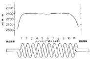
そして、上記構成としたフィラメント6の各部位の温度をさらに詳細に検討すると、端部を除くフィラメント6中間部の2500K以上となる高温部における隣接部の温度差(温度勾配)が従来品に比べて小さくなっていた。すなわち、図4に示すように、バルブ1軸を水平にして点灯した電球Lの二重コイル64の中間部の或るターンT1と隣接するターンT2とのほぼ同一位置E,F点にあるタングステン素線61の温度は一方が約2800Kに対して他方は約2750Kで、その温度差ΔTは約50℃であった。そして、この二重コイル64の1ターンは、コイル部64および62を巻き戻しタングステン素線61として展開した長さPLは約41.3mmあり、その温度勾配(温度差ΔT/展開した長さPL)は、タングステン素線61の1mm当たり1.21℃であった。
【0035】
したがって、点灯中のコイル状フィラメント6において2500K以上の高温度となる二重コイル64部分の温度勾配が大きいと、フィラメント素線中にタングステン原子の移動、蒸発や不純物の消失によるポア(空孔)の発生が起き易く、フィラメント6の断面積を小さくして電気的抵抗値を増す結果、早期にこの部分が過熱し高温となって断線となる短寿命を生じるが、上記のように温度勾配を小さくすることによって適正な寿命を得ることができた。
【0036】
また、本発明者の実験によれば定格が100/110V65Wの上記品種において、コイル状フィラメント6が2500K以上の高温度となる部分の温度勾配(温度差ΔT/展開した長さPL)が、コイル部を展開した素線61部位で測定して最大で2.5度(℃)/mm以下であればよかった。
また、二重コイル64部分でも1ターン目や11ターン目の端部では温度勾配が大きくても点灯時のフィラメント6温度が2500K未満であれば、タングステン原子の移動、蒸発や不純物の消失によるポア(空孔)が生じないので、局部的なやせ細りがなくこの部分からの断線はなかった。
【0037】
なお、上記コイル状フィラメント6の温度勾配の測定は、パイロメータを用い行った。上記タングステン素線61部分では二重コイルの隣り合うターンのほぼ同一箇所が展開した場合の38mm離れた位置である。
【0038】
そして、上記実施の形態では110V65Wのハロゲン電球Lについて述べたが、本発明は定格が100/110V40〜100Wの電球に適用して、コイル状フィラメント6の温度勾配を2.5度/mm以下と抑えることにより、上記と同様な作用効果が得られた。
【0039】
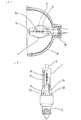
したがって、フィラメント6設計にあたり、上記のような温度勾配を考慮したフィラメントデータとすることによって、電球Lの短寿命の発生を防止できる。 また、図5は本発明の実施の形態を示す照明器具9である。この図5中、91は天井面などに取着される基台、92は支持ポール、93はポール92の先端に回動自在に取付けられた自在継手、94はこの自在継手が設けられた器具本体、95は器具本体の前方開口部内に設けられた反射体で、この反射体95の部分にはソケット(図示しない。)が配設され、このソケット(図示しない。)にたとえば図1に示すハロゲン電球Lの口金5を装着することにより照明器具9が構成されている。
【0040】
この器具9のソケット(図示しない。)へ装着された電球Lは、フィラメント6に通電して点灯する。そして、上述した電球Lと同様な作用をして定格寿命を全うすることができる。
【0041】
なお、本発明は上記実施の形態に限定されない。たとえば、ランプはバルブの一端に封止部を形成した投光用ハロゲン電球に限らず、他の用途やハロゲンを封入していない種類の電球でもよく、また、封止部がバルブの両端部に設けてあるものでもよい。また、封止部は圧潰封止に限らず、バルブを収縮して形成した封止部でもよく、また、モリブデン箔などの金属箔に限らず、線状の封着部材を用いるものであってもよい。
【0042】
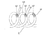
また、電球は、図6(a)に示すように反射鏡8の基部81内に電球Lの圧潰封止部2を配置して耐熱性接着剤82を介して一体に接合したり、あるいは図示しないが反射鏡の基部近傍に配設したソケットに電球の口金部を装着して一体的にした反射鏡付き電球に適用することもできる。
【0043】
また、バルブ形状は楕円状に限らず、図6(b)に示す直管状のものや長円状、や球状などから選ばれた少なくとも一種を有するものであって、楕円状や球状部の間に直管状部を設けるなど複数の形状が組合わせられた複合形状であってもよい。また、バルブのガラス材質は石英ガラスに限らず、所要の透光性と光屈折率と耐熱性を併有するものであれば他の硬質や軟質のガラス材質であってもよい。 さらに、ガラスバルブの表面に可視光透過赤外線反射膜が形成してあっても、形成してなくても構わない。
【0044】
さらにまた、照明器具も、上記実施の形態に示したものに限らず、他の構造のものであってもよい。
【0045】
【発明の効果】
請求項1の発明によれば、フィラメント延在方向の温度勾配が小さく急激な温度差部分がなく、短寿命を生じることがないとともに寿命のばらつきが小さい電球を提供できる。
【0046】
また、請求項2および3の発明によれば、バルブの表面に可視光透過赤外線反射膜を形成した電球において、上記請求項1の記載と同様な効果を奏する。
【0047】
また、請求項4の発明によれば、ハロゲン電球に適用して上記請求項1ないし3の記載と同様な効果を奏する。
【0048】
さらに、請求項5の発明によれば、請求項1ないし4のいずれか一記載の電球を備えているので、電球の短寿命がない、電球交換頻度の低いメンテナンスの容易な照明器具を提供することができる。
【図面の簡単な説明】
【図1】本発明の実施の形態を示す投光用ハロゲン電球の一部断面正面図である。
【図2】二重コイル状フィラメントを拡大した一部切欠正面図である。
【図3】図1の電球Lをバルブ軸が水平な状態で点灯したときのフィラメントの温度分布を示す説明図である。
【図4】二重コイルフィラメントの隣接するターンの温度勾配を説明する説明図である。
【図5】本発明の実施の形態を示す照明器具の斜視図である。
【図6】(a)および(b)は、本発明の他の実施の形態を示すハロゲン電球の一部断面正面図である。
【図7】従来の電球をバルブ軸が水平な状態で点灯したときのフィラメントの温度分布を示す説明図である。
【符号の説明】
L:電球
1:バルブ
2:圧潰封止部
4:可視光透過赤外線反射膜(赤反膜)
6:コイル状フィラメント
61:タングステン素線
62:単コイル
64:二重コイル
7:リード部材
9:照明器具
94:器具本体[0001]
BACKGROUND OF THE INVENTION
The present invention relates to a luminaire fitted with bulb and the bulb coiled filament was sealed instrumentation within the valve to be used as a light emitting source.
[0002]
[Prior art]
The light bulb is sealed with a double coiled filament in which a tungsten wire is wound in a coil shape together with an inert gas such as argon in a glass bulb as a light source. And it is a lifetime until it breaks due to the coiled filament gradually evaporating and thinning due to lighting, and a general-purpose light bulb has a rated life of about 1000 hours.
[0003]
In addition, a kind of halogen bulb is a bulb in which a small amount of a halogen group element (I, Br, Cl, F) is enclosed in the bulb together with an inert gas, and between tungsten and the halogen group element evaporated from the coiled filament. A chemical circulation reaction (halogen cycle) is used.
[0004]
That is, tungsten evaporated from the filament is returned to the filament using a halogen cycle to prevent the thinning. However, if the evaporated tungsten returns to its original position, the lifetime is preferably semi-permanent, but in practice it does not return completely to its original position, but the filament gradually fades and eventually breaks. However, if the luminous flux is the same as that of a general-purpose light bulb, the lifetime can be doubled to 2000 hours.
[0005]
In addition, this halogen bulb is designed to have a bulb temperature of 250 ° C. or higher in order to activate the halogen cycle, and it is small and highly efficient with a high inert gas filling pressure to suppress filament evaporation. belongs to.
[0006]
In recent years, various devices have been devised in the field of electric bulbs as part of higher efficiency and energy saving. In a halogen bulb, a visible light transmitting infrared reflecting film composed of a multilayer optical interference film is formed on the surface of the bulb, and a coiled filament is disposed along the bulb axis to reflect infrared rays emitted from the filament. The light is efficiently reflected by the film and returned to the filament, thereby heating the filament to increase the light emission efficiency.
[0007]
Further, in this type of halogen bulb, in which a visible light transmitting infrared reflective film is not formed and a coiled filament is disposed along the axis of the bulb, the temperature of each part in the axial direction of the filament during rated lighting is shown in FIG. As shown by the dotted line A in FIG. 7 , the central part of the filament has the highest temperature distribution. Further, even in a straight tube or the like in which a visible light transmitting infrared reflecting film is formed, a filament is disposed along the axis of the bulb, as shown by a solid line B in FIG. In addition, the distribution of the temperature is relatively high as compared with the case where no film is formed due to the action of the infrared reflecting film.
[0008]
As described above, regardless of the presence or absence of the infrared reflecting film, the central portion of the coiled filament has the highest temperature because the end portion has a large amount of heat dissipation, but the central portion receives the heat of conduction and radiant heat from both sides and the temperature rises. For this reason, there are usually many breaks in the center of the filament. This disconnection is because if there is a defect in the filament, it will overheat and generate a hot spot where the temperature becomes high, and the center part of the filament will be at a particularly high temperature. Easy to do. This hot spot is formed by evaporating or sputtering tungsten forming the filament, thinning faster than other portions and increasing the electric resistance, resulting in more overheating and early disconnection.
[0009]
Therefore, as a means of avoiding the temperature rise in the central part of the coiled filament and reducing the temperature difference in each part of the filament as much as possible, the coil pitch and diameter are changed between the central part and the end part of the filament, and visible light In the case where a transmission infrared reflection film is formed, in addition to the above, the thickness of the coating is partially changed, or the shape of the bulb is changed to change the reflection characteristics depending on the bulb portion.
[0010]
[Problems to be solved by the invention]
However, as described above, there is a light bulb that causes a break in the center of the coiled filament within the rated life even when the measures are taken, and the present inventor has investigated the breakage of the filament.
[0011]
According to the inventor's consideration, it has been found that when the temperature of the coiled filament becomes high during lighting, the temperature difference from the adjacent portion of the filament is large, that is, there are many disconnections in the portion where the temperature gradient is large. .
[0012]
This may be related to the occurrence of the hot spot, but in the coiled filament that is lit, the portion of the coil filament that is at a high temperature is moved by the tungsten atoms that make up the filament wire, and the evaporation and disappearance of impurities. As a result, pores (holes) are generated and grow to locally reduce the cross-sectional area of the filament and increase the electrical resistance value. As a result, this portion is overheated and becomes high temperature, leading to disconnection.
[0013]
Therefore, the present invention has a long service life in which pores (holes) are not easily generated in the tungsten wire by regulating the temperature gradient of the extending filament in the portion where the temperature is high (at 2500 K or more) when the coiled filament is turned on. An object of the present invention is to provide a light bulb and a lighting fixture equipped with the light bulb.
[0014]
[Means for Solving the Problems]
A light bulb according to
[0015]
To improve your Keru temperature distribution at a portion to be the least 2500K coiled filament during bulb lit, to reduce the temperature gradient of the filament extending direction eliminate sudden temperature difference portion, while the tungsten wire pores (vacancy ) Hardly occur, and there is no local high-temperature portion in the filament.
[0016]
When the temperature gradient in the tungsten wire developed from the coiled wire described above exceeds 2.5 degrees (° C.) / Mm, pores (holes) are easily generated in the tungsten wire during lighting. There is a problem that the part is overheated and becomes a high temperature, leading to disconnection at an early stage.
[0017]
The light bulb according to
[0018]
In the light bulb having the visible light transmitting infrared reflection film, since the infrared ray is returned to the filament by the infrared reflection film and the filament is heated, the temperature of the filament is higher than that of the light bulb without the coating. The filament does not generate a local high temperature part by the same action as described in the above.
[0019]
The formation of the visible light transmitting infrared reflection film is not limited to the outer surface of the bulb, but may be the inner surface of the bulb, as long as it is formed on at least one of the inner and outer surfaces. In addition, as a material for the visible light transmitting infrared reflecting film, titanium dioxide (TiO 2 ), tantalum pentoxide (Ta 2 O 5 ), zircon dioxide (ZrO 2 ), zinc dioxide (ZnO 2 ), etc. are used for the high refractive index layer film. Examples of the low refractive index layer film include silicon dioxide (SiO 2 ) and magnesium fluoride (MgF).
[0020]
The bulb according to
[0021]
By choosing the valve shape appropriately as possible out that by changing the reflection characteristic of the visible light transmittance infrared reflecting film formed on the surface of the valve made uniform temperature distribution of the adjusted coil filament infrared return.
[0022]
The shape of the bulb may be a combination of a plurality of shapes such as an elliptical shape or a straight tubular portion connected between the spherical portions, and improves the return of infrared rays to the filament on average. It is preferable to design as follows.
[0023]
The bulb according to
[0024]
When applied to a halogen light bulb, the same effects as described in the first to third aspects of the present invention are achieved.
[0025]
A lighting fixture according to a fifth aspect of the present invention includes a fixture main body, a socket disposed in the fixture main body, and the light bulb according to any one of
[0026]
Since the light bulb having the effects described in
[0027]
DETAILED DESCRIPTION OF THE INVENTION
Hereinafter, embodiments of the present invention will be described with reference to the drawings. 1 is a partially sectional front view of a small-sized light-emitting halogen bulb L, FIG. 2 is a partially cutaway front view in which a double coil filament is enlarged, and FIG. 3 is a state in which the bulb L of FIG. The temperature distribution of the double coil filament when turned on is shown.
[0028]
In the figure, 1 is a spheroidal valve made of quartz glass, 2 is a crushing sealing part formed at one end of the
[0029]
The
[0030]
Further, inside the
[0031]
When the light bulb L having the above configuration is turned on, visible light out of the light emitted from the double-coiled
[0032]
In the above, since the shape of the
[0033]
Therefore, according to this embodiment, there is no local evaporation of tungsten, which is the material of the coiled
[0034]
When the temperature of each part of the
[0035]
Therefore, when the temperature gradient of the
[0036]
Further, according to the experiment of the present inventor, in the above-mentioned varieties having a rating of 100 / 110V65W, the temperature gradient (temperature difference ΔT / expanded length PL) of the portion where the coiled
Further, even in the
[0037]
The temperature gradient of the coiled
[0038]
And although the 110V65W halogen light bulb L was described in the above embodiment, the present invention is applied to a light bulb having a rating of 100 / 110V40-100W, and the temperature gradient of the coiled
[0039]
Therefore, when the
[0040]
The light bulb L attached to the socket (not shown) of the instrument 9 is turned on by energizing the
[0041]
The present invention is not limited to the above embodiment. For example, the lamp is not limited to a light emitting halogen bulb in which a sealing portion is formed at one end of the bulb, but may be a bulb that does not enclose halogen for other uses or has a sealing portion at both ends of the bulb. It may be provided. Further, the sealing portion is not limited to the crushing sealing, and may be a sealing portion formed by contracting the valve, and is not limited to a metal foil such as a molybdenum foil, but uses a linear sealing member. Also good.
[0042]
Further, as shown in FIG. 6 (a), the light bulb is integrally joined via a heat-resistant adhesive 82 by disposing the crushing sealing
[0043]
Further, the bulb shape is not limited to an elliptical shape, and has at least one selected from a straight tubular shape, an oval shape, a spherical shape, and the like shown in FIG. It may be a composite shape in which a plurality of shapes are combined, such as providing a straight tubular portion. The glass material of the bulb is not limited to quartz glass, but may be other hard or soft glass material as long as it has required translucency, light refractive index, and heat resistance. Furthermore, the visible light transmitting infrared reflecting film may or may not be formed on the surface of the glass bulb.
[0044]
Furthermore, the lighting fixtures are not limited to those shown in the above embodiment, and may have other structures.
[0045]
【The invention's effect】
According to the present invention, there is no temperature gradient is small sharp temperature difference portion of the filament extending direction, can provide a light bulb variation in lifetime is small with never produce short-lived.
[0046]
Further, according to the inventions of
[0047]
According to the invention of
[0048]
Furthermore, according to the invention of
[Brief description of the drawings]
FIG. 1 is a partial cross-sectional front view of a halogen lamp for projection showing an embodiment of the present invention.
FIG. 2 is a partially cutaway front view in which a double coiled filament is enlarged.
FIG. 3 is an explanatory diagram showing a temperature distribution of a filament when the light bulb L of FIG. 1 is lit with the bulb axis being horizontal.
FIG. 4 is an explanatory diagram for explaining a temperature gradient of adjacent turns of a double coil filament.
FIG. 5 is a perspective view of a lighting fixture showing an embodiment of the present invention.
FIGS. 6A and 6B are partial cross-sectional front views of a halogen light bulb showing another embodiment of the present invention.
FIG. 7 is an explanatory diagram showing a temperature distribution of a filament when a conventional light bulb is lit with the bulb axis being horizontal.
[Explanation of symbols]
L: Light bulb 1: Bulb 2: Crushing sealing part 4: Visible light transmitting infrared reflecting film (red film)
6: Coiled filament 61: Tungsten strand 62: Single coil 64: Double coil 7: Lead member 9: Lighting fixture 94: Appliance main body
Claims (5)
バルブ内に配設されたリード部材と;
バルブ内に封入された不活性ガスと;
リード部材に継線されたコイル状フィラメントと;
を具備し、定格点灯時にコイル状フィラメントが2500K以上となる部位のタングステン素線における温度勾配の最大値が2.5度/mm以下であることを特徴とする電球。With a glass bulb;
A lead member disposed within the valve;
An inert gas enclosed in a valve;
A coiled filament connected to the lead member ;
Bulb comprising, wherein the maximum value is 2.5 degrees / mm or less der Rukoto temperature gradient in the tungsten wire of the portion coiled filament during rated lighting is more than 2500K to.
バルブの表面に形成された可視光透過赤外線反射膜と;
バルブ内に配設されたリード部材と;
バルブ内に封入された不活性ガスと;
バルブ中心軸に沿うようリード部材に継線されたコイル状フィラメントと;
を具備し、定格点灯時にコイル状フィラメントが2500K以上となる部位のタングステン素線における温度勾配の最大値が2.5度/mm以下であることを特徴とする電球。With a glass bulb;
A visible light transmitting infrared reflecting film formed on the surface of the bulb;
A lead member disposed within the valve;
An inert gas enclosed in a valve;
A coiled filament connected to the lead member along the central axis of the valve ;
Bulb comprising, wherein the maximum value is 2.5 degrees / mm or less der Rukoto temperature gradient in the tungsten wire of the portion coiled filament during rated lighting is more than 2500K to.
器具本体に配設されたソケットと;
ソケットに装着された請求項1ないし4のいずれか一に記載の電球と;
を具備していることを特徴とする照明器具。An instrument body;
A socket disposed in the instrument body;
A light bulb as claimed in any one of claims 1 to 4 mounted in a socket;
The lighting fixture characterized by comprising.
Priority Applications (1)
| Application Number | Priority Date | Filing Date | Title |
|---|---|---|---|
| JP04502197A JP3674218B2 (en) | 1997-02-28 | 1997-02-28 | Light bulbs and lighting fixtures |
Applications Claiming Priority (1)
| Application Number | Priority Date | Filing Date | Title |
|---|---|---|---|
| JP04502197A JP3674218B2 (en) | 1997-02-28 | 1997-02-28 | Light bulbs and lighting fixtures |
Publications (2)
| Publication Number | Publication Date |
|---|---|
| JPH10241636A JPH10241636A (en) | 1998-09-11 |
| JP3674218B2 true JP3674218B2 (en) | 2005-07-20 |
Family
ID=12707694
Family Applications (1)
| Application Number | Title | Priority Date | Filing Date |
|---|---|---|---|
| JP04502197A Expired - Fee Related JP3674218B2 (en) | 1997-02-28 | 1997-02-28 | Light bulbs and lighting fixtures |
Country Status (1)
| Country | Link |
|---|---|
| JP (1) | JP3674218B2 (en) |
Families Citing this family (1)
| Publication number | Priority date | Publication date | Assignee | Title |
|---|---|---|---|---|
| DE102006060025A1 (en) * | 2006-12-19 | 2008-06-26 | Patent-Treuhand-Gesellschaft für elektrische Glühlampen mbH | Welding aid for a filament |
-
1997
- 1997-02-28 JP JP04502197A patent/JP3674218B2/en not_active Expired - Fee Related
Also Published As
| Publication number | Publication date |
|---|---|
| JPH10241636A (en) | 1998-09-11 |
Similar Documents
| Publication | Publication Date | Title |
|---|---|---|
| JPH10501368A (en) | Incandescent light bulbs and light emitters for incandescent light bulbs | |
| KR100664601B1 (en) | Light source | |
| JP2002358810A (en) | Display lamp with reflector coated with ir reflection coating | |
| JP2006508505A5 (en) | ||
| JP4229985B2 (en) | Light bulb with reflective film | |
| JP3674218B2 (en) | Light bulbs and lighting fixtures | |
| JP2002526896A (en) | Electric incandescent lamp with infrared reflective film | |
| JP3915310B2 (en) | Halogen bulbs, reflector bulbs and lighting fixtures | |
| US20060181207A1 (en) | Electric incandescent lamp with infrared reflecting layer | |
| JPH097553A (en) | Incandescent lamp and lighting device using it | |
| EP0590602A1 (en) | Double-bulb halogen lamp and lighting system | |
| US6690102B2 (en) | Electric lamp | |
| JP2000231907A5 (en) | ||
| JP3674094B2 (en) | Incandescent light bulb and reflection-type lighting device using the same | |
| JP7124593B2 (en) | heater | |
| JP4231431B2 (en) | Halogen bulb with infrared reflective film and halogen bulb with reflective mirror / infrared reflective film | |
| JPH0721996A (en) | Electric bulb and electric bulb with reflector | |
| JP4161235B2 (en) | Bulbs, reflector bulbs and lighting fixtures | |
| JPH11213958A (en) | Bulb, reflection type bulb and luminaire | |
| JP3674078B2 (en) | Incandescent light bulb and reflective lighting device | |
| JPH113688A (en) | Reflection type tubular lamp and lighting system | |
| JPH0917394A (en) | Electric lamp and electric lamp having reflecting mirror and lighting system | |
| JPH0869779A (en) | Incandescent bulb, and reflective illuminator and head light for vehicle using the same | |
| JP2001160377A (en) | Tungsten halogen lamp, headlight for automobiles, and illuminator | |
| JPH11339731A (en) | Electric bulb, reflex electric bulb and luminaire |
Legal Events
| Date | Code | Title | Description |
|---|---|---|---|
| A131 | Notification of reasons for refusal |
Free format text: JAPANESE INTERMEDIATE CODE: A131 Effective date: 20040106 |
|
| A521 | Written amendment |
Free format text: JAPANESE INTERMEDIATE CODE: A523 Effective date: 20040304 |
|
| TRDD | Decision of grant or rejection written | ||
| A01 | Written decision to grant a patent or to grant a registration (utility model) |
Free format text: JAPANESE INTERMEDIATE CODE: A01 Effective date: 20050405 |
|
| A61 | First payment of annual fees (during grant procedure) |
Free format text: JAPANESE INTERMEDIATE CODE: A61 Effective date: 20050418 |
|
| FPAY | Renewal fee payment (event date is renewal date of database) |
Free format text: PAYMENT UNTIL: 20090513 Year of fee payment: 4 |
|
| FPAY | Renewal fee payment (event date is renewal date of database) |
Free format text: PAYMENT UNTIL: 20090513 Year of fee payment: 4 |
|
| FPAY | Renewal fee payment (event date is renewal date of database) |
Free format text: PAYMENT UNTIL: 20100513 Year of fee payment: 5 |
|
| FPAY | Renewal fee payment (event date is renewal date of database) |
Free format text: PAYMENT UNTIL: 20100513 Year of fee payment: 5 |
|
| S531 | Written request for registration of change of domicile |
Free format text: JAPANESE INTERMEDIATE CODE: R313531 |
|
| FPAY | Renewal fee payment (event date is renewal date of database) |
Free format text: PAYMENT UNTIL: 20100513 Year of fee payment: 5 |
|
| R350 | Written notification of registration of transfer |
Free format text: JAPANESE INTERMEDIATE CODE: R350 |
|
| FPAY | Renewal fee payment (event date is renewal date of database) |
Free format text: PAYMENT UNTIL: 20100513 Year of fee payment: 5 |
|
| FPAY | Renewal fee payment (event date is renewal date of database) |
Free format text: PAYMENT UNTIL: 20110513 Year of fee payment: 6 |
|
| FPAY | Renewal fee payment (event date is renewal date of database) |
Free format text: PAYMENT UNTIL: 20110513 Year of fee payment: 6 |
|
| FPAY | Renewal fee payment (event date is renewal date of database) |
Free format text: PAYMENT UNTIL: 20120513 Year of fee payment: 7 |
|
| FPAY | Renewal fee payment (event date is renewal date of database) |
Free format text: PAYMENT UNTIL: 20120513 Year of fee payment: 7 |
|
| FPAY | Renewal fee payment (event date is renewal date of database) |
Free format text: PAYMENT UNTIL: 20130513 Year of fee payment: 8 |
|
| FPAY | Renewal fee payment (event date is renewal date of database) |
Free format text: PAYMENT UNTIL: 20130513 Year of fee payment: 8 |
|
| LAPS | Cancellation because of no payment of annual fees |