JP3674014B2 - Water heater - Google Patents
Water heater Download PDFInfo
- Publication number
- JP3674014B2 JP3674014B2 JP24914196A JP24914196A JP3674014B2 JP 3674014 B2 JP3674014 B2 JP 3674014B2 JP 24914196 A JP24914196 A JP 24914196A JP 24914196 A JP24914196 A JP 24914196A JP 3674014 B2 JP3674014 B2 JP 3674014B2
- Authority
- JP
- Japan
- Prior art keywords
- hot water
- flow rate
- abnormality
- heat exchanger
- temperature
- Prior art date
- Legal status (The legal status is an assumption and is not a legal conclusion. Google has not performed a legal analysis and makes no representation as to the accuracy of the status listed.)
- Expired - Fee Related
Links
Images

Landscapes
- Instantaneous Water Boilers, Portable Hot-Water Supply Apparatuses, And Control Of Portable Hot-Water Supply Apparatuses (AREA)
Description
【0001】
【発明の属する技術分野】
本発明は給湯装置に関し、特に安全動作時の高温出湯を防止した給湯装置に関する。
【0002】
【従来の技術】
従来、この種の給湯装置としては、加熱器に対して入水路と出湯路とをそれぞれ接続し、出湯側には缶体側制御弁を設け、また入水路と出湯路との間はバイパス路で短絡し、このバイパス路に流量調整弁を設けた構成のものがある。そして、出湯時にはガスバーナが点火されてバイパス路とともに加熱側にも通水され、加熱器で加熱された湯とバイパス路を流れる水とが混合され所望の湯が出湯される。
【0003】
また、このような給湯装置において異常が発生した場合には、燃焼を停止すると共に缶体側制御弁及びバイパス路の流量調整弁を全開にしたり、あるいは所定の初期位置とするようにしている。これは異常停止時であっても水栓が開けられたときには多量の水を流して低い温度の湯水は供給可能とするためである。
【0004】
【発明が解決するための課題】
従来このような給湯装置があるものの、次のような問題が生じることが考えられる。給湯動作の際に高温出湯異常を検出して、安全動作により給湯動作を停止したときには、水栓に至る出湯路には高温の湯が入っており、従来のように弁を開としていたのでは水栓を開けたときには、初めに出湯路に残留している高温の湯が出湯され、その後ゆるい湯水が供給されることとなり、安全動作中にもかかわらず利用者が不用意に水栓を開けた場合には高い温度の湯が出てしまう。
【0005】
また、給湯装置においては、水流スイッチがオン位置で固着して動きにくくなったり、あるいは流量センサを用いたものでは、流量センサからのパルス信号に類似したノイズが制御装置へ飛込んだり、あるいは制御装置内のマイクロコンピュータ(CPU)が部分的に暴走するなどして、実際には水流がないにもかかわらず、最低作動流量(MOQ)以上の流量があると誤認し、燃焼すること(これを残火という。)がある。
【0006】
残火により安全動作した場合にも、水栓に至る出湯路には高温の湯が入っており、上述の場合と同様の問題がある。
【0007】
そこで本発明は上述の問題点に鑑みてなされたものであって、安全動作中であるにもかかわらず利用者が不用意に水栓を開けた場合であっても高い湯の出湯することを防止した給湯装置の提供を目的とする。
【0008】
【課題を解決するための手段】
上記目的を達成するために、本発明は、熱交換器と、熱交換器に接続された入水路及び出湯路と、熱交換器をバイパスして入水路と出湯路を連通させるバイパス路と、前記バイパス路に設けられバイパス流量を調整する流量調整弁と、前記出湯路に設けられた缶体側制御弁とを有する給湯器において、給湯器の異常を検出する異常検出手段と、該異常検出手段の検出により安全動作が必要か否かを判断する安全処理手段と、安全動作の必要がなければ通常の制御動作を実行し、安全動作が必要であれば高温出湯異常による安全動作か否かを判断し、高温出湯異常でなければ前記缶体側制御弁及び流量調整弁を全開とし、前記異常検出手段が高温出湯異常を検出した場合には、前記流量調整弁及び缶体側制御弁を全閉とする安全処理手段と、を具備したことを特徴としている。
【0009】
請求項1記載の発明によれば、高温出湯異常(あるいは残火検出)した場合には、缶体側制御弁及びバイパス路の流量調整弁を完全に全閉してしまうため、仮に水栓を開けた場合でも高い温度の湯が出湯されず安心である。
【0010】
【発明の実施の形態】
以下、本発明の詳細を図1ないし図3に示す実施の形態に基づいて説明する。図1および図2は本発明の給湯装置の概略構成図、図3は動作説明用のフローチャートである。
【0011】
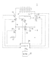
図例の給湯装置1において、2は熱交換器、3は燃焼検出センサ、4は熱交換器2を加熱するガスバーナなどの加熱器、6は図示しない水道管等に連通される入水路、8は台所、洗面所、シャワー等の端末栓5に連通される出湯路、10は入水路6と出湯路8との間で熱交換器2をバイパスするためのバイパス路、12はバイパス路10に設けられてバイパス水量を調整する流量調整弁、14は流量調整弁12の弁体(図示省略)を駆動するステッピングモータ、15はバイパス路10を流れる流量を検出する流量センサ、16は入水温度Tcを検出する入水温度センサ、18は熱交換器2で加熱された湯の出湯温度Thを検出する出湯温度センサ、20は熱交換器2で加熱された湯とバイパス路10を通過した水とが混合された後の給湯温度Tmを検出する給湯温度センサ、21は熱交換器2への入水量Qhを検出する入水量センサ、22は熱交換器2への通水量が最大加熱能力を越えた場合に湯水の吐出水量を制御する缶体側制御弁、23は加熱器4の加熱量を調節する比例弁、24は給湯動作に関連して前記各構成要素を制御するコントローラ、26は目標給湯温度Tsを設定する操作部である。
【0012】
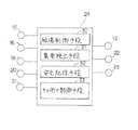
次に、コントローラ24について図2を参照して説明する。コントローラ24は、各種センサ15、16等の検出情報に基づいて、流量調整弁12、缶体側制御弁22、比例弁23等を制御したりするものであり、特に給湯制御手段30、異常検出手段31、安全処理手段32、及びその他の制御手段33とを有している。給湯制御手段30は通常の給湯動作の際に各動作部を制御する手段であり、入水量センサ21で検出する入水量Qhに基づいて給湯要求の有無を認識し、給湯動作時に下記フィードフォワード制御、フィードバック制御を行う。フィードフォワード制御は、熱交換器1での目標焚き上げ温度KTsを低温腐食域や沸騰域から外れる適正範囲となるように設定温度Tsに所要の一定値β(例えば25℃)を加算して算出して、この目標焚き上げ温度KTsに出湯温度センサ18で検出する出湯温度Thを一致させるように、加熱器4のガス量Gを(KTs−Tc)・QHにより算出して設定するとともに、目標分配比率BpFFを(KTs−Tc)/(Ts−Tc)=β/(Ts−Tc)により算出し、この目標分配比率BpFFに基づいてステッピングモータ14のステップ数と湯水分配比率との関係に基づいて目標ステップ数(目標値)SFFを算出するものである。また、フィードバック制御は、入水温度Tc、熱交換器2からの出湯温度Th、および湯水混合後の実際の給湯温度Tmに基づいて、実際の湯水の分配比率BpAを算出し、この実際分配比率BpAと前記目標分配比率BpFFとの偏差量△Bp(=BpA−BpFF)を所定のサンプリング周期△tごとに求め、この偏差量△Bpに基づいて補正分配比率BpFBを算出するものである。そして、これらフィードフォワード制御、フィードバック制御あるいはフィードフォワード+フィードバック制御を制御状態において適宜利用して最適な制御を行っている。
【0013】
異常検出手段31は、異常の発生の有無、その内容を検出する手段である。
【0014】
安全処理手段32は、異常が発生した場合の安全動作を処理する手段である。特に、安全処理手段32は利用者が意図しないときに高温の湯が出湯するのを防止するように考慮されている。その他の制御手段33は、上述以外の制御動作を行っている手段であり、各種センサ15、16等の検出動作を制御したり、操作部26とのデータの伝送制御を行ったりしている。
【0015】
次に、本発明の安全動作について図3のフローチャートを参照して説明する。まず、異常検出手段31が異常の有無を検出して安全処理手段32が安全動作が必要か否かを判断する(ステップS1)。その判断としては燃焼動作を行ったにもかかわらず燃焼が検出されない場合、残火異常が検出された場合、給湯動作を行ったにもかかわらず設定温度より高い高温出湯となってしまったり、あるいは設定温度よりも低い低温出湯となってしまった場合等、種々の異常動作をした場合である。ステップS1において、安全動作の必要がなければ通常の制御動作を実行継続する(ステップS2)。
【0016】
ステップS1において安全動作が必要であれば次に異常原因が所望の温度よりも高い温度の湯が出湯される高温出湯異常による安全動作か否かを判断する(ステップS3)。高温出湯異常でなければ缶体制御弁22及びバイパス路の流量調整弁12を全開(あるいは初期位置リセット)を行う(ステップS4)。高温出湯異常であれば缶体側制御弁22及びバイパス路の流量調整弁12を全閉とする(ステップS5)。ステップS4のように弁12、22の開動作を行うのは、双方の弁12、22を全閉としてしまえば燃焼を必要としない水の供給もできなくなってしまうため、できるだけ弁は開けておく方が望ましい。また、この場合には全開等で多量の水を流してゆるい湯水としている。その一方で、高温出湯異常の場合には、一旦給湯動作停止後も端末栓5までの出湯路8には高温の湯が満たされているため、利用者が不用意に端末栓5を開けても高温の湯が出湯されるのを防ぐ方が利用者に対してより利用し易くなる。そして、その際バイパス路の流量調整弁12及び缶体側制御弁22の双方を完全に全閉にしてしまえば、他に端末栓5を開けても上流側が完全に密閉されているため端末栓5からは出湯路8内の高温の湯が流れ出ない。仮に微少の湯が漏れ出たとしても少量であるため心配はない。また、別途端末栓5の付近に開閉用の電磁弁を設ける必要もなく実現できる。
【0017】
次に、他の実施例について説明する。上記実施例では高温出湯検出による安全動作のときに、缶体側制御弁22及びバイパス路の流量調整弁12を全閉にするようにしたているが、更に残火異常を検出した場合にも、図2のステップS5のように缶体側制御弁22及びバイパス路の流量調整弁12の双方を全閉するようにする。残火がある場合には残火によって出湯路8内の湯が更に加熱され高目の温度となっている。このとき利用者が不用意に端末栓5を開けても所望の温度より高い温度の湯が出湯されることはない。ここで残火の異常検出は、例えばコントローラ24から燃焼指令が出ていないにもかかわらず燃焼検出センサ3が燃焼を検出することにより行うことができる。
【0018】
【発明の効果】
以上説明したように、本発明では高温出湯異常あるいは残火検出した場合には、缶体側制御弁22及びバイパス路の流量調整弁12を完全に全閉してしまうため、仮に端末栓5を開けた場合でも利用者の所望の温度より高い温度の湯が出湯されず安心である効果がある。また、そのような場合以外の安全動作の際には開いているため、温水の供給はでき利用し易く便利である。
【図面の簡単な説明】
【図1】給湯装置の構成の説明図である。
【図2】コントローラの説明図である。
【図3】本発明の動作を示すフローチャートである。
【符号の説明】
1 給湯装置
2 熱交換器
3 燃焼検出センサ(残火検出手段)
4 加熱器
6 入水路
8 出湯路
10 バイパス路
12 流量調整弁
22 缶体側制御弁
24 コントローラ
26 操作部
30 給湯制御手段
31 異常検出手段
32 安全処理手段[0001]
BACKGROUND OF THE INVENTION
The present invention relates to a hot water supply apparatus, and more particularly to a hot water supply apparatus that prevents high-temperature hot water supply during safe operation.
[0002]
[Prior art]
Conventionally, as this type of hot water supply device, a water inlet and a hot water outlet are connected to a heater, a can body side control valve is provided on the hot water outlet, and a bypass path is provided between the water inlet and the hot water outlet. There is a configuration in which a short circuit is provided and a flow rate adjusting valve is provided in this bypass path. When the hot water is discharged, the gas burner is ignited and water is supplied to the heating side together with the bypass passage, and the hot water heated by the heater and the water flowing through the bypass passage are mixed to discharge desired hot water.
[0003]
Further, when an abnormality occurs in such a hot water supply apparatus, combustion is stopped and the can side control valve and the bypass flow rate adjustment valve are fully opened or set to a predetermined initial position. This is because even when the stoppage is abnormal, when the faucet is opened, a large amount of water is allowed to flow so that low-temperature hot water can be supplied.
[0004]
[Problem to be Solved by the Invention]
Although there are conventional hot water supply devices, the following problems may occur. When hot water supply abnormality is detected during hot water supply operation and hot water supply operation is stopped by safe operation, hot water is in the hot water supply path to the faucet, and the valve was not opened as in the past. When the faucet is opened, the hot water remaining in the tap is first drained, and then loose hot water is supplied. The user inadvertently opens the faucet even during safe operation. If this happens, hot water will be discharged.
[0005]
In addition, in a hot water supply device, the water flow switch is stuck at the ON position and it is difficult to move, or in the case of using a flow sensor, noise similar to the pulse signal from the flow sensor jumps into the control device or is controlled. When the microcomputer (CPU) in the device partially runs away, it is mistakenly recognized that there is a flow rate that is higher than the minimum operating flow rate (MOQ) even though there is no actual water flow. It is called afterfire.)
[0006]
Even in the case of a safe operation due to the afterfire, hot water is contained in the hot water path leading to the faucet, and there is a problem similar to that described above.
[0007]
Therefore, the present invention has been made in view of the above-described problems, and prevents the hot water from being discharged even when the user inadvertently opens the faucet even though it is in safe operation. An object is to provide a hot water supply apparatus.
[0008]
[Means for Solving the Problems]
To achieve the above object, the present invention includes a heat exchanger, a water inlet and a hot water outlet connected to the heat exchanger, a bypass path that bypasses the heat exchanger and allows the water inlet and the hot water path to communicate with each other, In a water heater having a flow rate adjusting valve for adjusting a bypass flow rate provided in the bypass passage, and a can body side control valve provided in the hot water passage, an abnormality detecting means for detecting an abnormality of the water heater, and the abnormality detecting means A safe processing means for determining whether or not a safe operation is necessary based on detection of a normal operation and if a safe operation is not necessary, execute a normal control operation. If the abnormality is not abnormally high temperature hot water, the can body side control valve and the flow rate adjustment valve are fully opened, and if the abnormality detecting means detects high temperature hot water abnormality, the flow rate adjustment valve and the can body side control valve are fully closed. Safe processing means to It is characterized in that Bei was.
[0009]
According to the first aspect of the present invention, if the hot water discharge abnormality (or afterfire detection) is detected, the can side control valve and the flow rate adjustment valve of the bypass passage are completely closed. Even in the case of hot water, it is safe because hot water is not discharged.
[0010]
DETAILED DESCRIPTION OF THE INVENTION
The details of the present invention will be described below based on the embodiment shown in FIGS. 1 and 2 are schematic configuration diagrams of the hot water supply apparatus of the present invention, and FIG. 3 is a flowchart for explaining the operation.
[0011]
In the hot
[0012]
Next, the
[0013]
The abnormality detection means 31 is a means for detecting whether or not an abnormality has occurred and its contents.
[0014]
The safety processing means 32 is a means for processing a safe operation when an abnormality occurs. In particular, the safety processing means 32 is considered to prevent hot water from coming out when the user does not intend. The other control means 33 is a means for performing control operations other than those described above, and controls the detection operations of the
[0015]
Next, the safe operation of the present invention will be described with reference to the flowchart of FIG. First, the abnormality detection means 31 detects the presence / absence of an abnormality, and the safety processing means 32 determines whether a safe operation is necessary (step S1). As the judgment, if combustion is not detected even though the combustion operation is performed, if an after-fire abnormality is detected, the hot water discharge is higher than the set temperature despite the hot water supply operation, or This is a case where various abnormal operations are performed, for example, when the temperature of the hot water is lower than the set temperature. In step S1, if there is no need for safe operation, normal control operation is continued (step S2).
[0016]
If a safe operation is necessary in step S1, it is next determined whether or not the cause of the abnormality is a safe operation due to a high-temperature hot water abnormality in which hot water having a temperature higher than a desired temperature is discharged (step S3). If it is not abnormal, the can body control
[0017]
Next, another embodiment will be described. In the above embodiment, the can body
[0018]
【The invention's effect】
As described above, in the present invention, when the high temperature hot water abnormality or afterfire is detected, the can body
[Brief description of the drawings]
FIG. 1 is an explanatory diagram of a configuration of a hot water supply apparatus.
FIG. 2 is an explanatory diagram of a controller.
FIG. 3 is a flowchart showing the operation of the present invention.
[Explanation of symbols]
1 Hot-
DESCRIPTION OF
Claims (1)
Priority Applications (1)
| Application Number | Priority Date | Filing Date | Title |
|---|---|---|---|
| JP24914196A JP3674014B2 (en) | 1996-08-30 | 1996-08-30 | Water heater |
Applications Claiming Priority (1)
| Application Number | Priority Date | Filing Date | Title |
|---|---|---|---|
| JP24914196A JP3674014B2 (en) | 1996-08-30 | 1996-08-30 | Water heater |
Publications (2)
| Publication Number | Publication Date |
|---|---|
| JPH1073315A JPH1073315A (en) | 1998-03-17 |
| JP3674014B2 true JP3674014B2 (en) | 2005-07-20 |
Family
ID=17188541
Family Applications (1)
| Application Number | Title | Priority Date | Filing Date |
|---|---|---|---|
| JP24914196A Expired - Fee Related JP3674014B2 (en) | 1996-08-30 | 1996-08-30 | Water heater |
Country Status (1)
| Country | Link |
|---|---|
| JP (1) | JP3674014B2 (en) |
Families Citing this family (2)
| Publication number | Priority date | Publication date | Assignee | Title |
|---|---|---|---|---|
| JP6079403B2 (en) * | 2013-04-18 | 2017-02-15 | 株式会社ノーリツ | Hot water supply apparatus and method for controlling hot water supply apparatus |
| JP6143642B2 (en) * | 2013-10-28 | 2017-06-07 | リンナイ株式会社 | Heat source machine |
-
1996
- 1996-08-30 JP JP24914196A patent/JP3674014B2/en not_active Expired - Fee Related
Also Published As
| Publication number | Publication date |
|---|---|
| JPH1073315A (en) | 1998-03-17 |
Similar Documents
| Publication | Publication Date | Title |
|---|---|---|
| JP3674014B2 (en) | Water heater | |
| JP3855328B2 (en) | Water heater | |
| JP3811998B2 (en) | Water heater | |
| JP3800667B2 (en) | Bath equipment | |
| JPH0426840Y2 (en) | ||
| JP3681532B2 (en) | Water heater | |
| JPH08247547A (en) | Hot water-supply device | |
| JPH1089770A (en) | Gas hot-water supplier | |
| JP3862811B2 (en) | One can two water bath hot water heater | |
| JPH10185322A (en) | Hot water supply apparatus | |
| JP2867758B2 (en) | Operation control method of bath kettle with water heater | |
| JP2624309B2 (en) | Hot water supply control method in automatic bath equipment with water heater | |
| JP3767012B2 (en) | Water heater | |
| JP3584454B2 (en) | Bath kettle with natural circulation water heater | |
| JP2508569B2 (en) | Water heater | |
| JP3859837B2 (en) | Combustion device | |
| JP3776985B2 (en) | Combustion equipment | |
| JP3271427B2 (en) | Water heater drain plug leak detector | |
| JPH0791742A (en) | Hot water feeding device | |
| JP2522130B2 (en) | How to determine the use of other plugs for a water heater with an automatic bath drop function | |
| JP2861521B2 (en) | Operation control method of bath kettle with water heater | |
| JPH0587358A (en) | Different faucet usage decision making method of hot water supply heater equipped with automatic hot water bath tub filling function | |
| JP2946862B2 (en) | Operation control method of bath kettle with water heater | |
| JPH02213645A (en) | Instantaneous hot water boiler | |
| JPH06249504A (en) | Hot water supply device |
Legal Events
| Date | Code | Title | Description |
|---|---|---|---|
| A977 | Report on retrieval |
Free format text: JAPANESE INTERMEDIATE CODE: A971007 Effective date: 20040903 |
|
| A131 | Notification of reasons for refusal |
Free format text: JAPANESE INTERMEDIATE CODE: A131 Effective date: 20041008 |
|
| A521 | Request for written amendment filed |
Free format text: JAPANESE INTERMEDIATE CODE: A523 Effective date: 20041105 |
|
| A131 | Notification of reasons for refusal |
Free format text: JAPANESE INTERMEDIATE CODE: A131 Effective date: 20050105 |
|
| A521 | Request for written amendment filed |
Free format text: JAPANESE INTERMEDIATE CODE: A523 Effective date: 20050203 |
|
| TRDD | Decision of grant or rejection written | ||
| A01 | Written decision to grant a patent or to grant a registration (utility model) |
Free format text: JAPANESE INTERMEDIATE CODE: A01 Effective date: 20050404 |
|
| A61 | First payment of annual fees (during grant procedure) |
Free format text: JAPANESE INTERMEDIATE CODE: A61 Effective date: 20050417 |
|
| R150 | Certificate of patent or registration of utility model |
Free format text: JAPANESE INTERMEDIATE CODE: R150 |
|
| FPAY | Renewal fee payment (event date is renewal date of database) |
Free format text: PAYMENT UNTIL: 20090513 Year of fee payment: 4 |
|
| FPAY | Renewal fee payment (event date is renewal date of database) |
Free format text: PAYMENT UNTIL: 20100513 Year of fee payment: 5 |
|
| FPAY | Renewal fee payment (event date is renewal date of database) |
Free format text: PAYMENT UNTIL: 20110513 Year of fee payment: 6 |
|
| FPAY | Renewal fee payment (event date is renewal date of database) |
Free format text: PAYMENT UNTIL: 20110513 Year of fee payment: 6 |
|
| FPAY | Renewal fee payment (event date is renewal date of database) |
Free format text: PAYMENT UNTIL: 20120513 Year of fee payment: 7 |
|
| LAPS | Cancellation because of no payment of annual fees |