JP3673987B2 - Tilt sensor - Google Patents
Tilt sensor Download PDFInfo
- Publication number
- JP3673987B2 JP3673987B2 JP35204498A JP35204498A JP3673987B2 JP 3673987 B2 JP3673987 B2 JP 3673987B2 JP 35204498 A JP35204498 A JP 35204498A JP 35204498 A JP35204498 A JP 35204498A JP 3673987 B2 JP3673987 B2 JP 3673987B2
- Authority
- JP
- Japan
- Prior art keywords
- movement
- state
- predetermined angle
- rotation
- predetermined
- Prior art date
- Legal status (The legal status is an assumption and is not a legal conclusion. Google has not performed a legal analysis and makes no representation as to the accuracy of the status listed.)
- Expired - Fee Related
Links
Images


Description
【0001】
【産業上の利用分野】
本発明は、車両の傾倒状態を検知する傾倒センサに関する。
【0002】
【従来の技術】
一般に、傾倒センサは、二輪自動車が転倒したり、四輪自動車が横転したことを検知して、エンジンを非常停止させるなどの種々の安全対策をとるために用いられている。
【0003】
従来、この種の傾倒センサとしては、車両の傾倒状態に応じて回動するバランス錘が所定以上に回動したときにリードスイッチが働いて車両の所定以上の傾倒状態を検知するようにしたものが存在する。そして、そのバランス錘は、車両走行時の振動による瞬間的な回動によって誤検知されることがないように、オイルダンパ機能をもたせるべく、比較的粘性の高いオイル中に浸されている。
【0004】
【発明が解決しようとする課題】
解決しようとする問題点は、従来の傾倒センサでは、ケースをオイル封入の密閉構造にしなければならず、部品点数、工数が多くなり、製造に時間がかかることである。また、オイルダンパー機能をもたせているために、使用環境温度によって傾倒状態の検知の応答時間がオイル粘度によって変化するものになっていることである。
【0005】
また、車両が所定以上に傾倒したときに、そのときのバランス錘の回動状態に応じてリードスイッチがオン状態になるようにするための調整が困難で、製品ごとにおける傾倒角度に応じた検知精度にばらつきを生ずる傾向があることである。
【0006】
【課題を解決するための手段】
本発明による傾倒センサは、何らダンパー機能をもたせないようにして、車両の傾倒状態の検知を、複雑な調整をすることなく応答性良くなすことができるようにするべく、円の中心に回転軸を有し、その円の中心を通る垂線に対して対称となるように上側部分に所定の開き角度をもって切欠部が形成され、着磁されたムーブメントの所定の角度以上の回動状態を所定の感度をもって精度良く検知することができるように、ムーブメントが所定の角度以上に回動して、ムーブメントの上方の前記垂線上の位置に設けられたホール素子がムーブメントのS極に対向したときにスイッチオンとなることによって、その所定の角度以上の回動が検知されるようにしたうえで、前記切欠部側の両端部分に微小な開き角度をもってN極がそれぞれ形成されるパターンをもってムーブメントを着磁するようにしている。
【0007】
そして、特に本発明では、例えば二輪自動車が傾倒したのちにもとの正常な状態に起き上がったような場合にも燃料カットやエンジン点火系統の電源しゃ断などの安全対策を継続しで行わせるようにするべく、ホール素子がムーブメントの所定の角度以上の回動状態を検知してスイッチオン状態となったときに傾倒状態の検知信号を出力するようにした検知回路内に、傾倒状態の検知信号の出力を保持する保持回路を設けるようにしている。
【0008】
【実施例】
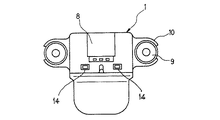
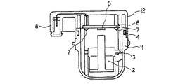
本発明による傾倒センサにあっては、図1および図2に示すように、ケース1内に、着磁された振子式のムーブメント2が回動軸3に回動自在になるように軸支されている。
【0009】
そのケース1は、ムーブメント2が取り付けられている下ケース11の上部分を上ケース12にシール用のOリング4を介して嵌め込み、その嵌め込み部分を複数箇所でフック係合することによって、防水構造となるように形成されている。図中、14はフック係合部分を示している。
【0010】
上ケース12の内部には、ムーブメント2の所定の角度以上の回動状態をホールIC5が検知して、それがスイッチオン状態となったときに検知信号を出力するようにした検知回路が実装された回路基板6が取り付けられている。図中、7はその取付用のネジを示している。
【0011】
そして、その上ケース12には、図3に示すように、回路基板6からの電源Vcc、アースGNDおよび検知出力OUTの各端子が外部に引き出されるソケット部8が一体的に形成されている。
【0012】
また、その上ケース12には、それを振動吸収用のゴムブッシュ9を介して車体側に取り付ける取付座10が設けられている。
【0013】
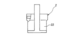
ムーブメント2には、図4および図5に示すように、円の中心に横方向の回動軸3が設けられている。そして、ムーブメント2の上部には円の中心を通る垂線となる回動の基準位置Oに対して対称となるように所定の開き角度α(例えば70°)をもった切欠部21が設けられ、その下部には基準位置Oが垂直方向にくるようにバランスをとるための重錘部22が設けられている。
【0014】
回路基板6に取り付けられているホールIC5は、ムーブメント2の基準位置O上に配されており、ムーブメント2が回動してそのS極が対向したときにスイッチオン状態になるようになっている。
【0015】
しかして、ムーブメント2の上部に切欠部21が設けられ、その下部に重錘部22が設けられているので、その重量配分が回動軸3の上方に比してその下方が充分重くなり、ムーブメント2を回動させるには大きなモーメントを必要とするものになって、車両走行時の振動によってはそのムーブメント2が回動しにくくなる。
【0016】
そして、ムーブメント2の上部には、その回動の基準位置Oが中央にくるように比較的大きな開き角度αをもって切欠部21が設けられているので、車両走行時の振動によってそのムーブメント2がその開き角度αの範囲内で揺動してもホールIC5が応動することがない。したがって、車両走行時の振動によって誤検知されるようなことがなく、車両が所定の角度以上に傾倒したときにのみホールIC5がスイッチオン状態になる。
【0017】
また、そのムーブメント2は、図4および図6に示すように、基準位置Oに対して対称となるように、図示の極性をもって異ピッチ多極となるように着磁されている。すなわち、切欠部21側の両端部分には微小な開き角β(例えば8°)をもってN極部が、またその下部には基準位置Oを中心とした微小な開き角γ
(例えば10°)をもってN極部がそれぞれ形成され、その各N極間にはそれぞれ所定の開き角δ(例えば132°)をもってS極部形成されている。
【0018】
しかして、このような異ピッチ多極構造をとることによって、N極部とS極部との境における磁束の変化を急峻にすることができ、ムーブメント2が所定の角度以上に回動してS極部がホールIC5に対向したときにスイッチオン状態になるときの位置決めを高精度に設定することができるようになる。
【0019】
図7は、ホールIC5のスイッチング状態に応じて車両の傾倒状態を検知するための検知回路の一例を示している。
【0020】
ここでは、ホールIC5がムーブメント2の所定の角度以上の回動状態を検知してスイッチオン状態となったときにハイレベルの検知信号を出力するような回路を構成したうえで、その検知回路内にコンデンサC1,C2および抵抗R4からなる時定数回路を設けて、その時定数によって決まる時間内でのホールIC5の瞬間的なスイッチオンには応答しないようにしている。
【0021】
すなわち、ホールIC5がスイッチオフ状態にある正常時には、コンデンサC1,C2が充電状態にあり、出力トランジスタQ4がオン状態になって出力端OUTの電圧はローレベルになっている。そして、車両が傾倒してホールIC5がスイッチオン状態になると、コンデンサC1,C2の放電回路が形成され、所定の時間後に出力トランジスタQ4がオフ状態になって出力端OUTの電圧がハイレベルに切り換わる。
【0022】
したがって、車両の走行振動によってムーブメント2が瞬間的に所定の角度以上に回動したときに、傾倒状態の誤検知がなされないようになる。
【0023】
なお、その際、ムーブメント2の回動が大きく、コンデンサC1,C2および抵抗R4の時定数によって設定される時間以上にわたってS極部分がホールIC5に対向してしまうと傾倒状態の誤検知がなされてしまうことになるので、図4および図6に示すように、中間にN極部分(無着磁部分であってもよい)を設けることによって磁極分割し、それにより設定時間以上にわたってS極部分がホールIC5に対向することがないようにしている。
【0024】
また、その検知回路には、制御用トランジスタQ2のコレクタに定電流を供給する定電流回路が設けられており、バッテリ電源(Vcc)の電圧が定格の仕様変更や充電状態、温度環境などによって変化しても傾倒状態検知のタイミングが変動することがないようしている。
【0025】
ここでは定電流回路として、ツエナダイオードZDを設けることによってバッテリ電源(Vcc)電源の定電圧化を図り、制御用トランジスタQ2のターンオンに際して抵抗R7を通して常に定電流によるコレクタ電流が供給されるようにしている。
【0026】
すなわち、このツエナダイオードZDおよび抵抗R7による定電流回路を設けない場合には、バッテリ電源(Vcc)の電圧が変動するとそれに応じて制御用トランジスタQ2コレクタ電流が変化してそのスイッチングのタイミングが変わってしまい、コンデンザC1,C2および抵抗R4によって決定される傾倒状態検知のタイミングが変動してしまうことになる。
【0027】
このような検知回路にあって、特に本発明では、その検知回路内に、抵抗R5,R6、コンデンサC3およびトランジスタQ1からなる傾倒状態検知の保持回路13を設けるようにしている。
【0028】
その傾倒状態検知の保持回路13において、車両の傾倒状態が検知されて出力トランジスタQ4がオフ状になって出力端OUTの電圧がハイレベルになると、トランジスタQ1がオン状態となり、それにより出力トランジスタQ4がオフ状態に保持される。
【0029】
その保持状態は、車両のイグニッションスイッチを切ってバッテリ電源(Vcc)をしゃ断することによって解除される。
【0030】
したがって、例えば二輪自動車が傾倒したのちにもとの正常な状態に起き上がったような場合にも、運転者の意思によって車両のイグニッションスイッチが切られるまで、燃料カットなどの安全対策が継続して行われることになる。
【0031】
【発明の効果】
以上、本発明にあっては、円の中心に回転軸を有し、その円の中心を通る垂線に対して対称となるように上側部分に所定の開き角度をもって切欠部が形成され、着磁されたムーブメントが所定の角度以上に回動して、ムーブメントの上方の前記垂線上の位置に設けられたホール素子がムーブメントのS極に対向したときにスイッチオンとなることによって、その所定の角度以上の回動が検知されるようにしたうえで、切欠部側の両端部分に微小な開き角度をもってN極がそれぞれ形成されるパターンをもってムーブメントを着磁するようにしているので、切欠部における両端部分の磁束密度の変化が急峻になって、車両が所定の角度以上に傾倒した状態を所定の感度をもって精度良く検知することができるようになる。そして、ホール素子がムーブメントの所定の角度以上の回動状態を検知したときに傾倒状態の検知信号を出力するようにした検知回路内に、傾倒状態の検知信号の出力を保持する保持回路を設けるようにしているので、例えば二輪自動車が傾倒したのちにもとの正常な状態に起き上がったような場合にも、運転者の意思によってその自己保持状態がリセットされるまで、燃料カットなどの安全対策を継続して行わせることができるという利点を有している。
【図面の簡単な説明】
【図1】本発明による傾倒センサの一実施例を示す正面図である。
【図2】同実施例における傾倒センサの側断面図である。
【図3】同実施例における傾倒センサのソケット端子部分の下面図である。
【図4】同実施例における傾倒センサのムーブメントを示す正面図である。
【図5】そのムーブメントの側面図である。
【図6】そのムーブメントにおける着磁パターンを示す展開図である。
【図7】車両の傾倒状態を検知するための検知回路を示す電気回路図である。
【符号の説明】
1 ケース
11 下ケース
12 上ケース
2 ムーブメント
3 軸
4 Oリング
5 ホールIC
6 回路基板
13 保持回路[0001]
[Industrial application fields]
The present invention relates to a tilt sensor that detects a tilt state of a vehicle.
[0002]
[Prior art]
In general, the tilt sensor is used to take various safety measures such as detecting that the two-wheeled vehicle has fallen or the four-wheeled vehicle has been rolled over and stopping the engine in an emergency.
[0003]
Conventionally, as this kind of tilt sensor, when the balance weight that rotates according to the tilting state of the vehicle rotates more than a predetermined value, the reed switch works to detect the tilting state of the vehicle exceeding the predetermined value. Exists. The balance weight is immersed in oil having a relatively high viscosity so as to have an oil damper function so as not to be erroneously detected due to momentary rotation caused by vibration during vehicle travel.
[0004]
[Problems to be solved by the invention]
The problem to be solved is that in the conventional tilt sensor, the case has to be sealed with oil, which increases the number of parts and man-hours, and takes time to manufacture. In addition, since the oil damper function is provided, the response time for detecting the tilted state changes depending on the oil viscosity due to the use environment temperature.
[0005]
Also, when the vehicle tilts more than a predetermined level, it is difficult to adjust the reed switch to turn on according to the rotation state of the balance weight at that time, and detection according to the tilt angle for each product There is a tendency for the accuracy to vary.
[0006]
[Means for Solving the Problems]
The tilt sensor according to the present invention does not have any damper function, so that the tilt state of the vehicle can be detected with good responsiveness without complicated adjustments. And a notch portion is formed in the upper portion with a predetermined opening angle so as to be symmetric with respect to a perpendicular passing through the center of the circle, and the rotation state of the magnetized movement at a predetermined angle or more is predetermined. A switch when the movement is rotated more than a predetermined angle so that the Hall element provided at the position on the perpendicular above the movement faces the S pole of the movement so that it can be detected with high sensitivity and accuracy. by on-and such Rukoto, in terms of its predetermined angle further rotation is to be detected, the cut portion with a small opening angle to both end portions N pole is respectively formed of So that magnetizing the movement with that pattern.
[0007]
In particular, in the present invention, for example, even when the motorcycle is tilted and then comes up to a normal state, safety measures such as fuel cut and engine ignition system power cut-off are continuously performed. Therefore, the detection signal of the tilted state is output in the detection circuit that outputs the detection signal of the tilted state when the Hall element detects the rotation state of the movement more than a predetermined angle and is switched on. A holding circuit for holding the output is provided.
[0008]
【Example】
In the tilt sensor according to the present invention, as shown in FIGS. 1 and 2, a magnetized
[0009]
The case 1 has a waterproof structure by fitting the upper portion of the lower case 11 to which the
[0010]
A detection circuit is mounted in the
[0011]
Further, as shown in FIG. 3, the
[0012]
Further, the
[0013]
As shown in FIGS. 4 and 5, the
[0014]
The
[0015]
Therefore, since the
[0016]
The upper portion of the
[0017]
Further, as shown in FIGS. 4 and 6, the
N pole portions are respectively formed (for example, 10 °), and S pole portions are formed between the N poles with a predetermined opening angle δ (for example, 132 °).
[0018]
Thus, by adopting such a different pitch multipolar structure, the change of the magnetic flux at the boundary between the N pole part and the S pole part can be made steep, and the
[0019]
FIG. 7 shows an example of a detection circuit for detecting the tilted state of the vehicle according to the switching state of the Hall IC 5.
[0020]
Here, the Hall IC 5 is configured to output a high-level detection signal when a movement state of the
[0021]
That is, at the normal time when the
[0022]
Therefore, when the
[0023]
At this time, if the
[0024]
In addition, the detection circuit is provided with a constant current circuit that supplies a constant current to the collector of the control transistor Q2, and the voltage of the battery power supply (Vcc) changes depending on the rated specification change, the charging state, the temperature environment, and the like. Even so, the timing of detecting the tilted state does not fluctuate.
[0025]
Here, as a constant current circuit, a Zener diode ZD is provided to make the battery power supply (Vcc) power supply constant so that the collector current is always supplied through the resistor R7 when the control transistor Q2 is turned on. Yes.
[0026]
That is, when the constant current circuit by the Zener diode ZD and the resistor R7 is not provided, if the voltage of the battery power supply (Vcc) varies, the control transistor Q2 collector current changes accordingly and the switching timing changes. Therefore, the tilt detection timing determined by the condensers C1 and C2 and the resistor R4 varies.
[0027]
In such a detection circuit, in the present invention, in particular, a tilt state
[0028]
In the tilt state
[0029]
The holding state is released by turning off the ignition switch of the vehicle and cutting off the battery power supply (Vcc).
[0030]
Therefore, for example, even if the motorcycle is tilted and then comes up to a normal state, safety measures such as fuel cut will continue until the vehicle's ignition switch is turned off. It will be.
[0031]
【The invention's effect】
As described above, according to the present invention, a notch is formed in the upper portion with a predetermined opening angle so as to be symmetric with respect to a perpendicular passing through the center of the circle and having a rotation axis at the center of the circle, and movement is rotated beyond a predetermined angle that is, the Hall element provided at a position on the vertical line of the upper movement is by switching on and such Rukoto when facing the S pole of the movement, of the predetermined Since the rotation more than the angle is detected, the movement is magnetized with a pattern in which N poles are formed at both end portions on the notch portion side with a minute opening angle. The change in the magnetic flux density at both end portions becomes steep, so that the state in which the vehicle is tilted more than a predetermined angle can be detected with a predetermined sensitivity with high accuracy. A holding circuit for holding the output of the tilt detection signal is provided in the detection circuit that outputs a tilt detection signal when the Hall element detects a rotation state of a predetermined angle or more of the movement. For example, even if the motorcycle gets up to its normal state after being tilted, safety measures such as fuel cut will be taken until the self-holding state is reset by the driver's intention. Has the advantage of being able to continue.
[Brief description of the drawings]
FIG. 1 is a front view showing an embodiment of a tilt sensor according to the present invention.
FIG. 2 is a side sectional view of a tilt sensor in the same embodiment.
FIG. 3 is a bottom view of the socket terminal portion of the tilt sensor in the same embodiment.
FIG. 4 is a front view showing the movement of the tilt sensor in the same embodiment.
FIG. 5 is a side view of the movement.
FIG. 6 is a development view showing a magnetization pattern in the movement.
FIG. 7 is an electric circuit diagram showing a detection circuit for detecting the tilted state of the vehicle.
[Explanation of symbols]
1 Case 11
6
Claims (1)
Priority Applications (1)
| Application Number | Priority Date | Filing Date | Title |
|---|---|---|---|
| JP35204498A JP3673987B2 (en) | 1998-11-05 | 1998-11-05 | Tilt sensor |
Applications Claiming Priority (1)
| Application Number | Priority Date | Filing Date | Title |
|---|---|---|---|
| JP35204498A JP3673987B2 (en) | 1998-11-05 | 1998-11-05 | Tilt sensor |
Publications (2)
| Publication Number | Publication Date |
|---|---|
| JP2000146578A JP2000146578A (en) | 2000-05-26 |
| JP3673987B2 true JP3673987B2 (en) | 2005-07-20 |
Family
ID=18421403
Family Applications (1)
| Application Number | Title | Priority Date | Filing Date |
|---|---|---|---|
| JP35204498A Expired - Fee Related JP3673987B2 (en) | 1998-11-05 | 1998-11-05 | Tilt sensor |
Country Status (1)
| Country | Link |
|---|---|
| JP (1) | JP3673987B2 (en) |
Families Citing this family (2)
| Publication number | Priority date | Publication date | Assignee | Title |
|---|---|---|---|---|
| JP6450223B2 (en) * | 2015-03-06 | 2019-01-09 | エイブリック株式会社 | Sensor device and inspection method thereof |
| CN117232480B (en) * | 2023-11-14 | 2024-02-06 | 济南市槐荫区市政工程服务中心 | Slope measuring device and method for municipal road foundation pit support |
-
1998
- 1998-11-05 JP JP35204498A patent/JP3673987B2/en not_active Expired - Fee Related
Also Published As
| Publication number | Publication date |
|---|---|
| JP2000146578A (en) | 2000-05-26 |
Similar Documents
| Publication | Publication Date | Title |
|---|---|---|
| US6527077B2 (en) | Body incline sensor for a motorcycle | |
| US7383637B2 (en) | Inclination sensor and method of attaching the same | |
| US20170151992A1 (en) | Device for enhanced safety in using a side stand for parking of two wheeled vehicle | |
| JP3673987B2 (en) | Tilt sensor | |
| AU731528B2 (en) | Measuring device for the contactless detection of a rotational angle | |
| JP3673988B2 (en) | Tilt sensor | |
| JP3590927B2 (en) | Tilt sensor | |
| JP3590925B2 (en) | Tilt sensor | |
| JP3975389B2 (en) | Tilt detection device | |
| JP3590926B2 (en) | Tilt sensor | |
| JP2000149736A (en) | Inclination sensor | |
| JP3590930B2 (en) | Tilt sensor | |
| JP3590929B2 (en) | Tilt sensor | |
| JP2000146581A (en) | Tilt sensor | |
| JP2000146579A (en) | Tilt sensor | |
| WO2006038297A1 (en) | Inclination sensor | |
| JP2913906B2 (en) | Tilt detector | |
| JP3584012B2 (en) | Tilt sensor for boarding means | |
| JP2005049321A (en) | Inclination sensor | |
| JPH0674708A (en) | Throttle opening detector | |
| KR19980058685A (en) | Turn indicator | |
| JPH0390407A (en) | Detecting device for air pressure in tire | |
| JPH0328007A (en) | Tire air pressure detecting device | |
| KR0142743B1 (en) | Yawing sensor of motor | |
| JPH0446808A (en) | Pneumatic pressure detecting device for tire |
Legal Events
| Date | Code | Title | Description |
|---|---|---|---|
| A977 | Report on retrieval |
Free format text: JAPANESE INTERMEDIATE CODE: A971007 Effective date: 20040209 |
|
| A131 | Notification of reasons for refusal |
Free format text: JAPANESE INTERMEDIATE CODE: A131 Effective date: 20040323 |
|
| A521 | Written amendment |
Free format text: JAPANESE INTERMEDIATE CODE: A523 Effective date: 20040519 |
|
| A131 | Notification of reasons for refusal |
Free format text: JAPANESE INTERMEDIATE CODE: A131 Effective date: 20040727 |
|
| A521 | Written amendment |
Free format text: JAPANESE INTERMEDIATE CODE: A523 Effective date: 20040908 |
|
| A02 | Decision of refusal |
Free format text: JAPANESE INTERMEDIATE CODE: A02 Effective date: 20041124 |
|
| A521 | Written amendment |
Free format text: JAPANESE INTERMEDIATE CODE: A523 Effective date: 20041209 |
|
| A911 | Transfer of reconsideration by examiner before appeal (zenchi) |
Free format text: JAPANESE INTERMEDIATE CODE: A911 Effective date: 20050128 |
|
| TRDD | Decision of grant or rejection written | ||
| A01 | Written decision to grant a patent or to grant a registration (utility model) |
Free format text: JAPANESE INTERMEDIATE CODE: A01 Effective date: 20050405 |
|
| A61 | First payment of annual fees (during grant procedure) |
Free format text: JAPANESE INTERMEDIATE CODE: A61 Effective date: 20050415 |
|
| R150 | Certificate of patent or registration of utility model |
Free format text: JAPANESE INTERMEDIATE CODE: R150 |
|
| FPAY | Renewal fee payment (event date is renewal date of database) |
Free format text: PAYMENT UNTIL: 20090513 Year of fee payment: 4 |
|
| FPAY | Renewal fee payment (event date is renewal date of database) |
Free format text: PAYMENT UNTIL: 20090513 Year of fee payment: 4 |
|
| FPAY | Renewal fee payment (event date is renewal date of database) |
Free format text: PAYMENT UNTIL: 20100513 Year of fee payment: 5 |
|
| FPAY | Renewal fee payment (event date is renewal date of database) |
Free format text: PAYMENT UNTIL: 20110513 Year of fee payment: 6 |
|
| FPAY | Renewal fee payment (event date is renewal date of database) |
Free format text: PAYMENT UNTIL: 20120513 Year of fee payment: 7 |
|
| FPAY | Renewal fee payment (event date is renewal date of database) |
Free format text: PAYMENT UNTIL: 20120513 Year of fee payment: 7 |
|
| FPAY | Renewal fee payment (event date is renewal date of database) |
Free format text: PAYMENT UNTIL: 20130513 Year of fee payment: 8 |
|
| LAPS | Cancellation because of no payment of annual fees |