JP3673898B2 - Composite anchor bolt and its construction method - Google Patents
Composite anchor bolt and its construction method Download PDFInfo
- Publication number
- JP3673898B2 JP3673898B2 JP2001291739A JP2001291739A JP3673898B2 JP 3673898 B2 JP3673898 B2 JP 3673898B2 JP 2001291739 A JP2001291739 A JP 2001291739A JP 2001291739 A JP2001291739 A JP 2001291739A JP 3673898 B2 JP3673898 B2 JP 3673898B2
- Authority
- JP
- Japan
- Prior art keywords
- anchor bolt
- anchor
- composite
- connecting member
- reinforcing bar
- Prior art date
- Legal status (The legal status is an assumption and is not a legal conclusion. Google has not performed a legal analysis and makes no representation as to the accuracy of the status listed.)
- Expired - Fee Related
Links
Images


Landscapes
- Foundations (AREA)
- Joining Of Building Structures In Genera (AREA)
- Reinforcement Elements For Buildings (AREA)
Description
【0001】
【発明の属する技術分野】
本発明は、コンクリート床面、壁面、天井面等にあと施工アンカーを施工する際に使用するアンカーボルト及びその施工方法に関するものである。
【0002】
【従来の技術】
従来、あと施工アンカーは接着系アンカーと本体打込みアンカーに区別され、各々その種類は多数に及ぶ。図10は、従来の接着系アンカーのあと施工アンカーの施工例を示す。図10(1)のようにコンクリート躯体9に、接着剤を封入したカプセル15を埋め込む穿孔をあけ、図10(2)のように専用ブラシ25で穿孔を清掃し、図10(3)のようにカプセル15を挿入後、図10(4)のようにアンカーボルト18を攪拌しながら挿入し、図10(5)のように接着剤を硬化させてコンクリート、アンカーボルトを固着させることにより、アンカーボルトの取付けが完了する。また、接着材の種類によっては、アンカーボルトを攪拌する必要がなく、ハンマーでアンカーボルトを打撃して接着剤を混合し、アンカーボルトを固着させる方法もある。本発明では、このハンマー打ち込み式の接着剤の入ったカプセル(例えばMUアンカー)を使用するか或いは、注入ガンで接着材を穿孔に注入する方法を採用する。
【0003】
【発明が解決しようとする課題】
従来のあと施工アンカーボルトの施工における最大の問題点は、コンクリートの中に鉄筋が存在し、アンカーボルト用の穿孔がこの鉄筋に遭遇すると、あと施工アンカーボルトが施工できないことである(但し、あと施工アンカーの長さが小さい場合を除く)。あと施工アンカーボルトの強度を確保するためには、コンクリート中に所定の埋込み長さが必要であるのだが、通常コンクリート表面より約30〜60mmの深さに鉄筋が存在するため、アンカーボルト用の穿孔がこの鉄筋に遭遇するとアンカーボルトの正規の長さをとることができない。これを図によって説明すると、図11において、Dはアンカーボルト18が鉄筋12に遭遇しない場合であり、アンカーボルト18の正規のアンカー長Lをとることができる。これに対しEは穿孔10が鉄筋12に遭遇して正規のアンカー長Lをとれない場合を示す。なお、図中26は、コンクリート躯体9の表面である。また、Fはかぶり代である。
【0004】
従来この問題を解決する方法は、図12(1)のように、鉄筋に当った場所より離れて鉄筋12をさけるように30°程斜めにアンカーボルト18を打込むしかなかった。アンカーを打った後、図12(2)のように台直しといってアンカーボルトをコンクリート面で垂直になるように力を加えて曲げることを行っていた。ところが、上記斜めにアンカーを打つとコンクリート面での位置がずれやすい、施工が難しい、台直しによりアンカーボルトに局所的な残留応用を与え、強度上問題がある等の色々な問題が生ずる。このような理由で、かなりの熟練工でないと良い仕事ができず、施工に当たりはずれが生じていた。なお、台直しはボルト径がM16の太さまでは容易であるが、M20以上では人力では困難であり、現状では大口径のアンカーボルトはやむおえずダイヤモンドカッターで鉄筋を切断する等の処置を行って、アンカーを施工していた。
【0005】
本発明は、コンクリート床面、壁面、天井面等にあと施工アンカーを施工する際に、コンクリート中の鉄筋とアンカーボルト用の穿孔が鉄筋に遭遇した場合に、施工したいアンカーの位置を変更しないでその位置に正確に施工可能で、かつ所定の強度を有するアンカーボルト及びその施工方法を提供することを目的とする。
【0006】
【課題を解決するための手段】
本発明は、コンクリート躯体にあと施工するアンカーボルトにおいて、コンクリ−ト躯体外に突出施工される取付け用ねじ部と、コンクリート躯体内に埋め込み施工されるアンカーボルト部とを一体的に設け、前記埋め込み施工されるアンカーボルト部のアンカー長をコンクリート鉄筋かぶり代より長く形成するとともに、施工したいアンカー位置に配置される前記取り付け用ねじ部の軸芯と埋め込み施工されるアンカーボルト部の軸芯と偏芯させて鉄筋との遭遇を回避可能に形成してなることを特徴とする複合アンカーボルトである。
【0007】
また、本発明は、施工したいアンカー位置で鉄筋に遭遇した穿孔に施工する、アンカー長がかぶり代より短い第1のアンカーボルトと、アンカー長がかぶり代より長くかつコンクリート躯体外に出る取付け用ねじ部を持たない第2のアンカーボルトと、前記第1のアンカーボルトと前記第2のアンカーボルトを一体的に連結する連結部材を有することを特徴とする複合アンカーボルトである。
【0008】
また、本発明は、第1のアンカーボルトの埋め込み深さを調節可能とし、第2のアンカーボルトと連結部材の一端部を一体的に形成し、前記連結部材の他端部に前記第1のアンカーボルトのねじ部と螺合する雌ねじ部を形成したことを特徴とする複合アンカーボルトである。ここで、適宜第1のアンカーボルトの全面にわたりねじ部を形成するのがよい。
【0009】
第1のアンカーボルトと第2のアンカーボルトの夫々の軸芯間の距離が約30〜150mmであることが好適である。
連結部材の横断面は矩形、或いは上部が平坦側の半円形、或いは円形であることが好適である。
【0010】
また、本発明は、第1のアンカーボルト、第2のアンカーボルト及び連結部材が一体的に形成されていることを特徴とする複合アンカーボルトである。ここで、適宜外周の全面にねじ部を形成してもよい。
【0011】
また、本発明は、コンクリート躯体の外に出ている取付け用ねじ部を中心として、所定の距離をおいて、複数本のアンカーボルト部を一体的に配置したことを特徴とする複合アンカーボルトである。
【0012】
また、本発明は、第1のアンカーボルト及び第2のアンカーボルトのコンクリート埋設部が、丸棒状又は表面に凹凸のある鉄筋形状であることを特徴とする複合アンカーボルトである。
【0013】
そして、本発明の複合アンカーボルトの施工方法は、コンクリート躯体にアンカーボルトをあと施工する際に、鉄筋に遭遇した、正規の施工したいアンカーの位置と鉄筋に遭遇しないアンカーの位置に夫々第1及び第2の穿孔を設けるとともに、前記第1及び第2の穿孔間に溝を設け、前記第1及び第2の穿孔と前記溝に、2本のアンカーボルトを連結部材で一体に形成した複合アンカーボルトを施工することを特徴とするものである。
【0014】
そして、本発明は、コンクリート躯体にアンカーボルトをあと施工する際に、あと施工アンカー用の第1の穿孔が鉄筋に遭遇した場合に、前記第1の穿孔を覗いて、遭遇の状況が、(A)穿孔が上下方向の鉄筋に当たったのか、或いは、(B)穿孔が左右方向の鉄筋当たったのか、(C)穿孔が上下左右方向の鉄筋に当たったのかを判別し、(A)の場合には鉄筋の左右か左右斜め方向のうちの何れか一方向を選択し、(B)の場合には鉄筋の上下か上下斜め方向のうちの何れか一方向を選択し、(C)の場合には、鉄筋の上下斜め方向のうちの何れか一方向を選択し、前記選択された方向に、前記第1の穿孔から所定の距離をおいた位置に、かぶり代より深い深さに第2の穿孔をあける工程と、前記第1の穿孔と第2の穿孔の間に複合アンカーの連結部が嵌合する溝を形成する工程と、アンカー長がかぶり代より短い第1のアンカーボルトと、アンカー長がかぶり代より長くかつコンクリート外に出る取付け用ねじ部を持たない第2のアンカーボルトと、前記第1のアンカーボルトと前記第2のアンカーボルトを連結する連結部材を有する複合アンカーボルトを夫々前記第1の穿孔、前記第2の穿孔及び前記溝に施工する工程を含むことを特徴とするものである。
【0015】
【作用】
通常、鉄筋は図1のように、碁盤の目のように配筋されているので、鉄筋の位置が分からない場合、一回目のあと施工アンカーの穿孔が鉄筋10に遭遇する位置の種類は、図1のA、B、C、の3通りある。Aは南北方向の鉄筋に穿孔が当った場合、Bは東西方向の鉄筋に穿孔が当った場合、Cは東西南北方向の鉄筋クロス部に当った場合である。図中黒丸は、アンカー用穿孔が鉄筋に遭遇した位置を示す。なお、一般的な構造物の場合、鉄筋の直径は約10〜22mm、鉄筋のピッチは約100〜250mmである。
【0016】
本発明者は、一回目のあと施工アンカーの穿孔を覗けば、A、B、Cいずれのパターンか判別がつき、Aパターンでは左右か左右斜め方向、Bパターンでは上下か上下斜め方向、Cパターンでは上下斜め方向か左右斜め方向には、すぐ近くに鉄筋がないことが予想できることを見出した。そこで、これらの方向のうちの一つを選択して、A、B、C、からある距離X(約30〜150mm)をおいた位置に穿削孔をあけるようルールづければ、必要なアンカー長の穿孔をほぼ100%の確率で施工できることを見出した。
図中白丸は、選択した穿孔の位置を示す。本発明者は、この距離Xに着目して、以下に説明する複合アンカーボルト及びその施工方法を発明した。
【0017】
【発明の実施の形態】
以下本発明の一実施例を説明する。図2(1)は本発明の複合アンカーボルトの一実施例を示す平面図、図2(2)は図2(1)のA矢視図、図2(3)は図2(1)のB矢視図、図2(4)は図2(1)のC〜C断面図である。これらの図において、1は本発明の複合アンカーボルトである。2は鉄筋に遭遇した穿孔に施工する、アンカー長がかぶり代より短い第1のアンカーボルトであり、アンカーボルト2を固定するための外周面に溝が設けられている接着部3、及び連結部材5の雌ねじ部6と螺合するボルト部4から成る。
【0018】
7はアンカー長がかぶり代より長くかつコンクリート外に出る取付け用ねじ部を持たない第2のアンカーボルトであり、外周部にアンカーボルト7を固定するための溝が設けられている接着部8から成り、先端は連結部材5に固着されている。9はコンクリート躯体である。
【0019】
この複合アンカーボルトにおいて、連結部材5の上面より上の部分はコンクリート躯体9の表面より外にでる。即ち、大気中或いは水中にでる。一方、連結部材5の上面から下の部分は、コンクリート躯体9の内部に埋め込まれ、接着部3、8において、接着剤によりコンクリート躯体9と一体的に固定される。コンクリート躯体9との接着力の強さは、主に接着部8のアンカーボルトの表面積×単位面積当たりの接着強度によって決まる。つまり接着部8の長さが長いほど、接着力は大きくなる。補助的には、第1アンカーボルトの接着部3にも接着力は発生するが計算上は除外することとする。この接着力により、第1のアンカーボルト2のボルト部4に加わる引抜き力を求めることができる。また、ボルト部4に加わるせん断力は、ほとんどの場合、コンクリート躯体中に埋め込まれたアンカーボルトの断面積によって求めることができる。アンカーボルトの材質は適宜、SS400、ステンレス、アルミニウム、鋳鉄、SCS等が使用される。
【0020】
次に、この複合アンカーボルトの施工例について、図により説明する。図3(1)、(2)、(3)、(4)は順次施工工程を示す説明図である。
先ず、コンクリート躯体9にアンカーボルトをあと施工する際に、鉄筋の位置が分からない場合に、あと施工アンカーの第1の穿孔10が鉄筋12に遭遇した場合、前記第1の穿孔10を覗いて、遭遇の状況が、(A)穿孔が南北方向(上下方向)の鉄筋に当たったのか、或いは、(B)穿孔が東西方向(左右方向)の鉄筋に当たったのか、(C)穿孔が東西南北方向(上下左右方向)の鉄筋に当たったのかを判別し、(A)の場合には鉄筋の左右か左右斜め方向のうちの何れか一方向を選択し、(B)の場合には鉄筋の上下か上下斜め方向のうちの何れか一方向を選択し、(C)の場合には、鉄筋の上下斜め方向のうちの何れか一方向を選択する。そして。この選択した方向に、第1の穿孔10から所定の距離Xをおいた位置に、鉄筋12を超えた所定の深さに第2の穿孔11をあける。この際、第1の穿孔10を中心にして、半径Xの円弧を描き、この円弧上に、選択された方向に、次の穿孔11の位置をマーキングするのが便利である。図3(1)において、P点があと施工アンカーを打ちたい位置である。
【0021】
次に、図3(2)のように、第1の穿孔10と第2の穿孔11の間に、ダイヤモンドカッター刃をつけたディスクサンダーと振動ドリルで連結部材5が嵌合する溝14を形成する。そして、第1の穿孔10、第2の穿孔11及び溝14を清掃後、第1の穿孔10及び第2の穿孔11に、前述の接着剤カプセル15を挿入し、本発明の複合アンカーボルト1をハンマーで叩き込む。そして、コンクリート躯体9と連結部材5の隙間をコーキングし、接着剤の硬化を待つて施工が完了する。
【0022】
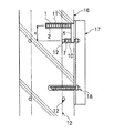
図4は、本発明の複合アンカーボルト1を壁面に施工した例を示し、16はコンクリート壁面、17はサポートアングルを示す。18は通常のアンカーボルトである。
【0023】
図5は、本発明の複合アンカーボルト1を床面に施工した例を示し、19はコンクリート床面、20はサポート部を示す。
図6(1)、(2)において、第1のアンカーボルト2はその外周の全面にボルト部4が形成された構造になっている。そして、第2のアンカーボルト7と連結部材5の一端部は一体的に形成されており、連結部材5の他端部に第1のアンカーボルト2のボルト部4と螺合する雌ねじ部6が形成されている。このような構成にしたので、第1のアンカーボルト2と第2のアンカーボルト7との相対位置を、施工に応じて調節することが可能であり便利である。第1のアンカーボルト2と連結材5を一体的に形成する場合は、第1アンカーボルト2の長さを鉄筋までの深さに応じて切断して、長さを調整する。
【0024】
本発明の複合アンカーボルトの形状は、以上説明したものに限らず、例えば、第1のアンカーボルト、第2のアンカーボルト及び連結部材が一体的に形成されているものや、図7のように、外周の全面にねじ部21が形成されているもの、或いは、図8のように、コンクリート躯体の外に出ている取付け用ボルト部22を中心として、距離Xをおいて、2本のアンカーボルト23を一体的に配置したものを適宜使用してもよい。また、第1のアンカーボルト及び第2のアンカーボルトのコンクリート埋設部は、ねじ以外の形状例えば丸棒状或いは鉄筋形状等でもよい。
【0025】
以上、接着形のアンカーボルトを例について説明したが、本発明の複合アンカーボルトは、打ち込み式のあと施工アンカーボルトにも適用できる。図9は、このような例を示したものである。図9において、24は打ち込み式(くさび形)アンカーボルトである。
【0026】
【発明の効果】
以上説明したように、本発明によれば、コンクリート床面、壁面、天井面等に、あと施工アンカーを施工する際に、コンクリート中の鉄筋とアンカーボルト用の穿孔が遭遇した場合に、施工したいアンカー位置を変更しないで、その位置に正確に施工でき、かつアンカー強度を十分に保つことができる。また、従来のように斜め打ちする必要がないので、熟練工でなくとも簡便容易に施工でき、品質も向上することができる。
【図面の簡単な説明】
【図1】本発明における施工の際に穿孔の位置を選択する方法の説明図である。
【図2】(1)は本発明の複合アンカーボルトの実施例を示す平面図、(2)は(1)のA矢視図、(3)は(1)のB矢視図、(4)は(1)のC〜C断面図である。
【図3】本発明の複合アンカーボルトの施工工程を示す説明図である。
【図4】図4は本発明の複合アンカーボルトを壁面に施工した例を示す一部断面図である。
【図5】本発明の複合アンカーボルトを床面に施工した例を示す一部断面図である。
【図6】本発明の複合アンカーボルトの他の実施例を示す平面図である。
【図7】本発明の複合アンカーボルトの他の実施例を示す平面図である。
【図8】本発明の複合アンカーボルトの他の実施例を示す平面図である。
【図9】本発明の複合アンカーボルトの他の実施例を示す平面図である。
【図10】従来の接着系アンカーの施工例を示す説明図である。
【図11】従来のあと施工アンカーの施工上の問題点の説明図である。
【図12】穿孔が鉄筋に遭遇した場合の従来のあと施工アンカーの施工例の説明図である。
【符号の説明】
1………複合アンカーボルト、2………第1のアンカーボルト、3………第1アンカーボルト接着部、4………取付け用ねじ部、5………連結部材、6………雌ねじ部、7………第2のアンカーボルト、8………第2アンカーボルト接着部、9………コンクリート躯体、10………第1の穿孔、11………第2の穿孔、12………鉄筋、13………振動ドリル、14………溝、15………接着材カプセル、16………コンクリート壁面、17………サポートアングル、18………通常のアンカーボルト、19………コンクリート床面、20………サポート部、21………ねじ部、22………取付け用ボルト部、23………アンカーボルト、24………打ち込み式アンカーボルト、25………専用ブラシ、26………コンクリート躯体の表面。[0001]
BACKGROUND OF THE INVENTION
The present invention relates to an anchor bolt used when a post-construction anchor is constructed on a concrete floor surface, a wall surface, a ceiling surface or the like, and a construction method thereof.
[0002]
[Prior art]
Conventionally, post-installed anchors are classified into adhesive anchors and main body driven anchors, each of which has many types. FIG. 10 shows a construction example of a post-construction anchor after a conventional adhesive anchor. As shown in FIG. 10 (1), the
[0003]
[Problems to be solved by the invention]
The biggest problem in conventional post-installed anchor bolt construction is that there is a reinforcing bar in the concrete, and if the anchor bolt drilling encounters this reinforcing bar, post-installed anchor bolt cannot be installed (however, Except when the anchor length is small). In order to ensure the strength of the anchor bolts after construction, a predetermined embedding length is required in the concrete. However, since the reinforcing bars exist at a depth of about 30 to 60 mm from the concrete surface, If a perforation encounters this rebar, the normal length of the anchor bolt cannot be taken. This will be described with reference to the drawings. In FIG. 11, D is a case where the
[0004]
Conventionally, as a method for solving this problem, as shown in FIG. 12 (1), the
[0005]
The present invention does not change the position of the anchor to be constructed when a reinforcing bar in the concrete and a drill for an anchor bolt encounter the reinforcing bar when constructing a post-installed anchor on a concrete floor surface, wall surface, ceiling surface, etc. An object of the present invention is to provide an anchor bolt capable of being accurately constructed at the position and having a predetermined strength, and a construction method thereof.
[0006]
[Means for Solving the Problems]
According to the present invention, in an anchor bolt to be subsequently applied to a concrete frame, a mounting screw part projecting out of the concrete frame and an anchor bolt part embedded in the concrete frame are integrally provided, and the embedded The anchor length of the anchor bolt part to be constructed is longer than the concrete rebar cover allowance, and the shaft core of the mounting screw part arranged at the anchor position to be constructed and the axis of the anchor bolt part to be embedded and eccentricity The composite anchor bolt is characterized in that it is formed so as to avoid encounter with a reinforcing bar .
[0007]
In addition, the present invention provides a first anchor bolt having an anchor length shorter than a cover allowance, and a mounting screw which is longer than the cover allowance and is installed outside the concrete frame, which is applied to a drilling which encounters a reinforcing bar at an anchor position to be applied. A composite anchor bolt comprising: a second anchor bolt having no portion; and a connecting member that integrally connects the first anchor bolt and the second anchor bolt.
[0008]
According to the present invention, the embedding depth of the first anchor bolt can be adjusted, the second anchor bolt and one end of the connecting member are integrally formed, and the other end of the connecting member is connected to the first anchor bolt. It is a composite anchor bolt characterized in that a female thread portion that is screwed with a thread portion of the anchor bolt is formed. Here, it is preferable to form a thread portion over the entire surface of the first anchor bolt as appropriate.
[0009]
It is preferable that the distance between the axial centers of the first anchor bolt and the second anchor bolt is about 30 to 150 mm.
It is preferable that the cross section of the connecting member is a rectangle, or a semicircular shape with a flat upper portion, or a circular shape.
[0010]
In addition, the present invention is a composite anchor bolt characterized in that the first anchor bolt, the second anchor bolt, and the connecting member are integrally formed. Here, you may form a thread part in the whole outer periphery suitably.
[0011]
Further, the present invention is a composite anchor bolt characterized in that a plurality of anchor bolt portions are integrally arranged at a predetermined distance around a mounting screw portion protruding outside the concrete frame. is there.
[0012]
Moreover, the present invention is a composite anchor bolt characterized in that the concrete embedded portions of the first anchor bolt and the second anchor bolt are in the shape of a round bar or a reinforced bar having an uneven surface .
[0013]
And the construction method of the composite anchor bolt of this invention is 1st and 2nd in the position of the anchor which does not encounter a rebar, and the position of the anchor which does not encounter a rebar, which encountered the rebar, respectively, when the anchor bolt was post-installed to the concrete frame A composite anchor in which a second perforation is provided, a groove is provided between the first and second perforations, and two anchor bolts are integrally formed by a connecting member in the first and second perforations and the groove. It is characterized by constructing bolts.
[0014]
And, when the first drilling for the post-construction anchor encounters a reinforcing bar when the anchor bolt is post-constructed on the concrete frame , the present invention looks into the first drilling and the situation of the encounter is ( Do a) drilling hits the vertical reinforcing bar, or, (B) or the perforation hit rebar in the horizontal direction, it is determined whether the (C) drilling hits the vertical and horizontal directions rebar, the (a) In the case, either one of the left and right or left and right diagonal directions of the reinforcing bar is selected. In the case of (B), either one of the vertical and diagonal directions of the reinforcing bar is selected, and (C) In this case, one of the upper and lower diagonal directions of the reinforcing bar is selected, and a depth greater than the covering margin is set at a position at a predetermined distance from the first perforation in the selected direction. Two perforations, and a composite annulus between the first and second perforations. A step of forming a groove into which the connecting portion of the first member is fitted, a first anchor bolt having an anchor length shorter than the cover allowance, and a second having an anchor length longer than the cover allowance and having no mounting screw portion that goes out of the concrete. And a composite anchor bolt having a connecting member for connecting the first anchor bolt and the second anchor bolt to the first drilling, the second drilling and the groove, respectively. It is characterized by this.
[0015]
[Action]
Normally, as shown in Fig. 1, the reinforcing bars are arranged like a grid, so if you do not know the position of the reinforcing bars, the type of position where the drilling of the construction anchor encounters the reinforcing
[0016]
When the present inventor looks at the drilling of the construction anchor after the first time, it is possible to determine whether the pattern is A, B, or C. In the A pattern, the pattern is left / right or left / right diagonally, in the B pattern, vertical / vertical diagonally, So, it was found that there is no rebar in the immediate vicinity in the diagonal direction. Therefore, if one of these directions is selected and a rule is made so that a drilling hole is made at a distance X (about 30 to 150 mm) from A, B, C, the necessary anchor It has been found that long perforations can be constructed with a probability of almost 100%.
White circles in the figure indicate the positions of the selected perforations. The inventor invented a composite anchor bolt and its construction method described below, paying attention to this distance X.
[0017]
DETAILED DESCRIPTION OF THE INVENTION
An embodiment of the present invention will be described below. 2 (1) is a plan view showing an embodiment of the composite anchor bolt of the present invention, FIG. 2 (2) is a view as viewed from an arrow A in FIG. 2 (1), and FIG. 2 (3) is FIG. 2 (1). B arrow figure and FIG. 2 (4) are CC sectional drawings of FIG. 2 (1). In these figures, 1 is the composite anchor bolt of the present invention. 2 is a first anchor bolt having an anchor length shorter than a cover allowance, which is applied to a perforation encountered with a reinforcing bar, an
[0018]
[0019]
In this composite anchor bolt, the part above the upper surface of the connecting
[0020]
Next, a construction example of this composite anchor bolt will be described with reference to the drawings. 3 (1), (2), (3) and (4) are explanatory views showing the construction process in sequence.
First, when post-installing anchor bolts on the
[0021]
Next, as shown in FIG. 3 (2), a
[0022]
FIG. 4 shows an example in which the
[0023]
FIG. 5 shows an example in which the
6 (1) and 6 (2), the
[0024]
The shape of the composite anchor bolt of the present invention is not limited to that described above. For example, the first anchor bolt, the second anchor bolt and the connecting member are integrally formed, as shown in FIG. Two anchors with a distance X centered on the mounting
[0025]
The adhesive anchor bolt has been described above as an example, but the composite anchor bolt of the present invention can also be applied to a post-installed anchor bolt. FIG. 9 shows such an example. In FIG. 9, 24 is a drive-in (wedge-shaped) anchor bolt.
[0026]
【The invention's effect】
As described above, according to the present invention, when post-construction anchors are constructed on a concrete floor surface, wall surface, ceiling surface, etc., when reinforcements in the concrete and drilling for anchor bolts are encountered, the construction is desired. Without changing the anchor position, construction can be performed accurately at that position, and the anchor strength can be sufficiently maintained. Moreover, since it is not necessary to strike diagonally as in the prior art, construction can be easily performed even if it is not a skilled worker, and the quality can be improved.
[Brief description of the drawings]
FIG. 1 is an explanatory diagram of a method for selecting a drilling position at the time of construction in the present invention.
2A is a plan view showing an embodiment of a composite anchor bolt of the present invention, FIG. 2B is a view taken along an arrow A in FIG. 1A, FIG. 3B is a view taken along an arrow B in FIG. ) Is a cross-sectional view taken along the line C-C in (1).
FIG. 3 is an explanatory view showing a construction process of the composite anchor bolt of the present invention.
FIG. 4 is a partial cross-sectional view showing an example in which the composite anchor bolt of the present invention is applied to a wall surface.
FIG. 5 is a partial cross-sectional view showing an example in which the composite anchor bolt of the present invention is applied to a floor surface.
FIG. 6 is a plan view showing another embodiment of the composite anchor bolt of the present invention.
FIG. 7 is a plan view showing another embodiment of the composite anchor bolt of the present invention.
FIG. 8 is a plan view showing another embodiment of the composite anchor bolt of the present invention.
FIG. 9 is a plan view showing another embodiment of the composite anchor bolt of the present invention.
FIG. 10 is an explanatory view showing a construction example of a conventional adhesive anchor.
FIG. 11 is an explanatory diagram of problems in construction of a conventional post-construction anchor.
FIG. 12 is an explanatory diagram of a construction example of a conventional post-construction anchor when a perforation encounters a reinforcing bar.
[Explanation of symbols]
DESCRIPTION OF
Claims (14)
Priority Applications (1)
| Application Number | Priority Date | Filing Date | Title |
|---|---|---|---|
| JP2001291739A JP3673898B2 (en) | 2001-09-25 | 2001-09-25 | Composite anchor bolt and its construction method |
Applications Claiming Priority (1)
| Application Number | Priority Date | Filing Date | Title |
|---|---|---|---|
| JP2001291739A JP3673898B2 (en) | 2001-09-25 | 2001-09-25 | Composite anchor bolt and its construction method |
Publications (2)
| Publication Number | Publication Date |
|---|---|
| JP2003096918A JP2003096918A (en) | 2003-04-03 |
| JP3673898B2 true JP3673898B2 (en) | 2005-07-20 |
Family
ID=19113833
Family Applications (1)
| Application Number | Title | Priority Date | Filing Date |
|---|---|---|---|
| JP2001291739A Expired - Fee Related JP3673898B2 (en) | 2001-09-25 | 2001-09-25 | Composite anchor bolt and its construction method |
Country Status (1)
| Country | Link |
|---|---|
| JP (1) | JP3673898B2 (en) |
Families Citing this family (6)
| Publication number | Priority date | Publication date | Assignee | Title |
|---|---|---|---|---|
| JP4697550B2 (en) * | 2004-06-30 | 2011-06-08 | スエヒロシステム株式会社 | Composite anchor bolt and its construction method |
| JP2009041312A (en) * | 2007-08-10 | 2009-02-26 | Keiyo Aaki Metal Kk | Method of erecting strut with anchor bolt |
| JP5866633B2 (en) * | 2011-04-19 | 2016-02-17 | 西武ポリマ化成株式会社 | Fixed structure of expansion joint for concrete structures |
| JP6395396B2 (en) * | 2014-02-18 | 2018-09-26 | 三菱重工業株式会社 | Device mounting device and device mounting method |
| JP7386669B2 (en) * | 2019-11-12 | 2023-11-27 | 東芝プラントシステム株式会社 | Base plate and base plate fixing method |
| KR102423545B1 (en) * | 2020-10-23 | 2022-07-20 | 경상국립대학교산학협력단 | Concrete surface tensile hardening method for joining external structures |
Family Cites Families (3)
| Publication number | Priority date | Publication date | Assignee | Title |
|---|---|---|---|---|
| JPS612550U (en) * | 1984-06-09 | 1986-01-09 | 株式会社明電舎 | Foundation bolts for equipment installation |
| JPH1089334A (en) * | 1996-09-11 | 1998-04-07 | Sho Bond Constr Co Ltd | Eccentric anchor bolt |
| JP2001107471A (en) * | 1999-08-03 | 2001-04-17 | Tsutsunaka Sheet Bosui Kk | Erecting structure and erecting method of fixing bolt on waterproofed surface |
-
2001
- 2001-09-25 JP JP2001291739A patent/JP3673898B2/en not_active Expired - Fee Related
Also Published As
| Publication number | Publication date |
|---|---|
| JP2003096918A (en) | 2003-04-03 |
Similar Documents
| Publication | Publication Date | Title |
|---|---|---|
| JP4902504B2 (en) | Cloth foundation reinforcement structure, construction method of cloth foundation reinforcement structure and reinforcement hardware | |
| KR101242476B1 (en) | Base construct method of building and base construct member of building | |
| JP3673898B2 (en) | Composite anchor bolt and its construction method | |
| JP4498348B2 (en) | Screwed steel pipe pile | |
| JP5150596B2 (en) | Anchor device and anchor construction method | |
| JP4723938B2 (en) | Construction method of foundation structure | |
| JP2017128860A (en) | Reinforcing construction method and reinforcement structure of concrete structure | |
| KR101228754B1 (en) | Method for retrofitting seismic capability of mansory partition wall | |
| JPH11140869A (en) | Screwed-in type steel pipe pile with wing | |
| JP3937382B2 (en) | Construction method of screwed steel pipe pile | |
| JP2814355B2 (en) | Pile embedding device and method of embedding pile for foundation | |
| JP2006233593A (en) | Reinforcing method of circumference of perforation section after construction of single arrangement foundation for low-rise housing | |
| JP2003055965A (en) | Soil cement columnar body with thin steel pipe present as core material and its construction method | |
| JP2002047650A (en) | Set anchor body and executing method therefor | |
| JP5963301B2 (en) | Assembled blade member for steel pipe pile, steel pipe pile, composite pile and method for manufacturing composite pile | |
| JP4224905B2 (en) | Threaded steel pipe pile and its construction method | |
| JP6004565B2 (en) | Banded blade member for steel pipe pile, steel pipe pile, composite pile, and composite pile manufacturing method | |
| JP4697550B2 (en) | Composite anchor bolt and its construction method | |
| JP3686593B2 (en) | Resin combined anchor device | |
| JP5378137B2 (en) | Reinforcement structure for existing fabric foundation and foundation | |
| JP5534593B2 (en) | Saddle, slope reinforcement method and slope reinforcement structure using this fence | |
| JP2010090573A (en) | Structure and method for anchoring reinforcement to reinforced concrete structure | |
| JP6647778B2 (en) | Post-installed anchor and its installation method | |
| JP4443992B2 (en) | Installation basic block of vending machine and its fixing method | |
| JP3694824B2 (en) | Threaded steel pipe pile and its construction method |
Legal Events
| Date | Code | Title | Description |
|---|---|---|---|
| A977 | Report on retrieval |
Free format text: JAPANESE INTERMEDIATE CODE: A971007 Effective date: 20041104 |
|
| A131 | Notification of reasons for refusal |
Free format text: JAPANESE INTERMEDIATE CODE: A131 Effective date: 20041118 |
|
| A521 | Written amendment |
Free format text: JAPANESE INTERMEDIATE CODE: A523 Effective date: 20050117 |
|
| TRDD | Decision of grant or rejection written | ||
| A01 | Written decision to grant a patent or to grant a registration (utility model) |
Free format text: JAPANESE INTERMEDIATE CODE: A01 Effective date: 20050408 |
|
| A61 | First payment of annual fees (during grant procedure) |
Free format text: JAPANESE INTERMEDIATE CODE: A61 Effective date: 20050411 |
|
| R150 | Certificate of patent or registration of utility model |
Free format text: JAPANESE INTERMEDIATE CODE: R150 |
|
| FPAY | Renewal fee payment (event date is renewal date of database) |
Free format text: PAYMENT UNTIL: 20080513 Year of fee payment: 3 |
|
| FPAY | Renewal fee payment (event date is renewal date of database) |
Free format text: PAYMENT UNTIL: 20090513 Year of fee payment: 4 |
|
| FPAY | Renewal fee payment (event date is renewal date of database) |
Free format text: PAYMENT UNTIL: 20090513 Year of fee payment: 4 |
|
| FPAY | Renewal fee payment (event date is renewal date of database) |
Free format text: PAYMENT UNTIL: 20140513 Year of fee payment: 9 |
|
| R250 | Receipt of annual fees |
Free format text: JAPANESE INTERMEDIATE CODE: R250 |
|
| R250 | Receipt of annual fees |
Free format text: JAPANESE INTERMEDIATE CODE: R250 |
|
| LAPS | Cancellation because of no payment of annual fees |