JP3672533B2 - SOFT MAGNETIC FILM, THIN FILM MAGNETIC HEAD USING THE SOFT MAGNETIC FILM, METHOD FOR PRODUCING THE SOFT MAGNETIC FILM, AND METHOD FOR MANUFACTURING THE THIN FILM MAGNETIC HEAD - Google Patents
SOFT MAGNETIC FILM, THIN FILM MAGNETIC HEAD USING THE SOFT MAGNETIC FILM, METHOD FOR PRODUCING THE SOFT MAGNETIC FILM, AND METHOD FOR MANUFACTURING THE THIN FILM MAGNETIC HEAD Download PDFInfo
- Publication number
- JP3672533B2 JP3672533B2 JP2002005914A JP2002005914A JP3672533B2 JP 3672533 B2 JP3672533 B2 JP 3672533B2 JP 2002005914 A JP2002005914 A JP 2002005914A JP 2002005914 A JP2002005914 A JP 2002005914A JP 3672533 B2 JP3672533 B2 JP 3672533B2
- Authority
- JP
- Japan
- Prior art keywords
- layer
- mass
- magnetic
- film
- alloy
- Prior art date
- Legal status (The legal status is an assumption and is not a legal conclusion. Google has not performed a legal analysis and makes no representation as to the accuracy of the status listed.)
- Expired - Fee Related
Links
Images


Description
【0001】
【発明の属する技術分野】
本発明は、例えば薄膜磁気ヘッドのコア材として使用される軟磁性膜に係り、前記軟磁性膜にFeCoαあるいはFeCoRh(元素αは貴金属)合金を使用することで飽和磁束密度Bsを2.0T以上にでき、且つ耐食性を向上させることが可能な軟磁性膜とこの軟磁性膜を用いた薄膜磁気ヘッド、ならびに前記軟磁性膜の製造方法と前記薄膜磁気ヘッドの製造方法に関する。
【0002】
【従来の技術】
例えば薄膜磁気ヘッドのコア層には、特に今後の高記録密度化に伴い、高い飽和磁束密度Bsを有する磁性材料を使用し、前記コア層のギャップ近傍に磁束を集中させて、記録密度を向上させる必要がある。
【0003】
前記磁性材料には従来からNiFe系合金がよく使用されている。前記NiFe系合金は、直流電流を用いた電気メッキ法によりメッキ形成され、1.8T程度の飽和磁束密度Bsを得ることが可能であった。
【0004】
【発明が解決しようとする課題】
しかしながら今後の高記録密度化に伴い、さらに高い飽和磁束密度Bsを満たす軟磁性膜を製造することが必要となり、NiFe系合金では十分にその要望に応えることができなかった。
【0005】
またNiFe系合金以外によく使用される軟磁性材料としてFeCo合金膜がある。前記FeCo合金膜は、Feの組成比を適正に調整することで、NiFe系合金膜よりも高い飽和磁束密度Bsが得られる一方、次のような問題点が発生した。
【0006】
薄膜磁気ヘッドや他の磁気素子の構成によっては、前記FeCo合金の上にNiFe系合金を重ねたり、あるいはメッキ形成された非磁性層(例えばギャップ層)の上下に前記FeCo合金を重ねる場合があるが、前記FeCo合金膜を電気メッキ法によりメッキ形成するときなどに、FeCo合金膜がイオン化して溶け出し腐食するといった問題が発生したのである。
【0007】
これは前記FeCo合金膜とNiFe系合金膜との間、あるいは前記FeCo合金膜と非磁性層間には大きな電位差(標準電極電位差)が発生するからであり、この電位差によりいわゆる電池効果が生じて溶け出すものと考えられる。
【0008】
またFeCo合金膜が単層で形成される場合も、薄膜磁気ヘッドや他の磁気素子の製造方法においては、耐食性が要求される。例えばスライダの研削工程や素子の洗浄工程に曝される場合でも腐食しないことが要求される。また薄膜磁気ヘッドの使用上の環境的な要因にも耐食性が要求される。
【0009】
従って薄膜磁気ヘッドのコア層などに使用される軟磁性膜には、高い飽和磁束密度Bsのみならず、優れた耐食性も必要であった。
【0010】
そこで本発明は上記従来の課題を解決するためのものであり、FeCo合金にPdやRhなどの貴金属の元素を添加することにより、飽和磁束密度Bsを2.0T以上にできると同時に耐食性にも優れた軟磁性膜とこの軟磁性膜を用いた薄膜磁気ヘッド、ならびに前記軟磁性膜の製造方法と薄膜磁気ヘッドの製造方法を提供することを目的としている。
【0036】
【課題を解決するための手段】
本発明における軟磁性膜の製造方法は、メッキ浴中のFeイオン濃度を1.2g/l以上で3.2g/l以下とし、Coイオン濃度を0.86g/l以上で1.6g/l以下とし、元素αイオン濃度を0.2mg/l以上で6mg/l以下とする電気メッキ法により、Feの組成比X(質量%)/Coの組成比Y(質量%)の比率が、2以上で5以下で、元素α(ただし元素αは、Pd)の組成比Zが、0.5質量%以上で18質量%以下であり、X+Y+Z=100質量%の関係を満たすFeXCoYαZ合金をメッキ形成することを特徴とするものである。この組成比を有する軟磁性膜であれば飽和磁束密度Bsを2.0T以上にできるとともに、元素αを含まないFeCo合金に比べて耐食性に優れた軟磁性膜を製造することが可能である。
【0037】
また本発明では、前記Feの組成比X(質量%)/Coの組成比Y(質量%)の比率が、2.6以上で4.3以下で、元素αの組成比Zが3質量%以上で9質量%以下であり、X+Y+Z=100質量%の関係を満たすFeXCoYαZ合金をメッキ形成することが好ましい。この組成比を有する軟磁性膜であれば飽和磁束密度Bsを2.2T以上にできるとともに元素αを含まないFeCo合金に比べて耐食性に優れた軟磁性膜を製造することが可能である。
【0039】
後述する実験結果によれば、上記のメッキ浴組成を有することで、確実にFeの組成比X(質量%)/Coの組成比Y(質量%)の比率が、2以上で5以下で、元素αの組成比Zが、0.5質量%以上で18質量%以下であり、X+Y+Z=100質量%の関係を満たすFeXCoYαZ合金、好ましくは、前記Feの組成比X(質量%)/Coの組成比Y(質量%)の比率が、2.6以上で4.3以下で、元素αの組成比Zが3質量%以上で9質量%以下であり、X+Y+Z=100質量%の関係を満たすFeXCoYαZ合金をメッキ形成することができる。
【0040】
また本発明では、メッキ浴中にβイオン(ただし元素βはNi、Crの一方あるいは両方)を添加し、前記FeXCoYαZ合金に0.5質量%以上で5質量%以下の組成比Vを有する元素βを含有させ、X+Y+Z+V=100質量%の関係を満たすFeXCoYαZβV合金をメッキ形成してもよい。
【0047】
上記のように本発明では、好ましくはFeCoα合金をパルス電流を用いた電気メッキ法によってメッキ形成する。パルス電流を用いた電気メッキ法では、例えば電流制御素子のON/OFFを繰返し、メッキ形成時に、電流を流す時間と、電流を流さない空白な時間を設ける。このように電流を流さない時間を設けることで、FeCoα合金膜を、少しずつメッキ形成し、従来のように直流電流を用いた場合に比べメッキ形成時における電流密度の分布の偏りを緩和することが可能になっている。パルス電流による電気メッキ法によれば直流電流による電気メッキ法に比べて軟磁性膜中に含まれるFe含有量の調整が容易になり、前記Fe含有量を膜中に多く取り込むことができる。
【0048】
また本発明では、FeCoα合金、FeCoαβ合金のメッキ浴中にサッカリンナトリウムを混入することが好ましい。サッカリンナトリウム(C6H4CONNaSO2)は応力緩和剤としての役割を有しており、したがって前記サッカリンナトリウムを混入することでFeCoα合金、FeCoαβ合金の膜応力を低減させることが可能である。
【0049】
また本発明では、前記メッキ浴中に、2−ブチン−1、4ジオールを混入することが好ましい。これによってメッキ形成されたFeCoα合金、FeCoαβ合金の結晶粒径の粗大化は抑制され、前記結晶粒径が小さくなることで結晶間に空隙が生じ難くなり、膜面の面粗れが抑制される。面粗れを抑制できることで保磁力Hcを小さくすることも可能になる。
【0050】
また本発明では、前記メッキ浴中に2−エチルヘキシル硫酸ナトリウムを混入することが好ましい。これによってメッキ浴中に生じる水素は、界面活性剤である2−エチルヘキシル硫酸ナトリウムによって除去され、前記水素がメッキ膜に付着することによる面粗れを抑制できる。
【0051】
また前記2−エチルヘキシル硫酸ナトリウムに代えて、ラウリル硫酸ナトリウムを用いても良いが、2−エチルヘキシル硫酸ナトリウムを用いた方が、メッキ浴中に混入したときの泡立ちが少なく、したがって前記2−エチルヘキシル硫酸ナトリウムをメッキ浴中に多く混入することができ、前記水素の除去をより適切に行うことが可能になる。
【0052】
また本発明は、磁性材料製の下部コア層と、記録媒体との対向面で前記下部コア層と磁気ギャップを介して対向する上部コア層と、両コア層に記録磁界を誘導するコイル層とを有する薄膜磁気ヘッドの製造方法において、
少なくとも一方のコア層を、上記に記載された製造方法による軟磁性膜でメッキ形成することを特徴とするものである。
【0053】
また本発明では、前記下部コア層上に記録媒体との対向面で下部磁極層を隆起形成し、前記下部磁極層を前記軟磁性膜でメッキ形成することが好ましい。
【0054】
また本発明は、下部コア層及び上部コア層と、前記下部コア層と上部コア層との間に位置し且つトラック幅方向の幅寸法が前記下部コア層及び上部コア層よりも短く規制された磁極部とを有し、
前記磁極部を、下部コア層と連続する下部磁極層、上部コア層と連続する上部磁極層、および前記下部磁極層と前記上部磁極層間に位置するギャップ層とで形成し、あるいは前記磁極部を、上部コア層と連続する上部磁極層、および前記上部磁極層と下部コア層との間に位置するギャップ層とで形成し、
このとき前記上部磁極層及び/または下部磁極層を、上記に記載された製造方法による軟磁性膜でメッキ形成することを特徴とするものである。
【0055】
また本発明では、前記上部磁極層を前記軟磁性膜でメッキ形成し、前記上部磁極層上に上部コア層を電気メッキ法によりNiFe系合金膜でメッキ形成することが好ましい。
【0056】
また本発明では、前記コア層を、少なくとも磁気ギャップに隣接する部分で2層以上の磁性層で形成し、あるいは前記磁極層を2層以上の磁性層で形成し、このとき前記磁性層のうち前記磁気ギャップに接する磁性層を、前記軟磁性膜によりメッキ形成することが好ましい。
【0057】
また本発明では、前記磁気ギャップ層に接する以外の他の磁性層を電気メッキ法によりNiFe系合金でメッキ形成することが好ましい。
【0058】
上記したように本発明における軟磁性膜としてのFeCoα合金、FeCoαβ合金を、電気メッキ法によりメッキ形成することで、Feの組成比X(質量%)/Coの組成比Y(質量%)の比率が、2以上で5以下で、元素α(ただし元素αは、Pd)の組成比Zが0.5質量%以上で18質量%以下となる、好ましくは、Feの組成比X(質量%)/Coの組成比Y(質量%)の比率が、2.6以上で4.3以下で、元素αの組成比Zが3質量%以上で9質量%以下となる、FeXCoYαZ合金及び、さらに元素βの組成比Vが0.5質量%以上で5質量%以下となるFeXCoYαZβV合金をメッキ形成することが可能である。
【0060】
そしてこのような軟磁性膜を薄膜磁気ヘッドのコア材として使用することで、飽和磁束密度Bsが高く高記録密度化を図ることができ、また元素αやRhを含まないFeCo合金を用いる場合に比べて耐食性にも優れた薄膜磁気ヘッドを歩留まり良く製造することが可能である。
【0061】
【発明の実施の形態】
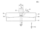
図1は、本発明の第1実施形態の薄膜磁気ヘッドの部分正面図、図2は図1に示す薄膜磁気ヘッドを2−2線から切断し矢印方向から見た縦断面図である。
【0062】
本発明における薄膜磁気ヘッドは、浮上式ヘッドを構成するセラミック材のスライダ11の側端面11aに形成されたものであり、MRヘッドh1と、書込み用のインダクティブヘッドh2とが積層された、MR/インダクティブ複合型薄膜磁気ヘッド(以下、単に薄膜磁気ヘッドという)となっている。
【0063】
MRヘッドh1は、磁気抵抗効果を利用してハードディスクなどの記録媒体からの洩れ磁界を検出し、記録信号を読み取るものである。
【0064】
図2に示すように、前記スライダ11のトレーリング側端面11a上にAl2O3膜12を介してNiFe等からなる磁性材料製の下部シールド層13が形成され、さらにその上に絶縁材料製の下部ギャップ層14が形成されている。
【0065】
前記下部ギャップ層14上には記録媒体との対向面からハイト方向(図示Y方向)に向けて、異方性磁気抵抗効果(AMR)素子、巨大磁気抵抗効果(GMR)素子あるいはトンネル型磁気抵抗効果(TMR)素子などの磁気抵抗効果素子10が形成され、さらに前記磁気抵抗効果素子10及び下部ギャップ層14上には絶縁材料製の上部ギャップ層15が形成されている。さらに前記上部ギャップ層15の上にNiFe等の磁性材料で形成された上部シールド層16が形成されている。MRヘッドh1は、前記下部シールド層13から上部シールド層16までの積層膜で構成されている。
【0066】
次に図1及び2に示す実施形態では、前記上部シールド層16がインダクティブヘッドh2の下部コア層としても兼用されており、前記下部コア層16上には、Gd決め層17が形成され、記録媒体との対向面から前記Gd決め層17の先端部までの長さ寸法でギャップデプス(Gd)が規制される。前記Gd決め層17は例えば有機絶縁材料で形成される。
【0067】
また前記下部コア層16の上面16aは図1に示すように、磁極部18の基端からトラック幅方向(図示X方向)に離れるにしたがって下面方向に傾く傾斜面で形成されており、これによりサイドフリンジングの発生を抑制することが可能である。
【0068】
また図2に示すように、記録媒体との対向面から前記Gd決め層17上にかけて磁極部18が形成されている。
【0069】
前記磁極部18は下から下部磁極層19、非磁性のギャップ層20、及び上部磁極層21が積層されている。
【0070】
前記下部磁極層19は、下部コア層16上に直接メッキ形成されている。また前記下部磁極層19の上に形成されたギャップ層20は、メッキ形成可能な非磁性金属材料で形成されていることが好ましい。具体的には、NiP、NiPd、NiW、NiMo、Au、Pt、Rh、Pd、Ru、Crのうち1種または2種以上から選択されたものであることが好ましい。
【0071】
なお本発明における具体的な実施形態として前記ギャップ層20にはNiPが使用される。NiPで前記ギャップ層20を形成することで前記ギャップ層20を適切に非磁性状態にできるからである。
【0072】
さらに前記ギャップ層20の上にメッキ形成された上部磁極層21は、その上に形成される上部コア層22と磁気的に接続される。
【0073】
上記のようにギャップ層20がメッキ形成可能な非磁性金属材料で形成されると、下部磁極層19、ギャップ層20及び上部磁極層21を連続メッキ形成することが可能である。
【0074】
なお前記磁極部18は、ギャップ層20及び上部磁極層21の2層で構成されていてもよい。
【0075】
図1に示すように、前記磁極部18はトラック幅方向(図示X方向)における幅寸法がトラック幅Twで形成されている。
【0076】
図1及び図2に示すように、前記磁極部18のトラック幅方向(図示X方向)の両側及びハイト方向後方(図示Y方向)には例えば無機絶縁材料からなる絶縁層23が形成されている。前記絶縁層23の上面は前記磁極部18の上面と同一平面とされる。
【0077】
図2に示すように、前記絶縁層23上にはコイル層24が螺旋状にパターン形成されている。また前記コイル層24上は有機絶縁材料製の絶縁層25によって覆われている。なお前記コイル層24は絶縁層を挟んで2層以上積層された構成であっても良い。
【0078】
図2に示すように、磁極部18上から絶縁層25上にかけて上部コア層22が例えばフレームメッキ法によりパターン形成されている。図1に示すように、前記上部コア層22の先端部22aは、記録媒体との対向面側でのトラック幅方向における幅寸法がT1で形成され、かかる幅寸法T1はトラック幅Twよりも大きく形成されている。
【0079】
また図2に示すように、前記上部コア層22の基端部22bは、下部コア層16上に形成された磁性材料製の接続層(バックギャップ層)26上に直接接続されている。
【0080】
本発明では、前記上部磁極層21及び/または下部磁極層19が以下の組成比を有する軟磁性膜で形成されている。
(1)組成式がFeXCoYαZ(ただし元素αは、Pd)で示され、Feの組成比X(質量%)/Coの組成比Y(質量%)の比率は、2以上で5以下で、元素αの組成比Zは、0.5質量%以上で18質量%以下であり、X+Y+Z=100質量%の関係を満たし、メッキ形成されることを特徴とする軟磁性膜。
【0081】
後述する実験結果により上記の組成比を有するFeCoα合金であると飽和磁束密度Bsを2.0T以上にできることが確認された。このように本発明ではNiFe系合金よりも高い飽和磁束密度Bsを得ることが可能である。
【0082】
Fe及びCoは磁性を担う元素である。Fe、Coの組成比を適切な値にすることによって高い飽和磁束密度を得ることが可能になる。後述する実験によれば、前記Feの組成比X(質量%)/Coの組成比Y(質量%)の比率を2以上で5以下にすると、前記Bsを2.0T以上にできることが確認された。
【0083】
次に前記元素αは特に耐食性を高めるために添加される元素であり、前記元素αが少なすぎると効果的に耐食性を向上させることはできず、多すぎても磁性を担うFe、Co量の減少によって飽和磁束密度Bsの低下を招く。本発明では前記元素αの組成比Zを0.5質量%以上で18質量%以下とすることで、飽和磁束密度Bsを2.0T以上にできると同時にCoとFeのみからなる軟磁性膜よりも効果的に耐食性を向上させることができる。また前記元素αのうち、Pd、Ptのいずれか一種または2種以上を添加すると、より効果的に耐食性を向上させることが可能である。特に前記元素αはPdであることが好ましい。
【0084】
また上記組成比を有するFeCoα合金であると、結晶が緻密に形成されることで膜面の面粗れを少なくでき、耐食性を向上させることができるとともに、保磁力Hcを小さくすることができる。具体的には前記保磁力を2000(A/m)以下にすることが可能である。
【0085】
またFeCoα合金が上記組成範囲内であると、15(μΩ・cm)以上の比抵抗を得ることができる。また膜応力を400MPa以下にすることができる。さらに異方性磁界Hkに関しては、従来から軟磁性材料として一般的に使用されているNiFe系合金と同程度の異方性磁界Hkを得ることができる。
【0086】
また本発明では、前記Feの組成比X(質量%)/Coの組成比Y(質量%)の比率は、2.6以上で4.3以下で、元素αの組成比Zは3質量%以上で9質量%以下であり、X+Y+Z=100質量%の関係を満たすことが好ましい。これにより飽和磁束密度Bsを2.2T以上にすることができると共に元素αを含まないFeCo合金に比べて効果的に耐食性の向上を図ることが可能である。
【0087】
また本発明では、上記FeCoα合金に元素β(ただし元素βはNi、Crの一方あるいは両方)が添加され、すなわち組成式はFeXCoYαZβVで示され、Feの組成比X(質量%)/Coの組成比Y(質量%)の比率は、2以上で5以下で、元素αの組成比Zは、0.5質量%以上で18質量%以下であり、好ましくは、前記Feの組成比X(質量%)/Coの組成比Y(質量%)の比率は、2.6以上で4.3以下で、元素αの組成比Zは3質量%以上で9質量%以下であり、前記元素βの組成比Vは、0.5質量%以上で5質量%以下であり、X+Y+Z+V=100質量%の関係を満たす軟磁性膜であってもよい。
【0088】
前記上部磁極層21及び/または下部磁極層19を、上記組成範囲内のFeCoαβ合金で形成することにより、飽和磁束密度Bsを2.0T以上あるいは2.2T以上にできる。また表面に不動態膜を形成する元素βの添加により、さらに耐食性を向上させることができる。またNiの添加により特に膜応力を小さくすることが可能であるから、元素βとしてNiを選択する方が好ましい。
【0089】
以上のように本発明では、上記したFeCoα合金あるいはFeCoαβ合金は、2.0T以上、好ましくは2.2T以上の高い飽和磁束密度Bsを得ることが可能であるので、前記FeCoα合金あるいはFeCoαβ合金を上部磁極層21及び/または下部磁極層19に使用することにより、前記磁極層のギャップ近傍に磁束を集中させて記録密度を向上させることが可能であるとともに、元素αを含まないFeCo合金を使用する場合に比べて耐食性に優れた薄膜磁気ヘッドを製造することが可能である。
【0090】
(2)組成式がFeXCoYRhwで示され、Feの組成比X(質量%)は56質量%以上で、Coの組成比Yは20質量%以上で、Rhの組成比Wは1.7質量%以上で20質量%以下であり、X+Y+W=100質量%の関係を満し、且つメッキ形成されることを特徴とする軟磁性膜。
【0091】
後述する実験結果により上記の組成比を有するFeCoRh合金であると飽和磁束密度Bsを2.1T以上にできることが確認された。このように本発明ではNiFe系合金よりも高い飽和磁束密度Bsを得ることが可能である。
【0092】
Fe及びCoは磁性を担う元素である。Fe、Coの組成比を適切な値にすることによって高い飽和磁束密度を得ることが可能になる。後述する実験によれば、前記Feの組成比Xを56質量%以上に、且つCoの組成比Yを20質量%以上にすると、前記Bsを2.1T以上にできることが確認された。
【0093】
次に前記Rhは特に耐食性を高めるために添加される元素であり、前記Rhが少なすぎると効果的に耐食性を向上させることはできず、多すぎても磁性を担うFe、Co量の減少によって飽和磁束密度Bsの低下を招く。本発明では前記Rhの組成比Wを1.7質量%以上で20質量%以下とすることで、飽和磁束密度Bsを2.1T以上にできると同時にCoとFeのみからなる軟磁性膜よりも効果的に耐食性を向上させることができる。
【0094】
また上記組成比を有するFeCoRh合金であると、結晶が緻密に形成されることで膜面の面粗れを少なくでき、耐食性を向上させることができるとともに、保磁力Hcを小さくすることができる。具体的には前記保磁力を2000(A/m)以下にすることが可能である。
【0095】
またFeCoRh合金が上記組成範囲内であると、15(μΩ・cm)以上の比抵抗を得ることができる。また膜応力を400MPa以下にすることができる。さらに異方性磁界Hkに関しては、従来から軟磁性材料として一般的に使用されているNiFe系合金と同程度の異方性磁界Hkを得ることができる。
【0096】
また前記Rhの組成比Wは、7.5質量%以上であることが好ましい。これによってNiFe合金膜と同等の耐食性を得ることが可能になることが後述する実験によってわかった。特に図1および図2のように、下部磁極層19、非磁性層のギャップ層20及び上部磁極層21が連続してメッキ形成される形態にあっては、前記下部磁極層19及び上部磁極層21の耐食性が低いと、各磁極層19、21をメッキ形成する際にこれら磁極層が溶け出して適切にメッキ形成できないという不具合が発生するため、図1及び図2のような連続メッキ膜に本発明の軟磁性膜を使用する場合には、Rhが7.5質量%以上となるCoFeRh合金膜を使用することが好ましい。
【0097】
また本発明では、前記Feの組成比X(質量%)/Coの組成比Y(質量%)の比率は、2.030以上で2.704以下で、Rhの組成比Wは7.5質量%以上で10質量%以下であり、X+Y+W=100質量%の関係を満たすことが好ましい。後述する実験によれば、各元素の組成範囲を上記範囲内に収めることで、飽和磁束密度Bsを2.2T以上にできると共に、従来からコア材等に使用されているNiFe合金と同等の耐食性を得ることができる。
【0098】
また本発明では、上記FeCoRh合金に元素β(ただし元素βはNi、Crの一方あるいは両方)が添加され、すなわち組成式はFeXCoYRhwβVで示され、Feの組成比Xは56質量%以上で、Coの組成比Yは20質量%以上で、Rhの組成比Wは1.7質量%以上で20質量%以下であり、好ましくは、Rhの組成比Wは7.5質量%以上であり、より好ましくは、前記Feの組成比X(質量%)/Coの組成比Y(質量%)の比率は、2.030以上で2.704以下で、Rhの組成比Wは7.5質量%以上で10質量%以下であり、さらに前記元素βの組成比Vは、0.5質量%以上で5質量%以下であり、X+Y+W+V=100質量%の関係を満たす軟磁性膜であってもよい。
【0099】
前記上部磁極層21及び/または下部磁極層19を、上記組成範囲内のFeCoRhβ合金で形成することにより、飽和磁束密度Bsを2.1T以上あるいは2.2T以上にできる。また表面に不動態膜を形成する元素βの添加により、さらに耐食性を向上させることができる。またNiの添加により特に膜応力を小さくすることが可能であるから、元素βとしてNiを選択する方が好ましい。
【0100】
以上のように本発明では、上記したFeCoRh合金あるいはFeCoRhβ合金は、2.1T以上、好ましくは2.2T以上の高い飽和磁束密度Bsを得ることが可能であるので、前記FeCoRh合金あるいはFeCoRhβ合金を上部磁極層21及び/または下部磁極層19に使用することにより、前記磁極層のギャップ近傍に磁束を集中させて記録密度を向上させることが可能であるとともに、Rhを含まないFeCo合金を使用する場合に比べて耐食性に優れ、あるいはNiFe合金と同等の耐食性を有する薄膜磁気ヘッドを製造することが可能である。
【0101】
上記した(1)及び(2)の軟磁性膜は、以下に説明する薄膜磁気ヘッドの構造にも使用することができる。
【0102】
図3は、本発明における第2実施形態の薄膜磁気ヘッドの構造を示す部分正面図、図4は図3に示す4−4線から薄膜磁気ヘッドを切断し矢印方向から見た縦断面図である。
【0103】
この実施形態では、MRヘッドh1の構造は図1及び図2と同じである。
図3に示すように下部コア層16上には、例えば無機絶縁材料で形成された絶縁層31が形成されている。前記絶縁層31には、記録媒体との対向面からハイト方向(図示Y方向)後方に所定の長さ寸法で形成されたトラック幅形成溝31aが形成されている。前記トラック幅形成溝31aは記録媒体との対向面においてトラック幅Twで形成されている(図3を参照のこと)。
【0104】
前記トラック幅形成溝31aには、下から下部磁極層32、非磁性のギャップ層33、及び上部磁極層34が積層された磁極部30が形成されている。
【0105】
前記下部磁極層32は、下部コア層16上に直接メッキ形成されている。また前記下部磁極層32の上に形成されたギャップ層33は、メッキ形成可能な非磁性金属材料で形成されていることが好ましい。具体的には、NiP、NiPd、NiW、NiMo、Au、Pt、Rh、Pd、Ru、Crのうち1種または2種以上から選択されたものであることが好ましい。
【0106】
なお本発明における具体的な実施形態として前記ギャップ層33にはNiPが使用される。NiPで前記ギャップ層33を形成することで前記ギャップ層33を適切に非磁性状態にできるからである。
【0107】
なお前記磁極部30は、ギャップ層33及び上部磁極層34の2層で構成されていてもよい。
【0108】
前記ギャップ層33の上には、記録媒体との対向面からギャップデプス(Gd)だけ離れた位置から絶縁層31上にかけてGd決め層37が形成されている。前記Gd決め層37は例えば有機絶縁材料で形成される。
【0109】
さらに前記ギャップ層33の上に形成された上部磁極層34は、その上に形成される上部コア層40と磁気的に接続される。
【0110】
上記のようにギャップ層33がメッキ形成可能な非磁性金属材料で形成されると、下部磁極層32、ギャップ層33及び上部磁極層34を連続メッキ形成することが可能である。
【0111】
図4に示すように前記絶縁層31の上にはコイル層38が螺旋状にパターン形成されている。前記コイル層38は有機絶縁材料などで形成された絶縁層39によって覆われている。
【0112】
図3に示すように、トラック幅規制溝31aのトラック幅方向(図示X方向)における両側端面には、前記上部磁極層34の上面から前記絶縁層31の上面31bにかけて下部コア層16から離れる方向にしたがって徐々に幅寸法が広がる傾斜面31c,31cが形成されている。
【0113】
そして図3に示すように上部コア層40の先端部40aは、前記上部磁極層34上面から前記傾斜面31c,31c上にかけて下部コア層16から離れる方向に形成されている。
【0114】
図4に示すように前記上部コア層40は、記録媒体との対向面からハイト方向(図示Y方向)にかけて絶縁層39上に形成され、前記上部コア層40の基端部40bは下部コア層16上に直接形成されている。
【0115】
図3及び図4に示す第2実施形態では、下部磁極層32及び/または上部磁極層34が、上記した(1)あるいは(2)の軟磁性膜でメッキ形成される。これによってギャップ近傍に磁束を集中させることができ、記録密度を向上させることができ、高記録密度化に優れるとともに元素αを含まないFeCo合金を用いた場合に比べて耐食性に優れた薄膜磁気ヘッドの製造が可能である。
【0116】
図1ないし図4に示す実施形態では、いずれも下部コア層16と上部コア層22、40間に磁極部18、30を有し、前記磁極部18,30を構成する下部磁極層19,32及び/または上部磁極層21,34は、上記した(1)あるいは(2)の軟磁性膜でメッキ形成されるが、前記上部磁極層21,34の上に重ねて形成される上部コア層22,40はNiFe系合金でメッキ形成されていることが好ましい。
【0117】
前記上部コア層22,40は飽和磁束密度Bsよりもむしろ比抵抗が高いことが好ましい。高周波帯域での記録時において、上部コア層22,40から前記上部磁極層21,34に適切に記録磁界を導くには、前記上部コア層22,40の部分で渦電流損失が発生することを抑制する必要があるため、本発明では、上記の(1)あるいは(2)の軟磁性膜よりも比抵抗の高いNiFe系合金を上部コア層22,40に用いることが、高記録密度化を図る上で効果的である。なお前記上部コア層22,40には例えばNi80Fe20合金が使用される。
【0118】
ところで本発明では上部磁極層21,34として上記の(1)あるいは(2)の軟磁性膜を使用し、上部コア層22,40としてNiFe系合金を使用しているが、これにより前記上部コア層22,40を電気メッキ法にてメッキ形成しているとき、前記上部磁極層21,34がイオン化されて溶け出すのを適切に防止することができる。
【0119】
本発明における元素αあるいはRhは、その元素自体がイオン化されにくい貴金属であり、これらが添加されることで、上部磁極層21,34のイオン化を阻止することが可能である。
【0120】
あるいはFeCoαβ合金あるいはFeCoRhβ合金を上部磁極層21,34として使用する場合、イオン化されにくい元素αあるいはRhの他に、表面に不動態膜を形成しやすいNiやCrが添加されていることで、より効果的に前記上部磁極層21,34のイオン化を抑制することができ、高い飽和磁束密度Bs及び耐食性に優れた磁極を形成することができる。
【0121】
なお下部磁極層19,32も上記の(1)あるいは(2)の軟磁性膜で形成されることが好ましく、これにより上部コア層22,40をメッキ形成するときの、前記下部磁極層19,32のイオン化を効果的に抑制することが可能である。
【0122】
また本発明では、前記下部磁極層19,32及び/または上部磁極層21,34は2層以上の磁性層が積層されて構成されていてもよい。かかる構成の場合、ギャップ層20,33に接する側の磁性層が上記の(1)あるいは(2)の軟磁性膜で形成されることが好ましい。これによってギャップ近傍に磁束をより集中させることができ、今後の高記録密度化に対応可能な薄膜磁気ヘッドを製造することが可能である。
【0123】
また前記ギャップ層20,33に接する磁性層以外の他の磁性層は、如何なる材質、組成比の磁性材料で形成されても良いが、前記ギャップ層20,33に接する側の磁性層よりも飽和磁束密度Bsが小さくなることが好ましく、例えば前記他の磁性層はNiFe系合金で形成されることが好ましい。これにより前記他の磁性層からギャップ層20,33に接する側の磁性層に適切に記録磁界が導かれ高記録密度化を図ることが可能になると共に、前記他の磁性層をメッキ形成するときの、前記ギャップ層20,33に接する側の磁性層のイオン化を適切に防止することができる。
【0124】
なお前記他の磁性層はNiFe系合金で形成される必要はなく、上記の(1)あるいは(2)の軟磁性膜などで形成されても良いが、ギャップ層20,33に接する側の磁性層よりも低い飽和磁束密度Bsを有するように組成比を適切に調整することが好ましい。その方法としてはギャップ層20,33に接する側の磁性層に比べてFe量を減少させればよい。
【0125】
また下部磁極層19,32の飽和磁束密度Bsは高いことが好ましいが、上部磁極層21,34の飽和磁束密度Bsよりも低くすることにより、下部磁極層と上部磁極層との間における洩れ磁界を磁化反転しやすくすると、より記録媒体への信号の書込み密度を高くできる。
【0126】
また図1ないし図4のように下部磁極層19、32及び上部磁極層21、34間に非磁性のギャップ層20、33がメッキ形成される場合、前記下部磁極層19、32及び上部磁極層21、34の耐食性はNiFe合金膜と同等程度であることが好ましい。磁極層やギャップ層をメッキ形成する際に、前記磁極層が溶け出して適切にメッキ形成できないという不具合が発生するからである。そこで本発明では前記下部磁極層19、32及び上部磁極層21、34に上記した(1)の軟磁性膜、あるいはRhが7.5質量%以上の(2)の軟磁性膜を使用することが好ましい。
【0127】
図5は本発明における第3実施形態の薄膜磁気ヘッドの縦断面図である。
この実施形態ではMRヘッドh1が図1と同じである。図5に示すように下部コア層16にはアルミナなどによる磁気ギャップ層(非磁性材料層)41が形成されている。さらに前記磁気ギャップ層41の上にはポリイミドまたはレジスト材料製の絶縁層43を介して平面的に螺旋状となるようにパターン形成されたコイル層44が設けられている。なお、前記コイル層44はCu(銅)などの電気抵抗の小さい非磁性導電性材料で形成されている。
【0128】
さらに、前記コイル層44はポリイミドまたはレジスト材料で形成された絶縁層45に囲まれ、前記絶縁層45の上に軟磁性材料製の上部コア層46が形成されている。
【0129】
図5に示すように、前記上部コア層46の先端部46aは、記録媒体との対向面において、下部コア層16の上に前記磁気ギャップ層41を介して対向し、磁気ギャップ長Gl1の磁気ギャップが形成されており、上部コア層46の基端部46bは図5に示すように、下部コア層16と磁気的に接続されている。
【0130】
本発明では、下部コア層16及び/または上部コア層46は、上記した(1)あるいは(2)の軟磁性膜で形成される。これにより飽和磁束密度Bsを2.0T以上あるいは2.1T以上にできるとともに元素αあるいはRhが添加されていないFeCo合金に比べて耐食性を向上させることができる。
【0131】
上部コア層46及び/または下部コア層16が、2.0T以上あるいは2.1T以上の高い飽和磁束密度Bsを有する上記した(1)あるいは(2)の軟磁性膜で形成されることで、ギャップ近傍に磁束を集中させることができ、記録密度を向上させることができるから、高記録密度化に優れ、しかも元素αやRhを含まないFeCo合金を用いた場合に比べて耐食性に優れた薄膜磁気ヘッドの製造が可能である。
【0132】
また図1ないし図4と異なって、図5に示す実施形態のように磁気ギャップ層41が、アルミナ(Al2O3)やSiO2などのスパッタ膜で形成される場合、その上あるいは下に形成されるコア層16、46は、少なくともFeCo合金膜よりも高い耐食性を有していれば、前記コア層16、46をメッキ形成する際に前記コア層16、46が溶け出すという不具合は発生せず、したがって特にコア層16、46を上記の(2)の軟磁性膜で形成する場合、Rhの組成比Wは1.7質量%以上あればよい。
【0133】
図6は本発明における第4実施形態の薄膜磁気ヘッドの縦断面図である。
図5との違いは、上部コア層46が2層の磁性層で積層されて構成されていることである。
【0134】
前記上部コア層46は、高い飽和磁束密度Bsを有する高Bs層47とその上に積層された上層48とで構成されている。
【0135】
前記高Bs層47及び/または下部コア層16は、上記した(1)あるいは(2)の軟磁性膜で形成される。これにより飽和磁束密度Bsを2.0T以上あるいは2.1T以上にできるとともに元素αあるいはRhが添加されていないFeCo合金に比べて耐食性を向上させることができる。
【0136】
前記上部コア層46を構成する上層48は、高Bs層47に比べて飽和磁束密度Bsが小さくなっているものの、前記高Bs層47よりも比抵抗が高くされている。前記上層48は例えばNi80Fe20合金で形成される。
【0137】
前記NiFe系合金は本発明におけるFeCoα合金、FeCoNiα合金、FeCoRh合金及びFeCoRhβ合金よりも飽和磁束密度Bsが低くなるものの比抵抗は高くなる。これによって前記高Bs層47が前記上層48よりも高い飽和磁束密度Bsを有し、ギャップ近傍に磁束を集中させて、記録分解能を向上させることが可能になる。なお前記上層48はNiFe系合金で形成される必要はなく、FeCoα合金やFeCoRh合金などで形成されてもよいが、かかる場合、上層48の飽和磁束密度Bsが高Bs層47の飽和磁束密度Bsよりも小さくなるように組成比を調整する必要がある。その方法としてはFe量を高Bs層47に含まれるFe量よりも少なくすればよい。
【0138】
また前記上部コア層46に比抵抗の高い上層48が設けられたことで、記録周波数が上昇することにより発生する渦電流による損失を低減させることができ、今後の高記録周波数化に対応可能な薄膜磁気ヘッドを製造することができる。
【0139】
また本発明では図6に示すように、高Bs層47が、ギャップ層41と対向する下層側に形成されていることが好ましい。また前記高Bs層47はギャップ層41上に直接接する上部コア層46の先端部46aのみに形成されていてもよい。
【0140】
また下部コア層16も、高Bs層と高比抵抗層の2層で構成されていてもよい。かかる構成の場合、高比抵抗層の上に高Bs層が積層され、前記高Bs層がギャップ層41を介して上部コア層46と対向する。
【0141】
また図6に示す実施形態では、上部コア層46が2層の積層構造となっているが、3層以上であってもよい。かかる構成の場合、高Bs層47は、磁気ギャップ層41に接する側に形成されることが好ましい。
【0142】
また高Bs層47を本発明における上記した(1)あるいは(2)の軟磁性膜で形成し、上層48をNiFe系合金で電気メッキ法にてメッキ形成するとき、前記高Bs層47にはその元素自体イオン化され難いRh、Pt、Pd、Ru、Irの貴金属が含まれており、あるいは表面に不動態膜が形成されやすいNiが含まれているので、前記高Bs層47がイオン化されて溶け出す現象を適切に抑制することができる。
【0143】
図7は本発明における第5実施形態の薄膜磁気ヘッドの縦断面図である。
図7の実施形態ではMRヘッドh1の構成は図1と同じである。図7に示すように下部コア層16の上に下部磁極層50が記録媒体との対向面から隆起形成されている。前記下部磁極層50のハイト方向後方(図示Y方向)には絶縁層51が形成されている。前記絶縁層51の上面は、凹形状となり、コイル形成面51aが形成されている。
【0144】
前記下部磁極層50上から前記絶縁層51上にかけてギャップ層52が形成されている。さらに前記絶縁層51のコイル形成面51a上にはギャップ層52を介してコイル層53が形成されている。前記コイル層53上は有機絶縁製の絶縁層54によって覆われている。
【0145】
図7に示すように上部コア層55は、前記ギャップ層52上から絶縁層54上にかけて例えばフレームメッキ法によりパターン形成されている。
【0146】
前記上部コア層55の先端部55aは前記ギャップ層52上に下部磁極層50と対向して形成される。前記上部コア層55の基端部55bは、下部コア層16上に形成された持上げ層56を介して前記下部コア層16に磁気的に接続される。
【0147】
この実施形態においては、上部コア層55及び/または下部磁極層50は、上記の(1)あるいは(2)の軟磁性膜で形成される。これにより飽和磁束密度Bsを2.0T以上あるいは2.1T以上にできるとともに元素αあるいはRhを含有しないFeCo合金に比べて耐食性を向上させることができる。
【0148】
前記下部磁極層50及び上部コア層55が上記の(1)あるいは(2)の軟磁性膜で形成されることで、ギャップ近傍に磁束を集中させることができ、記録密度を向上させることができるから、高記録密度化に優れ、しかも元素αやRhを含まないFeCo合金を用いた場合に比べて耐食性に優れた薄膜磁気ヘッドの製造が可能である。なお前記飽和磁束密度Bsは2.2T以上であることが好ましい。
【0149】
図7では下部磁極層50が形成され、前記下部磁極層50が下部コア層16よりも高い飽和磁束密度Bsを有する上記の(1)あるいは(2)の軟磁性膜で形成されると、ギャップ近傍に磁束を集中させることができ記録密度の向上を図ることが可能である。
【0150】
また上部コア層55は、その全体が上記の(1)あるいは(2)の軟磁性膜で形成されていてもよいが、図6と同様に前記上部コア層55が2層以上の磁性層の積層構造であり、そのギャップ層52と対向する側が高Bs層として上記の(1)あるいは(2)の軟磁性膜で形成されていてもよい。またかかる場合、前記上部コア層55の先端部55aのみが2層以上の磁性層の積層構造で形成され、前記ギャップ層52上に接して高Bs層が形成されていることが、ギャップ近傍に磁束を集中させ、記録密度を向上させる点からして好ましい。
【0151】
なお各実施形態において、符号16の層は、下部コア層と上部シールド層の兼用層となっているが、前記下部コア層と上部シールド層とが別々に形成されていてもよい。かかる場合、前記下部コア層と上部シールド層間には絶縁層を介在させる。
【0152】
次に図1ないし図7に示す薄膜磁気ヘッドの一般的な製造方法について以下に説明する。
【0153】
図1及び図2に示す薄膜磁気ヘッドは、下部コア層16上にGd決め層17を形成した後、レジストを用いて記録媒体との対向面からハイト方向に下部磁極層19、非磁性のギャップ層20及び上部磁極層21から成る磁極部18を連続メッキによって形成する。次に前記磁極部18のハイト方向後方に絶縁層23を形成した後、例えばCMP技術を用いて前記磁極部18の上面と前記絶縁層23の上面とを同一平面に平坦化する。前記絶縁層23の上にコイル層24を螺旋状にパターン形成した後、前記コイル層24の上に絶縁層25を形成する。そして前記磁極部18上から絶縁層25上にかけて上部コア層22を例えばフレームメッキ法により形成する。
【0154】
図3及び図4に示す薄膜磁気ヘッドは、下部コア層16上に絶縁層31を形成した後、レジストを用いて前記絶縁層31の記録媒体との対向面からハイト方向後方に向けてトラック幅形成溝31aを形成する。さらに前記トラック幅形成溝31aに図3に示す傾斜面31c,31cを形成する。
【0155】
前記トラック幅形成溝31a内に、下部磁極層32、非磁性のギャップ層33を形成する。前記ギャップ層33上から絶縁層31上にGd決め層37を形成した後、前記ギャップ層33上に上部磁極層34をメッキ形成する。次に前記絶縁層31上にコイル層38を螺旋状にパターン形成した後、前記コイル層38上に絶縁層39を形成する。そして前記上部磁極層34上から絶縁層39上にかけて上部コア層40を例えばフレームメッキ法にて形成する。
【0156】
図5、図6に示す薄膜磁気ヘッドは、まず下部コア層16上にギャップ層41を形成し、さらに絶縁層43を形成した後、前記絶縁層43の上にコイル層44をパターン形成する。前記コイル層44上に絶縁層45を形成した後、ギャップ層41から前記絶縁層45上にかけて上部コア層46をフレームメッキ法によりパターン形成する。
【0157】
図7に示す薄膜磁気ヘッドは、まず下部コア層16上にレジストを用いて下部磁極層50を形成し、さらに前記下部磁極層50のハイト方向後方に絶縁層51を形成する。前記下部磁極層50と前記絶縁層51の上面はCMP技術によって一旦平坦化された後、前記絶縁層51の上面に凹形状となるコイル形成面51aを形成する。次に前記下部磁極層50上から前記絶縁層51上にギャップ層52を形成した後、前記ギャップ層52上にコイル層53を螺旋状にパターン形成し、さらに前記コイル層53上に絶縁層54を形成する。そして、前記ギャップ層52上から絶縁層54上にかけて上部コア層55を例えばフレームメッキ法によりパターン形成する。
【0158】
次に本発明における、Feの組成比X(質量%)/Coの組成比Y(質量%)の比率が、2以上で5以下で、元素α(ただし元素αは、Pd)の組成比Yが、0.5質量%以上で18質量%以下であり、X+Y+Z=100質量%の関係を満たすFeXCoYαZ合金のメッキ形成法について以下に説明する。
【0159】
本発明では、前記FeCoα合金を電気メッキ法によってメッキ形成するものである。
【0160】
前記電気メッキ法には、直流電流を用いた電気メッキ法やパルス電流を用いた電気メッキ法などがある。本発明では、直流電流による電気メッキ法を使用することが可能である。
【0161】
ただし、以下の理由によりパルス電流を用いた電気メッキ法を用いることが好ましいとした。
【0162】
パルス電流を用いた電気メッキ法では、例えば電流制御素子のON/OFFを繰返し、メッキ形成時に、電流を流す時間と、電流を流さない空白な時間を設ける。このように電流を流さない時間を設けることで、FeCoα合金膜を、少しずつメッキ形成し、従来のように直流電流を用いた場合に比べメッキ形成時における電流密度の分布の偏りを緩和することが可能になっている。
【0163】
なおパルス電流は、例えば数秒サイクルでON/OFFを繰返し、デューティー比を0.1〜0.5程度にすることが好ましい。パルス電流の条件は、FeCoα合金の平均結晶粒径及び膜面の中心線平均粗さRaに影響を与える。
【0164】
上記のようにパルス電流による電気メッキ法では、メッキ形成時における電流密度の分布の偏りを緩和することができる。
【0165】
本発明では、Feイオン濃度を1.2g/l以上で3.2g/l以下とし、Coイオン濃度を0.86g/l以上で1.6g/l以下とし、元素αイオン濃度を0.2mg/l以上で6mg/l以下とする。後述の実験結果に示すように、上記比率であると確実にFeの組成比X(質量%)/Coの組成比Y(質量%)の比率を、2以上で5以下にでき、元素αの組成比Zを、0.5質量%以上で18質量%以下にできる。
【0166】
上記のメッキ浴組成では、Feのイオン濃度が従来に比べて低いことが特徴的である。従来では、前記Feイオン濃度は例えば4.0g/l程度であったが、低濃度にすることで攪拌効果を上げることができ、より適切にFeCoα合金のFe含有量を大きくすることができるとともに緻密な結晶を形成でき、耐食性に優れたFeCoα合金にすることができる。
【0167】
また本発明では前記Feの組成比X(質量%)/Coの組成比Y(質量%)の比率が、2.6以上で4.3以下で、元素αの組成比Zが3質量%以上で9質量%以下であり、X+Y+Z=100質量%の関係を満たすFeXCoYαZ合金をメッキ形成することが好ましく、上記したメッキ浴組成を適切に調整することで前記組成比を有するFeCoα合金を容易に製造することが可能である。上記の組成範囲で形成されたFeCoα合金では、飽和磁束密度Bsを2.2T以上にできる。
【0168】
また本発明では、メッキ浴中に元素βイオンを含ませることで、FeXCoYαZβV合金をメッキ形成することができる。前記元素βイオン濃度は、0.3g/l以上で1g/l以下であることが好ましく、これにより元素βの組成比Vを、0.5質量%以上で5質量%以下にでき、X+Y+Z+V=100質量%の関係を満たす、FeXCoYαZβV合金をメッキ形成することができる。
【0169】
次に本発明における、Feの組成比Xが56質量%以上で、Coの組成比Yが20質量%以上で、Rhの組成比Wが1.7質量%以上で20質量%以下であり、X+Y+W=100質量%の関係を満たすFeXCoYRhw合金のメッキ形成法について以下に説明する。
【0170】
本発明では、前記FeCoRh合金を電気メッキ法によってメッキ形成するものである。
【0171】
前記電気メッキ法には、直流電流を用いた電気メッキ法やパルス電流を用いた電気メッキ法などがある。本発明では、直流電流による電気メッキ法を使用することが可能であるが、上記したようにパルス電流を用いた電気メッキ法を用いた方が、従来のように直流電流を用いた場合に比べメッキ形成時における電流密度の分布の偏りを緩和することが可能になっている。
【0172】
本発明では、Feイオン濃度を1.0g/l以上で5.0g/l以下とし、Coイオン濃度を0.1g/l以上で5.0g/l以下とし、Rhイオン濃度を1.0mg/l以上で10.0mg/l以下とする。後述の実験結果に示すように、上記比率であると確実にFeの組成比Xを、56質量%以上で、Coの組成比Yを20質量%以上で、Rhの組成比Wを、1.7質量%以上で20質量%以下にできる。
【0173】
上記のメッキ浴組成では、Feのイオン濃度が従来に比べて低いことが特徴的である。従来では、前記Feイオン濃度は例えば4.0g/l程度であったが、低濃度にすることで攪拌効果を上げることができ、より適切にFeCoRh合金のFe含有量を大きくすることができるとともに緻密な結晶を形成でき、耐食性に優れたFeCoRh合金にすることができる。
【0174】
また本発明では前記Rhの組成比Wが7.5質量%以上であるFeXCoYRhW合金をメッキ形成することが好ましく、上記したメッキ浴組成を適切に調整することで前記組成比を有するFeCoRh合金を容易に製造することが可能である。上記の組成範囲で形成されたFeCoRh合金では、NiFe合金膜と同程度の耐食性を有する軟磁性膜を形成することができる。
【0175】
さらに本発明では前記Feの組成比X(質量%)/Coの組成比Y(質量%)の比率が、2.030以上で2.704以下で、Rhの組成比Wが7.5質量%以上で10質量%以下であり、X+Y+W=100質量%の関係を満たすFeXCoYRhw合金をメッキ形成することが好ましく、上記したメッキ浴組成を適切に調整することで前記組成比を有するFeCoRh合金を容易に製造することが可能である。上記の組成範囲で形成されたFeCoRh合金では、飽和磁束密度Bsを2.2T以上にできるとともに、NiFe合金膜と同程度の耐食性を得ることが可能になる。
【0176】
また本発明では、メッキ浴中に元素βイオンを含ませることで、FeXCoYRhWβV合金をメッキ形成することができる。前記元素βイオン濃度は、10.0g/l以上で20.0g/l以下であることが好ましく、これにより元素βの組成比Vを、0.5質量%以上で5質量%以下にでき、X+Y+W+V=100質量%の関係を満たす、FeXCoYRhWβV合金をメッキ形成することができる。
【0177】
また本発明では、FeCoα合金、FeCoαβ合金、FeCoRh合金あるいはFeCoRhβ合金のメッキ浴中にサッカリンナトリウム(C6H4CONNaSO2)を混入することが好ましい。前記サッカリンナトリウムは応力緩和剤の役割を持っており、メッキ形成されたFeCoα合金、FeCoαβ合金、FeCoRh合金及びFeCoRhβ合金の膜応力を低減させることが可能になる。
【0178】
また上記したFeCoα合金、FeCoαβ合金、FeCoRh合金あるいはFeCoRhβ合金のメッキ浴中に、2−ブチン−1、4ジオールを混入することが好ましい。これにより前記FeCoα合金、FeCoαβ合金、FeCoRh合金及びFeCoRhβ合金の結晶粒径の粗大化を抑制し保磁力Hcを低減させることができる。
【0179】
また本発明では、前記FeCoα合金、FeCoαβ合金、FeCoRh合金あるいはFeCoRhβ合金のメッキ浴中に2−エチルヘキシル硫酸ナトリウムを混入することが好ましい。
【0180】
前記2−エチルヘキシル硫酸ナトリウムは界面活性剤である。前記2−エチルヘキシル硫酸ナトリウムの混入によって、FeCoα合金、FeCoαβ合金、FeCoRh合金及びFeCoRhβ合金のメッキ形成時に発生する水素を除去でき、メッキ膜に前記水素が付着することを防止することができる。前記メッキ膜に水素が付着すると、結晶が緻密に形成されずその結果、膜面の面粗れをひどくする原因となるため、本発明のように前記水素を除去することで、前記メッキ膜の膜面の面粗れを小さくでき、保磁力Hcを小さくすることが可能である。
【0181】
なお前記2−エチルヘキシル硫酸ナトリウムに代えてラウリル硫酸ナトリウムを混入してもよいが、前記ラウリル硫酸ナトリウムは、前記2−エチルヘキシル硫酸ナトリウムに比べてメッキ浴中に入れたとき泡立ちやすいために、前記ラウリル硫酸ナトリウムを効果的に水素を除去できる程度に混入することが難しい。このため本発明では、前記ラウリル硫酸ナトリウムに比べて泡立ちにくい2−エチルヘキシル硫酸ナトリウムを水素を効果的に除去できる程度に混入することができて好ましい。
【0182】
また前記メッキ浴中にホウ酸を混入することが好ましい。ホウ酸は、電極表面のpH緩衝剤となり、またメッキ膜の光沢を出すのに効果的である。
【0183】
上記した軟磁性膜の製造方法を用いて図1ないし図7の各図におけるコア層及び磁極層をメッキ形成する。
【0184】
上記の製造方法によれば、再現性良くしかも容易に、上記の(1)あるいは(2)の軟磁性膜をメッキ形成でき、飽和磁束密度Bsが2.0T以上あるいは2.1T以上と高く高記録密度化に対応でき、しかも耐食性に優れた薄膜磁気ヘッドを製造することが可能である。
【0185】
なお本発明では、上記の(1)あるいは(2)の軟磁性膜の用途として図1ないし図7に示す薄膜磁気ヘッドを提示したが、この用途に限定されるものではない。例えば上記の(1)あるいは(2)の軟磁性膜は、薄膜インダクタ等の平面型磁気素子等にも使用可能である。
【0186】
【実施例】
本発明では、以下に示されたメッキ浴からパルス電流による電気メッキ法を用いてFeCoPd合金をメッキ形成し、この際、前記FeCoPd合金の組成比と飽和磁束密度Bsとの関係について調べた。
【0187】
(メッキ浴組成)
▲1▼FeSO4・7H2O 6g/l〜16g/l(Feイオン濃度は、1.2g/l〜3.2g/l)
▲2▼CoSO4・7H2O 4.1g/l〜7.6g/l(Coイオン濃度は、0.86g/l〜1.6g/l)
▲3▼PdCl2 0〜10mg/l(Pdイオン濃度は、0g/l〜6mg/l)
▲4▼サッカリンナトリウム 2g/l
▲5▼塩化ナトリウム 25g/l
▲6▼ホウ酸 25g/l
▲7▼2−エチルヘキシル硫酸ナトリウム 0.15ml/l
また実験に際して以下の成膜条件を共通にした。
【0188】
まず電極のpHを2.3に設定した。またパルス電流のデューティー比(ON/OFF)を500/500msecに設定した。また電流を500〜1000mAに設定した。
【0189】
そして本発明では、Si基板上にCu下地層をスパッタ形成した後、前記Cu下地層上に上記のメッキ浴からFeCoPd合金あるいはFeCo合金を0.5μm〜1μmの膜厚でメッキ形成した。
その実験結果は、以下の表1に示されている。
【0190】
【表1】

【0191】
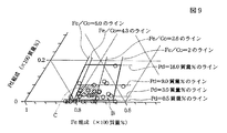
図9は、図8の領域Aの組成範囲内を拡大した部分三元図である。
実験によれば、Feの組成比X(質量%)/Coの組成比Y(質量%)を5質量%としたライン、Feの組成比X(質量%)/Coの組成比Y(質量%)を2としたライン、Pdの組成比を18質量%としたライン、Pdの組成比を0.5としたラインで囲まれる領域B内の組成範囲であれば、飽和磁束密度Bsを2.0T以上にでき、しかもPdを含まないFeCo合金に比べて耐食性に優れた軟磁性膜を製造することができることがわかった。
【0192】
次に、Feの組成比X(質量%)/Coの組成比Y(質量%)を4.3としたライン、Feの組成比X(質量%)/Coの組成比Y(質量%)を2.6としたライン、Pdの組成比を9質量%としたライン、Pdの組成比を3質量%としたラインで囲まれる領域C内の組成範囲であれば、飽和磁束密度Bsを2.2T以上にでき、しかもPdを含まないFeCo合金に比べて耐食性に優れた軟磁性膜を製造することができることがわかった。
【0193】
上記したFeの組成比X(質量%)/Coの組成比Y(質量%)の比率の範囲は、飽和磁束密度Bsとの関係から求めたものである。
【0194】
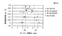
図10は、表1の各サンプルに示すFeの組成比X(質量%)/Coの組成比Y(質量%)の比率と飽和磁束密度Bsとの関係を示すグラフである。
【0195】
図10に示すように、Feの組成比X(質量%)/Coの組成比Y(質量%)を2以上で5以下にすれば確実に飽和磁束密度Bsを2.0T以上にできることがわかる。
【0196】
次に図10に示すように、Feの組成比X(質量%)/Coの組成比Y(質量%)を3から4程度にすると前記飽和磁束密度Bsを最も大きくでき、本発明ではこの実験結果から好ましい前記Feの組成比X(質量%)/Coの組成比Y(質量%)の比率を2.6以上で4.3以下とした。これによって飽和磁束密度Bsを2.2T以上確保できることがわかる。
【0197】
ただし前記飽和磁束密度Bsは、図10を見てわかるように、Pdの組成比にも依存する。当然のことながら前記Pdの組成比を大きくしていけば、Feの組成比X(質量%)/Coの組成比Y(質量%)を上記比率内に収めても、磁性を担うFe、Co量が減少するため、飽和磁束密度Bsは低下しやすくなる。
【0198】
また前記Pdは耐食性を向上させるために添加される貴金属である。耐食性の向上のためには前記Pdをある程度、FeCo系合金内に含有させないと、その効果を適切に発揮させることはできない。
【0199】
そこで次に前記Pdの組成比を限定することとした。
本発明ではFeCo系合金中に含まれるPdの組成比と耐食性との関係について実験を行った。実験は、表1から選択された6つのサンプルを用意して行った。各サンプルの膜構成は、Fe20Ni80合金膜/軟磁性膜/NiP合金膜/Fe60Ni40とした。
【0200】
表1からは、上記膜構成中の軟磁性膜としてパルス電流による電気メッキ法にてメッキ形成されたFe72Co28合金からなるサンプル2、Fe78.72Co20.78Pd0.5合金からなるサンプル11、Fe68Co27Pd5合金からなるサンプル24、Fe63.51Co26.59Pd9.9からなるサンプル32、Fe55.55Co26.9Pd17.55合金からなるサンプル33の5つを用意し、さらに新たに、Fe70Ni30からなるサンプル34を用意した。
【0201】
そしてこれら各サンプルを温純水(60℃)、純水(45℃)、市水(45℃)、希硫酸(pH=2)に浸し、その後、各サンプルを切断して耐食性の良否を評価した。評価は10段階の評価とし、10の評価は、軟磁性膜の部分が全く腐食されておらず、すなわち最も耐食性に優れていることを意味する。また10の評価から数字が1つ減る毎に、軟磁性膜の部分の腐食の度合が大きくなり、1の評価は、軟磁性膜の部分がほとんど腐食され、最も耐食性が悪いことを意味する。
その実験結果をまとめたのが以下の表2である。
【0202】
【表2】
表2に示すように、軟磁性膜にFe70Ni30合金膜を選択したサンプル34では、いずれの液に浸したときでも耐食性の評価が高く非常に耐食性に優れていることがわかった。
【0204】
これに対し、軟磁性膜にFe72Co28合金膜を選択したサンプル2では、温純水(60℃)及び市水(45℃)における耐食性の評価が3の評価と4の評価と低く、希硫酸に浸した時の評価はすべて5であり、腐食しやすいことがわかった。
【0205】
このように、軟磁性膜にFe72Co28合金膜を選択した場合、耐食性が低下する原因は、Fe72Co28合金膜の上にFe60Ni40合金膜を電気メッキ法にてメッキ形成するとき、前記FeCo合金膜とNiFe系合金膜との間に大きな電位差(標準電極電位差)が発生し、この電位差によりいわゆる電池効果が生じて前記FeCo合金膜が溶け出すからであると考えられる。
【0206】
一方、FeCo合金にPdを0.5質量%含有させたサンプル11では、Pdを含有しないサンプル2と比較して見ると、特に、希硫酸に浸した時、耐食性が改善されたことがわかる。希硫酸は、スライダ加工などで使用される洗浄液の一つであり、この希硫酸での耐食性の改善は、スライダ加工時に、さらに希硫酸を使用しやくなり好ましい。
【0207】
さらにPdの組成比を増やしたサンプル24、32及び33では、Pdを含まないサンプル2に比べて飛躍的に耐食性の向上を図ることができることがわかり、特にPdを17.55質量%含有させたサンプル33に至っては、Fe70Ni30合金よりも優れた耐食性を示した。
【0208】
このようにFeCo合金にPdを含有させたFeCoPd合金膜であるとPdを含まないFeCo合金膜より耐食性が向上する理由は、Pdはそれ自体イオン化され難い貴金属だからであり、前記PdがFeCo合金内に含有されることで、FeCoPd合金の上にFeNi合金を電気メッキ法にてメッキ形成するとき前記FeCoPd合金のイオン化を抑制でき、前記FeCoPd合金の耐食性を向上させることが可能になっている。
【0209】
この表から見て、本発明ではPd量を0.5質量%すると、Pdを含まないFeCo合金に比べて効果的に耐食性の向上を図ることが可能になることがわかる。
【0210】
Pd量を0.5質量%含有するサンプルNo.11は表1に示すように、Feの組成比X(質量%)/Coの組成比Y(質量%)は約3.78であり、飽和磁束密度Bsも2.0Tを越え約2.18Tとなっている。
【0211】
このようにサンプルNo.11では、Feの組成比X(質量%)/Coの組成比Y(質量%)が2以上で5以下の範囲内に収まり、飽和磁束密度Bsを2.0T以上得ることができるととともに、耐食性を、Pdを含まない軟磁性膜に比べて向上させることができることが確認されたので、本発明では、前記Pdの組成比の下限値を0.5質量%以上に設定した。
【0212】
次に、Pdを17.55質量%含有するサンプルNo.33では表1を見てみると、Feの組成比X(質量%)/Coの組成比Y(質量%)が約2.07である。上記したように本発明では、Feの組成比X(質量%)/Coの組成比Y(質量%)を2以上で5以下に設定している。すなわちこのサンプルNo.33では、Feの組成比X(質量%)/Coの組成比Y(質量%)が2付近であり、しかもPdの組成比は、他のサンプルに比べて最も高いため、Feの組成比(絶対値)が最も小さくなっている。サンプルNo.33ではFeの組成比は約55.55質量%である。
【0213】
サンプルNo.33では、他のサンプルに比べてFeの組成比が最も低いものの、飽和磁束密度Bsは依然として2.0Tを越えている。上記したようにBsはFe量に最も影響を受けるため、サンプルNo.33程度のPdの組成比であり、且つFeの組成比X(質量%)/Coの組成比Y(質量%)を2以上5以下にすれば、飽和磁束密度を2.0T以上確保できることがわかる。
【0214】
また表2を見てみると、Pdの組成比を17.55質量%としたサンプル33は耐食性をより効果的に向上させることができることがわかる。したがって本発明では、前記Pdの組成比の上限値を18質量%以下とした。
【0215】
以上の実験結果により、本発明では、Feの組成比X(質量%)/Coの組成比Y(質量%)を2以上で5以下とし、且つPdの組成比を0.5質量%以上で18質量%以下と設定した。これによって飽和磁束密度を2.0T以上にできると共に、Pdを含まないFeCo合金に比べて耐食性に優れた軟磁性膜を製造することが可能になる。
【0216】
次に、Feの組成比X(質量%)/Coの組成比Y(質量%)を2.6以上で4.3以下とし、2.2T以上の飽和磁束密度を得ることができる場合のPdの組成比を設定する。
【0217】
表1で示すように、Pdを含むものでFeの組成比X(質量%)/Coの組成比Y(質量%)が2.6以上で4.3以下であり、飽和磁束密度が2.2Tを越えているサンプルは、No.15、17、18、19、20、22、25、26、27である。またサンプルNo.30では、飽和磁束密度Bsがわずかに2.2Tを下回るもののPd量が約9質量%に高くても2.2Tに近い飽和磁束密度Bsを得ることが可能である。
【0218】
これらサンプルのPd量を見てみると、Pd量は、約3質量%から9質量%の範囲内であることがわかる。
【0219】
そこで本発明では、Feの組成比X(質量%)/Coの組成比Y(質量%)が2.6以上で4.3以下であり、且つPd量が3質量%以上で9質量%の範囲を好ましい組成範囲とした。これにより飽和磁束密度Bsが2.2T以上で、しかもPdを含まないFeCo合金に比べて耐食性に優れた軟磁性膜を製造することができる。
【0221】
次に、FeCoRhからなる軟磁性膜の組成比と飽和磁束密度Bsとの関係について調べた。
【0222】
(メッキ浴組成)
▲1▼FeSO4・7H2O 5.0g/l〜25.0g/l(Feイオン濃度は、1.0g/l〜5.0g/l)
▲2▼CoSO4・7H2O 0.4g/l〜20.0g/l(Coイオン濃度は、0.1g/l〜5.0g/l)
▲3▼Rh(SO4)3 0〜48mg/l(Rhイオン濃度は、0g/l〜10mg/l)
▲4▼サッカリンナトリウム 2g/l
▲5▼塩化ナトリウム 25g/l
▲6▼ホウ酸 25g/l
▲7▼ラウリル硫酸ナトリウム 0.02ml/l
また実験に際して以下の成膜条件を共通にした。
【0223】
まず電極のpHを1.7に設定した。また直流電流を用いた電気メッキ法で、前記FeCoRh合金をメッキ形成した。このときの電流値は500〜1000mAであった。
【0224】
そして本発明では、Si基板上にCu下地層をスパッタ形成した後、前記Cu下地層上に上記のメッキ浴からFeCoRh合金あるいはFeCo合金を0.5μm〜1μmの膜厚でメッキ形成した。
その実験結果は、以下の表3に示されている。
【0225】
【表3】
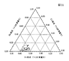
表3に示されたFe、Co及びRhの各組成比と飽和磁束密度Bsとの関係をまとめたのが図11の三元図である。
【0227】
図12は、図11の一部の組成範囲内を拡大した部分三元図である。
実験によれば、Fe組成比Xを56質量%としたライン、Co組成比を20質量%としたライン、Rhの組成比を1.7質量%としたライン、Rhの組成比を20質量%としたラインで囲まれる領域内の組成範囲であれば、飽和磁束密度Bsを2.1T以上にでき、しかも以下に説明するようにRhを含まないFeCo合金に比べて耐食性に優れた軟磁性膜を製造することができることがわかった。
【0228】
次に上記した組成範囲内で形成されたFeCoRh合金の耐食性について調べた。実験では前記FeCoRh合金をべた膜でメッキ形成し、このメッキ膜を希硫酸(pH=2)、希硫酸(pH=4)及び温純水(60℃)に浸したときのエッチング量を調べた。その実験結果は表4に示されている。
【0229】
【表4】
表4に示すように、Rhが1.7質量%以上含まれていれば、FeCo合金膜よりもエッチング量を小さくできることがわかった。
【0231】
以上の実験結果から本発明では、FeCoRh合金のFe量を56質量%以上とし、Co量を20質量%以上とし、およびRh量を1.7質量%以上で20質量%以下とすれば、飽和磁束密度Bsを2.1T以上にできると共に、耐食性をFeCo合金よりも良好にできることがわかった。
【0232】
次に本発明では、図1ないし図4に示す実施形態のように、下部磁極層19、32、ギャップ層20、33及び上部磁極層21、34を連続メッキ形成したときの下部磁極層19、32及び上部磁極層21、34の耐食性について調べた。実験では下部磁極層19、32をFeCoRh合金膜でメッキ形成し、ギャップ層20、33をNiP合金膜でメッキ形成し、上部磁極層21、34を下からFeCoRh合金、およびFeNi合金の2層でメッキ形成した。
【0233】
そして実験で使用したFeCoRh合金膜の組成比の異なる各サンプルを希硫酸(pH=4)及び温純水(60℃)に浸し、どの程度エッチングされたかを官能評価した。なお実験では、上記したFeCoRh合金膜で形成された部分をFeCo合金膜で形成したサンプル、及びFeNi合金膜で形成したサンプルも用意し、これらサンプルについても同様の耐食性実験を行った。その実験結果は表5に示されている。
【0234】
【表5】
なお表5に示す官能評価は10段階の評価とし、10の評価は、軟磁性膜の部分が全く腐食されておらず、すなわち最も耐食性に優れていることを意味する。また10の評価から数字が1つ減る毎に、軟磁性膜の部分の腐食の度合が大きくなり、1の評価は、軟磁性膜の部分がほとんど腐食され、最も耐食性が悪いことを意味する。
【0236】
表5に示すように、下部磁極層及び上部磁極層をFeCo合金膜で形成したサンプルでは、そもそもメッキ形成が不可能で耐食性評価を行うことができなかった。
【0237】
一方、Rhを2.6質量%混入したFeCoRh合金膜では、FeCo合金膜よりも耐食性は向上するものの、官能評価はすべて「1」でかなりエッチングされてしまい耐食性は特にNiFe合金膜に比べると非常に悪かった。
【0238】
これに対し、Rhを7.5質量%以上混入したFeCoRh合金膜では、FeNi合金と同等の耐食性を得ることができることがわかった。
【0239】
以上の実験結果から特に連続メッキで形成する部分に、FeCoRh合金膜を使用する場合、Rhを7.5質量%以上にすることが好ましいことがわかった。
【0240】
次に本発明のより好ましい組成範囲について以下に説明する。本発明では飽和磁束密度Bsが2.2T以上あり、しかも耐食性がNiFe合金膜と同等程度あるFeCoRh合金であることがより好ましい。その組成範囲は表3や表5から算出すると、図12に示すFeの組成比X(質量%)/Coの組成比Y(質量%)を2.030としたライン、Feの組成比X(質量%)/Coの組成比Y(質量%)を2.704としたライン、Rhの組成比を7.5質量%としたライン、Rhの組成比を10質量%としたラインで囲まれる領域内であることがわかった。従って本発明では、FeCoRh合金膜のより好ましい組成範囲を、Feの組成比X(質量%)/Coの組成比Y(質量%)が2.030以上で2.704以下で、Rhの組成比が7.5質量%以上で10質量%以下である範囲内であるとした。
【0241】
【発明の効果】
以上詳述した本発明では、Feの組成比X(質量%)/Coの組成比Y(質量%)の比率が2以上で5以下であり、元素α(ただし元素αは、Pd)の組成比Zが、0.5質量%以上で18質量%以下であり、X+Y+Z=100質量%の関係を満たし、且つメッキ形成されるFeXCoYαZ合金であれば、2.0T以上の飽和磁束密度を得ることができると共に元素αを含まないFeCo合金に比べて耐食性に優れた軟磁性膜を製造することができる。
【0242】
また本発明では、前記Feの組成比X(質量%)/Coの組成比Y(質量%)の比率は2.6以上で4.3以下であり、元素αの組成比Zは3質量%以上で9質量%以下であり、X+Y+Z=100質量%の関係を満たすことが好ましい。これにより飽和磁束密度Bsを2.2T以上にすることができるとともに元素αを含まないFeCo合金に比べて耐食性に優れた軟磁性膜を製造することができる。
【0246】
また本発明では前記FeCoα合金に元素β(ただし元素βはNi、Crの一方あるいは両方)を添加してもよい。
【0247】
本発明では、前記FeCoα合金をパルス電流を用いた電気メッキ法あるいは直流電流を用いた電気メッキ法によりメッキ形成することで、上記した組成比を有する前記FeCoα合金を再現性良く形成することができる。
【0248】
以上のようにして形成されたFeCoα合金を薄膜磁気ヘッドの磁極層やコア層に使用することにより、前記磁極層やコア層のギャップ近傍に磁束を集中させて記録密度を向上させることが可能である。したがって今後の高記録密度化に対応可能な薄膜磁気ヘッドを製造することができる。しかも耐食性に優れた薄膜磁気ヘッドを製造することができる。
【図面の簡単な説明】
【図1】本発明の第1実施形態の薄膜磁気ヘッドの部分正面図、
【図2】図1の縦断面図、
【図3】本発明の第2実施形態の薄膜磁気ヘッドの部分正面図、
【図4】図3の縦断面図、
【図5】本発明の第3実施形態の薄膜磁気ヘッドの縦断面図、
【図6】本発明の第4実施形態の薄膜磁気ヘッドの縦断面図、
【図7】本発明の第5実施形態の薄膜磁気ヘッドの縦断面図、
【図8】電気メッキ法によりメッキ形成されたFeCoPd合金とFeCo合金の組成比と飽和磁束密度との関係を示す三元図、
【図9】図8の領域Aの部分を拡大した部分三元図、
【図10】Feの質量%/Coの質量%の比率と飽和磁束密度との関係を示すグラフ、
【図11】電気メッキ法によりメッキ形成されたFeCoRh合金とFeCo合金の組成比と飽和磁束密度との関係を示す三元図、
【図12】図11のある所定領域の部分を拡大した部分三元図、
【符号の説明】
11 スライダ
10 磁気抵抗効果素子
16 下部コア層(上部シールド層)
18、30 磁極部
19、32、50 下部磁極層
20、33 ギャップ層
21、34 上部磁極層
22、40、46、55 上部コア層
41 磁気ギャップ層
47 高Bs層
48 上層[0001]
BACKGROUND OF THE INVENTION
The present invention relates to a soft magnetic film used as a core material of a thin film magnetic head, for example, and the saturation magnetic flux density Bs is 2.0 T or more by using FeCoα or FeCoRh (element α is a noble metal) alloy for the soft magnetic film. And a thin film magnetic head using the soft magnetic film, a method of manufacturing the soft magnetic film, and a method of manufacturing the thin film magnetic head.
[0002]
[Prior art]
For example, for the core layer of a thin film magnetic head, a magnetic material having a high saturation magnetic flux density Bs is used for the recording layer especially in the future, and the magnetic flux is concentrated near the gap of the core layer to improve the recording density. It is necessary to let
[0003]
Conventionally, NiFe-based alloys are often used as the magnetic material. The NiFe alloy was plated by an electroplating method using a direct current, and a saturation magnetic flux density Bs of about 1.8 T could be obtained.
[0004]
[Problems to be solved by the invention]
However, as the recording density increases in the future, it becomes necessary to produce a soft magnetic film that satisfies a higher saturation magnetic flux density Bs, and NiFe-based alloys cannot sufficiently meet the demand.
[0005]
In addition to NiFe alloys, a soft magnetic material often used is an FeCo alloy film. In the FeCo alloy film, the saturation magnetic flux density Bs higher than that of the NiFe-based alloy film can be obtained by appropriately adjusting the composition ratio of Fe, but the following problems occur.
[0006]
Depending on the configuration of the thin film magnetic head and other magnetic elements, the NiFe-based alloy may be stacked on the FeCo alloy, or the FeCo alloy may be stacked above and below a plated nonmagnetic layer (for example, a gap layer). However, when the FeCo alloy film is formed by electroplating, there is a problem that the FeCo alloy film ionizes and melts and corrodes.
[0007]
This is because a large potential difference (standard electrode potential difference) is generated between the FeCo alloy film and the NiFe-based alloy film or between the FeCo alloy film and the nonmagnetic layer. It is considered to be issued.
[0008]
Even when the FeCo alloy film is formed as a single layer, corrosion resistance is required in the method of manufacturing a thin film magnetic head and other magnetic elements. For example, it is required not to corrode even when exposed to a slider grinding process or an element cleaning process. Corrosion resistance is also required for environmental factors in the use of thin film magnetic heads.
[0009]
Therefore, a soft magnetic film used for a core layer of a thin film magnetic head needs not only high saturation magnetic flux density Bs but also excellent corrosion resistance.
[0010]
Therefore, the present invention is to solve the above-mentioned conventional problems, and by adding a noble metal element such as Pd or Rh to the FeCo alloy, the saturation magnetic flux density Bs can be increased to 2.0 T or more, and at the same time, the corrosion resistance is improved. An object is to provide an excellent soft magnetic film, a thin film magnetic head using the soft magnetic film, a method for manufacturing the soft magnetic film, and a method for manufacturing the thin film magnetic head.
[0036]
[Means for Solving the Problems]
The method for producing a soft magnetic film in the present invention is as follows.The Fe ion concentration in the plating bath is 1.2 g / l or more and 3.2 g / l or less, the Co ion concentration is 0.86 g / l or more and 1.6 g / l or less, and the element α ion concentration is 0.2 mg. The ratio of Fe composition ratio X (mass%) / Co composition ratio Y (mass%) is 2 or more and 5 or less, and element α (however element α isPdThe composition ratio Z is 0.5 mass% or more and 18 mass% or less, and satisfies the relationship of X + Y + Z = 100 mass%.XCoYαZAn alloy is formed by plating. With a soft magnetic film having this composition ratio, the saturation magnetic flux density Bs can be made 2.0 T or more, and a soft magnetic film excellent in corrosion resistance as compared with an FeCo alloy containing no element α can be manufactured.
[0037]
In the present invention, the ratio of Fe composition ratio X (mass%) / Co composition ratio Y (mass%) is 2.6 or more and 4.3 or less, and the composition ratio Z of element α is 3 mass%. The amount of Fe is 9% by mass or less and satisfies the relationship of X + Y + Z = 100% by mass.XCoYαZPreferably, the alloy is plated. With a soft magnetic film having this composition ratio, it is possible to produce a soft magnetic film having a saturation magnetic flux density Bs of 2.2 T or higher and excellent in corrosion resistance as compared with an FeCo alloy containing no element α.
[0039]
According to the experimental results to be described later, by having the above plating bath composition, the ratio of Fe composition ratio X (mass%) / Co composition ratio Y (mass%) is surely 2 or more and 5 or less, The composition ratio Z of the element α is 0.5% by mass or more and 18% by mass or less, and satisfies the relationship of X + Y + Z = 100% by mass.XCoYαZThe ratio of the alloy, preferably the Fe composition ratio X (mass%) / Co composition ratio Y (mass%) is 2.6 or more and 4.3 or less, and the composition ratio Z of the element α is 3 mass%. The amount of Fe is 9% by mass or less and satisfies the relationship of X + Y + Z = 100% by mass.XCoYαZAlloys can be plated.
[0040]
In the present invention, β ions (where element β is one or both of Ni and Cr) are added to the plating bath, and the FeXCoYαZFe containing element β having a composition ratio V of 0.5% by mass or more and 5% by mass or less in the alloy and satisfying the relationship of X + Y + Z + V = 100% by massXCoYαZβVAn alloy may be plated.
[0047]
As described above, in the present invention, preferably FeCoα compound is used.MoneyPlating is performed by electroplating using a pulse current. In the electroplating method using a pulse current, for example, the current control element is repeatedly turned on and off, and a time for flowing current and a blank time for not flowing current are provided during plating formation. By providing a time during which no current flows in this way, the FeCoα alloyMembraneIt is possible to alleviate the uneven distribution of current density during plating as compared with the conventional case where the plating is formed little by little and a direct current is used. According to the electroplating method using a pulse current, the Fe content contained in the soft magnetic film can be easily adjusted as compared with the electroplating method using a direct current, and a large amount of the Fe content can be taken into the film.
[0048]
In the present invention, the FeCoα alloy, the FeCoαβ compoundof goldIt is preferable to mix sodium saccharin in the plating bath. Saccharin sodium (C6H4CONNaSO2) Has a role as a stress relaxation agent. Therefore, by mixing the saccharin sodium, the FeCoα alloy and FeCoαβ compound are mixed together.of goldIt is possible to reduce the film stress.
[0049]
Moreover, in this invention, it is preferable to mix 2-butyne-1 and 4 diol in the said plating bath. FeCoα alloy and FeCoαβ alloy formed by platingof goldThe coarsening of the crystal grain size is suppressed, and when the crystal grain size becomes small, voids are hardly generated between the crystals, and the surface roughness of the film surface is suppressed. Since the surface roughness can be suppressed, the coercive force Hc can be reduced.
[0050]
In the present invention, sodium 2-ethylhexyl sulfate is preferably mixed in the plating bath. As a result, hydrogen generated in the plating bath is removed by sodium 2-ethylhexyl sulfate, which is a surfactant, and surface roughness due to adhesion of the hydrogen to the plating film can be suppressed.
[0051]
In addition, sodium lauryl sulfate may be used in place of the sodium 2-ethylhexyl sulfate. However, when 2-ethylhexyl sodium sulfate is used, there is less foaming when mixed in the plating bath. A large amount of sodium can be mixed in the plating bath, and the hydrogen can be removed more appropriately.
[0052]
The present invention also includes a lower core layer made of a magnetic material, an upper core layer facing the lower core layer through a magnetic gap on the surface facing the recording medium, a coil layer for inducing a recording magnetic field in both core layers, In a method of manufacturing a thin film magnetic head having
At least one of the core layers is plated with a soft magnetic film by the manufacturing method described above.
[0053]
In the present invention, it is preferable that the lower magnetic pole layer is formed on the lower core layer so as to protrude from the surface facing the recording medium, and the lower magnetic pole layer is formed by plating with the soft magnetic film.
[0054]
In the present invention, the lower core layer and the upper core layer are located between the lower core layer and the upper core layer, and the width dimension in the track width direction is regulated to be shorter than that of the lower core layer and the upper core layer. Having a magnetic pole part,
The magnetic pole part is formed of a lower magnetic pole layer continuous with the lower core layer, an upper magnetic pole layer continuous with the upper core layer, and a gap layer located between the lower magnetic pole layer and the upper magnetic pole layer, or the magnetic pole part An upper magnetic pole layer continuous with the upper core layer, and a gap layer positioned between the upper magnetic pole layer and the lower core layer,
At this time, the upper magnetic pole layer and / or the lower magnetic pole layer is formed by plating with a soft magnetic film by the manufacturing method described above.
[0055]
In the present invention, the upper magnetic pole layer is preferably formed by plating with the soft magnetic film, and the upper core layer is formed by plating with an NiFe-based alloy film on the upper magnetic pole layer by electroplating.
[0056]
In the present invention, the core layer is formed of two or more magnetic layers at least in a portion adjacent to the magnetic gap, or the pole layer is formed of two or more magnetic layers. The magnetic layer in contact with the magnetic gap is preferably formed by plating with the soft magnetic film.
[0057]
In the present invention, it is preferable that other magnetic layers other than the magnetic gap layer are plated with a NiFe alloy by electroplating.
[0058]
As described above, the FeCoα alloy and the FeCoαβ alloy as the soft magnetic film in the present invention are formed by electroplating, whereby the ratio of Fe composition ratio X (mass%) / Co composition ratio Y (mass%). Is 2 or more and 5 or less, and element α (where element α isPdThe composition ratio Z is 0.5 mass% or more and 18 mass% or less. Preferably, the ratio of Fe composition ratio X (mass%) / Co composition ratio Y (mass%) is 2.6 or more. 4.3 or less, and the composition ratio Z of the element α is 3% by mass or more and 9% by mass or less.XCoYαZFe and alloy whose composition ratio V of element β is 0.5 mass% or more and 5 mass% or lessXCoYαZβVAlloys can be plated.
[0060]
When such a soft magnetic film is used as a core material of a thin film magnetic head, the saturation magnetic flux density Bs can be increased and the recording density can be increased, and when an FeCo alloy containing no element α or Rh is used. Compared with this, it is possible to manufacture a thin film magnetic head excellent in corrosion resistance with a high yield.
[0061]
DETAILED DESCRIPTION OF THE INVENTION
FIG. 1 is a partial front view of the thin film magnetic head according to the first embodiment of the present invention, and FIG. 2 is a longitudinal sectional view of the thin film magnetic head shown in FIG.
[0062]
The thin film magnetic head according to the present invention is formed on the side end face 11a of the
[0063]
The MR head h1 uses a magnetoresistive effect to detect a leakage magnetic field from a recording medium such as a hard disk and read a recording signal.
[0064]
As shown in FIG. 2, Al is formed on the trailing side end surface 11a of the slider 11.2OThreeA
[0065]
On the
[0066]
Next, in the embodiment shown in FIGS. 1 and 2, the
[0067]
Further, as shown in FIG. 1, the
[0068]
As shown in FIG. 2, a
[0069]
The
[0070]
The lower
[0071]
As a specific embodiment of the present invention, NiP is used for the
[0072]
Further, the upper
[0073]
When the
[0074]
The
[0075]
As shown in FIG. 1, the
[0076]
As shown in FIGS. 1 and 2, insulating
[0077]
As shown in FIG. 2, a
[0078]
As shown in FIG. 2, the
[0079]
As shown in FIG. 2, the
[0080]
In the present invention, the upper
(1) The composition formula is FeXCoYαZ(However, the element α isPdThe ratio of Fe composition ratio X (mass%) / Co composition ratio Y (mass%) is 2 or more and 5 or less, and the composition ratio Z of element α is 0.5 mass% or more. A soft magnetic film that is 18% by mass or less, satisfies the relationship of X + Y + Z = 100% by mass, and is formed by plating.
[0081]
From the experimental results to be described later, it was confirmed that the saturation magnetic flux density Bs can be set to 2.0 T or more for the FeCoα alloy having the above composition ratio. Thus, in the present invention, it is possible to obtain a saturation magnetic flux density Bs higher than that of the NiFe-based alloy.
[0082]
Fe and Co are elements responsible for magnetism. By setting the composition ratio of Fe and Co to an appropriate value, a high saturation magnetic flux density can be obtained. According to an experiment described later, when the ratio of the Fe composition ratio X (mass%) / Co composition ratio Y (mass%) is 2 or more and 5 or less, it is confirmed that the Bs can be 2.0 T or more. It was.
[0083]
Next, the element α is an element added to increase the corrosion resistance. If the element α is too small, the corrosion resistance cannot be improved effectively. The decrease causes a decrease in the saturation magnetic flux density Bs. In the present invention, by setting the composition ratio Z of the element α to 0.5 mass% or more and 18 mass% or less, the saturation magnetic flux density Bs can be made 2.0 T or more, and at the same time, a soft magnetic film made only of Co and Fe. Can also effectively improve the corrosion resistance. Moreover, when any one or two or more of Pd and Pt are added among the elements α, the corrosion resistance can be improved more effectively. In particular, the element α is preferably Pd.
[0084]
In addition, the FeCoα alloy having the above composition ratio can reduce the surface roughness of the film by forming crystals densely, improve the corrosion resistance, and reduce the coercive force Hc. Specifically, the coercive force can be 2000 (A / m) or less.
[0085]
When the FeCoα alloy is within the above composition range, a specific resistance of 15 (μΩ · cm) or more can be obtained. Further, the film stress can be 400 MPa or less. Furthermore, with respect to the anisotropic magnetic field Hk, an anisotropic magnetic field Hk comparable to that of a NiFe-based alloy that has been conventionally used as a soft magnetic material can be obtained.
[0086]
In the present invention, the ratio of the Fe composition ratio X (mass%) / Co composition ratio Y (mass%) is 2.6 or more and 4.3 or less, and the composition ratio Z of the element α is 3 mass%. It is 9 mass% or less above, and it is preferable to satisfy | fill the relationship of X + Y + Z = 100 mass%. As a result, the saturation magnetic flux density Bs can be increased to 2.2 T or more, and the corrosion resistance can be effectively improved as compared with the FeCo alloy not containing the element α.
[0087]
In the present invention, the element β (where element β is one or both of Ni and Cr) is added to the FeCoα alloy, that is, the composition formula is FeXCoYαZβVThe ratio of Fe composition ratio X (mass%) / Co composition ratio Y (mass%) is 2 or more and 5 or less, and the composition ratio Z of element α is 0.5 mass% or more and 18 The ratio of Fe composition ratio X (mass%) / Co composition ratio Y (mass%) is 2.6 or more and 4.3 or less, and the composition ratio Z of element α is preferably less than or equal to mass%. Is a soft magnetic film satisfying the relationship of X + Y + Z + V = 100% by mass, the composition ratio V of the element β being 0.5% by mass to 5% by mass. May be.
[0088]
By forming the upper
[0089]
As described above, in the present invention, since the above-described FeCoα alloy or FeCoαβ alloy can obtain a high saturation magnetic flux density Bs of 2.0 T or more, preferably 2.2 T or more, the FeCoα alloy or FeCoαβ alloy is used. By using the upper
[0090]
(2) The composition formula is FeXCoYRhwFe composition ratio X (mass%) is 56 mass% or more, Co composition ratio Y is 20 mass% or more, and Rh composition ratio W is 1.7 mass% or more and 20 mass% or less. A soft magnetic film that satisfies the relationship of X + Y + W = 100 mass% and is formed by plating.
[0091]
From the experimental results described later, it was confirmed that the saturation magnetic flux density Bs can be made 2.1 T or more in the case of the FeCoRh alloy having the above composition ratio. Thus, in the present invention, it is possible to obtain a saturation magnetic flux density Bs higher than that of the NiFe-based alloy.
[0092]
Fe and Co are elements responsible for magnetism. By setting the composition ratio of Fe and Co to an appropriate value, a high saturation magnetic flux density can be obtained. According to the experiment described later, it was confirmed that the Bs could be 2.1 T or more when the Fe composition ratio X was 56 mass% or more and the Co composition ratio Y was 20 mass% or more.
[0093]
Next, the Rh is an element added to enhance the corrosion resistance, and if the Rh is too small, the corrosion resistance cannot be improved effectively. The saturation magnetic flux density Bs is reduced. In the present invention, the saturation magnetic flux density Bs can be made 2.1 T or more by setting the composition ratio W of Rh to 1.7 mass% or more and 20 mass% or less, and at the same time, compared with a soft magnetic film made of only Co and Fe. Corrosion resistance can be improved effectively.
[0094]
In addition, the FeCoRh alloy having the above composition ratio can reduce the surface roughness of the film by forming crystals densely, improve the corrosion resistance, and reduce the coercive force Hc. Specifically, the coercive force can be 2000 (A / m) or less.
[0095]
When the FeCoRh alloy is within the above composition range, a specific resistance of 15 (μΩ · cm) or more can be obtained. Further, the film stress can be 400 MPa or less. Furthermore, with respect to the anisotropic magnetic field Hk, an anisotropic magnetic field Hk comparable to that of a NiFe-based alloy that has been conventionally used as a soft magnetic material can be obtained.
[0096]
The composition ratio W of Rh is preferably 7.5% by mass or more. It has been found by experiments described later that this makes it possible to obtain corrosion resistance equivalent to that of the NiFe alloy film. In particular, as shown in FIGS. 1 and 2, when the
[0097]
In the present invention, the ratio of Fe composition ratio X (mass%) / Co composition ratio Y (mass%) is 2.030 or more and 2.704 or less, and Rh composition ratio W is 7.5 mass. % To 10% by mass, and preferably satisfies the relationship of X + Y + W = 100% by mass. According to the experiment described later, the saturation magnetic flux density Bs can be increased to 2.2 T or more by keeping the composition range of each element within the above range, and the same corrosion resistance as the NiFe alloy conventionally used for the core material or the like. Can be obtained.
[0098]
In the present invention, the element β (where element β is one or both of Ni and Cr) is added to the FeCoRh alloy, that is, the composition formula is FeXCoYRhwβVFe composition ratio X is 56 mass% or more, Co composition ratio Y is 20 mass% or more, and Rh composition ratio W is 1.7 mass% or more and 20 mass% or less, preferably The composition ratio W of Rh is 7.5% by mass or more, more preferably, the ratio of the Fe composition ratio X (mass%) / Co composition ratio Y (mass%) is 2.030 or more and 2 .704 or less, the composition ratio W of Rh is 7.5 mass% or more and 10 mass% or less, and the composition ratio V of the element β is 0.5 mass% or more and 5 mass% or less, and X + Y + W + V = A soft magnetic film satisfying the relationship of 100 mass% may be used.
[0099]
By forming the upper
[0100]
As described above, in the present invention, since the above-described FeCoRh alloy or FeCoRhβ alloy can obtain a high saturation magnetic flux density Bs of 2.1 T or more, preferably 2.2 T or more, the FeCoRh alloy or FeCoRhβ alloy is used. By using the upper
[0101]
The soft magnetic films (1) and (2) described above can also be used in the structure of a thin film magnetic head described below.
[0102]
FIG. 3 is a partial front view showing the structure of the thin film magnetic head according to the second embodiment of the present invention. FIG. 4 is a longitudinal sectional view of the thin film magnetic head taken along line 4-4 shown in FIG. is there.
[0103]
In this embodiment, the structure of the MR head h1 is the same as that shown in FIGS.
As shown in FIG. 3, an insulating
[0104]
The track
[0105]
The lower
[0106]
As a specific embodiment of the present invention, NiP is used for the
[0107]
The
[0108]
On the
[0109]
Further, the upper
[0110]
When the
[0111]
As shown in FIG. 4, a
[0112]
As shown in FIG. 3, on both side end surfaces of the track
[0113]
As shown in FIG. 3, the
[0114]
As shown in FIG. 4, the
[0115]
In the second embodiment shown in FIGS. 3 and 4, the lower
[0116]
In the embodiment shown in FIGS. 1 to 4, the
[0117]
The upper core layers 22 and 40 preferably have a high specific resistance rather than a saturation magnetic flux density Bs. In order to properly guide the recording magnetic field from the upper core layers 22 and 40 to the upper magnetic pole layers 21 and 34 during recording in the high frequency band, eddy current loss occurs in the upper core layers 22 and 40. Therefore, in the present invention, it is possible to increase the recording density by using, for the upper core layers 22 and 40, the NiFe-based alloy having a higher specific resistance than the soft magnetic film (1) or (2). It is effective in planning. The upper core layers 22 and 40 may be made of Ni, for example.80Fe20An alloy is used.
[0118]
By the way, in the present invention, the soft magnetic film (1) or (2) is used as the upper magnetic pole layers 21 and 34, and the NiFe-based alloy is used as the upper core layers 22 and 40. When the
[0119]
The element α or Rh in the present invention is a noble metal that is not easily ionized, and by adding these elements, it is possible to prevent the upper magnetic pole layers 21 and 34 from being ionized.
[0120]
Alternatively, when using the FeCoαβ alloy or the FeCoRhβ alloy as the upper magnetic pole layers 21 and 34, in addition to the element α or Rh that is not easily ionized, Ni or Cr that easily forms a passive film on the surface is added. The ionization of the upper magnetic pole layers 21 and 34 can be effectively suppressed, and a magnetic pole having a high saturation magnetic flux density Bs and excellent corrosion resistance can be formed.
[0121]
The lower magnetic pole layers 19 and 32 are also preferably formed of the soft magnetic film of the above (1) or (2), whereby the lower magnetic pole layers 19 and 32 when the upper core layers 22 and 40 are plated are formed. 32 ionization can be effectively suppressed.
[0122]
In the present invention, the lower magnetic pole layers 19 and 32 and / or the upper magnetic pole layers 21 and 34 may be formed by laminating two or more magnetic layers. In such a configuration, the magnetic layer on the side in contact with the gap layers 20 and 33 is preferably formed of the soft magnetic film (1) or (2). As a result, the magnetic flux can be more concentrated in the vicinity of the gap, and it is possible to manufacture a thin film magnetic head that can cope with a future increase in recording density.
[0123]
Further, the magnetic layer other than the magnetic layer in contact with the gap layers 20 and 33 may be formed of a magnetic material of any material and composition ratio, but is more saturated than the magnetic layer on the side in contact with the gap layers 20 and 33. The magnetic flux density Bs is preferably small. For example, the other magnetic layer is preferably formed of a NiFe-based alloy. As a result, a recording magnetic field can be appropriately guided from the other magnetic layer to the magnetic layer on the side in contact with the gap layers 20 and 33 to increase the recording density, and when the other magnetic layer is formed by plating. The ionization of the magnetic layer on the side in contact with the gap layers 20 and 33 can be appropriately prevented.
[0124]
The other magnetic layer need not be formed of a NiFe-based alloy, and may be formed of the soft magnetic film (1) or (2) described above, but the magnetic layer on the side in contact with the gap layers 20 and 33 may be used. It is preferable to appropriately adjust the composition ratio so as to have a saturation magnetic flux density Bs lower than that of the layer. As the method, the amount of Fe may be reduced as compared with the magnetic layer on the side in contact with the gap layers 20 and 33.
[0125]
The saturation magnetic flux density Bs of the lower magnetic pole layers 19 and 32 is preferably high. However, the leakage magnetic field between the lower magnetic pole layer and the upper magnetic pole layer can be reduced by making it lower than the saturation magnetic flux density Bs of the upper magnetic pole layers 21 and 34. Makes it easier to reverse the magnetization of the recording medium, the signal writing density to the recording medium can be increased.
[0126]
When the nonmagnetic gap layers 20 and 33 are plated between the lower magnetic pole layers 19 and 32 and the upper magnetic pole layers 21 and 34 as shown in FIGS. 1 to 4, the lower magnetic pole layers 19 and 32 and the upper magnetic pole layer are formed. The corrosion resistance of 21 and 34 is preferably comparable to that of the NiFe alloy film. This is because when the magnetic pole layer and the gap layer are formed by plating, the magnetic pole layer is melted and cannot be properly formed by plating. Therefore, in the present invention, the soft magnetic film (1) described above or the soft magnetic film (2) having Rh of 7.5 mass% or more is used for the lower magnetic pole layers 19 and 32 and the upper magnetic pole layers 21 and 34. Is preferred.
[0127]
FIG. 5 is a longitudinal sectional view of a thin film magnetic head according to a third embodiment of the present invention.
In this embodiment, the MR head h1 is the same as in FIG. As shown in FIG. 5, a magnetic gap layer (nonmagnetic material layer) 41 made of alumina or the like is formed on the
[0128]
Further, the
[0129]
As shown in FIG. 5, the
[0130]
In the present invention, the
[0131]
The
[0132]
Unlike FIG. 1 to FIG. 4, the
[0133]
FIG. 6 is a longitudinal sectional view of a thin film magnetic head according to a fourth embodiment of the present invention.
The difference from FIG. 5 is that the
[0134]
The
[0135]
The
[0136]
Although the
[0137]
Although the NiFe alloy has a lower saturation magnetic flux density Bs than the FeCoα alloy, FeCoNiα alloy, FeCoRh alloy, and FeCoRhβ alloy in the present invention, the specific resistance is higher. As a result, the
[0138]
Further, since the
[0139]
In the present invention, as shown in FIG. 6, the
[0140]
The
[0141]
In the embodiment shown in FIG. 6, the
[0142]
Further, when the
[0143]
FIG. 7 is a longitudinal sectional view of a thin film magnetic head according to a fifth embodiment of the present invention.
In the embodiment of FIG. 7, the configuration of the MR head h1 is the same as that of FIG. As shown in FIG. 7, a lower
[0144]
A
[0145]
As shown in FIG. 7, the
[0146]
A
[0147]
In this embodiment, the
[0148]
Since the lower
[0149]
In FIG. 7, when the lower
[0150]
The
[0151]
In each embodiment, the
[0152]
Next, a general manufacturing method of the thin film magnetic head shown in FIGS. 1 to 7 will be described below.
[0153]
The thin film magnetic head shown in FIGS. 1 and 2 has a
[0154]
The thin film magnetic head shown in FIGS. 3 and 4 has an insulating
[0155]
A lower
[0156]
In the thin film magnetic head shown in FIGS. 5 and 6, a
[0157]
In the thin film magnetic head shown in FIG. 7, a lower
[0158]
Next, the ratio of Fe composition ratio X (mass%) / Co composition ratio Y (mass%) in the present invention is 2 or more and 5 or less, and element α (where element α isPdFe) satisfying the relationship X + Y + Z = 100% by mass with a composition ratio Y of 0.5% by mass or more and 18% by mass or less.XCoYαZThe alloy plating method will be described below.
[0159]
In the present invention, the FeCoα alloy is formed by electroplating.
[0160]
Examples of the electroplating method include an electroplating method using a direct current and an electroplating method using a pulse current. In the present invention, it is possible to use an electroplating method using a direct current.
[0161]
However, it is preferable to use an electroplating method using a pulse current for the following reasons.
[0162]
In the electroplating method using a pulse current, for example, the current control element is repeatedly turned on and off, and a time for flowing current and a blank time for not flowing current are provided during plating formation. By providing a time during which no current flows in this way, the FeCoα alloy film is formed by plating little by little, and the current density distribution at the time of plating formation is alleviated compared to the case of using direct current as in the past. Is possible.
[0163]
The pulse current is preferably turned ON / OFF in a cycle of several seconds, for example, and the duty ratio is preferably about 0.1 to 0.5. The condition of the pulse current affects the average crystal grain size of the FeCoα alloy and the center line average roughness Ra of the film surface.
[0164]
As described above, the electroplating method using the pulse current can alleviate the uneven distribution of the current density during the plating formation.
[0165]
In the present invention, the Fe ion concentration is 1.2 g / l or more and 3.2 g / l or less, the Co ion concentration is 0.86 g / l or more and 1.6 g / l or less, and the element α ion concentration is 0.2 mg. / L to 6 mg / l. As shown in the experimental results to be described later, the ratio of the Fe composition ratio X (mass%) / Co composition ratio Y (mass%) can be surely set to 2 or more and 5 or less when the ratio is the above ratio. The composition ratio Z can be 0.5 mass% or more and 18 mass% or less.
[0166]
The above plating bath composition is characterized in that the ion concentration of Fe is lower than the conventional one. Conventionally, the Fe ion concentration was about 4.0 g / l, for example, but the stirring effect can be increased by lowering the concentration, and the Fe content of the FeCoα alloy can be increased more appropriately. A dense crystal can be formed, and an FeCoα alloy having excellent corrosion resistance can be obtained.
[0167]
In the present invention, the ratio of the Fe composition ratio X (mass%) / Co composition ratio Y (mass%) is 2.6 or more and 4.3 or less, and the composition ratio Z of the element α is 3 mass% or more. Fe that satisfies the relationship of X + Y + Z = 100% by mass.XCoYαZThe alloy is preferably formed by plating, and an FeCoα alloy having the above composition ratio can be easily manufactured by appropriately adjusting the above-described plating bath composition. In the FeCoα alloy formed in the above composition range, the saturation magnetic flux density Bs can be set to 2.2 T or more.
[0168]
Further, in the present invention, by including element β ions in the plating bath, FeXCoYαZβVAlloys can be plated. The element β ion concentration is preferably 0.3 g / l or more and 1 g / l or less, whereby the composition ratio V of the element β can be 0.5 mass% or more and 5 mass% or less, and X + Y + Z + V = Fe satisfying the relationship of 100% by massXCoYαZβVAlloys can be plated.
[0169]
Next, in the present invention, the Fe composition ratio X is 56 mass% or more, the Co composition ratio Y is 20 mass% or more, and the Rh composition ratio W is 1.7 mass% or more and 20 mass% or less, Fe satisfying the relationship of X + Y + W = 100 mass%XCoYRhwThe alloy plating method will be described below.
[0170]
In the present invention, the FeCoRh alloy is formed by electroplating.
[0171]
Examples of the electroplating method include an electroplating method using a direct current and an electroplating method using a pulse current. In the present invention, an electroplating method using a direct current can be used. However, as described above, the electroplating method using a pulse current is more effective than the conventional case using a direct current. It is possible to alleviate the uneven distribution of current density during plating formation.
[0172]
In the present invention, the Fe ion concentration is 1.0 g / l or more and 5.0 g / l or less, the Co ion concentration is 0.1 g / l or more and 5.0 g / l or less, and the Rh ion concentration is 1.0 mg / l. 1 to 10.0 mg / l. As shown in the experimental results to be described later, the above ratio ensures that the Fe composition ratio X is 56 mass% or more, the Co composition ratio Y is 20 mass% or more, and the Rh composition ratio W is 1. It can be made 7 mass% or more and 20 mass% or less.
[0173]
The above plating bath composition is characterized in that the ion concentration of Fe is lower than the conventional one. Conventionally, the Fe ion concentration was, for example, about 4.0 g / l, but the stirring effect can be increased by lowering the concentration, and the Fe content of the FeCoRh alloy can be increased more appropriately. A dense crystal can be formed, and an FeCoRh alloy having excellent corrosion resistance can be obtained.
[0174]
In the present invention, the Rh composition ratio W is 7.5% by mass or more.XCoYRhWThe alloy is preferably formed by plating, and an FeCoRh alloy having the above composition ratio can be easily manufactured by appropriately adjusting the above-described plating bath composition. In the FeCoRh alloy formed in the above composition range, a soft magnetic film having the same degree of corrosion resistance as the NiFe alloy film can be formed.
[0175]
Further, in the present invention, the ratio of Fe composition ratio X (mass%) / Co composition ratio Y (mass%) is 2.030 or more and 2.704 or less, and Rh composition ratio W is 7.5 mass%. Above, it is 10 mass% or less, and satisfies the relationship of X + Y + W = 100 mass%XCoYRhwAn alloy is preferably formed by plating, and an FeCoRh alloy having the above composition ratio can be easily manufactured by appropriately adjusting the above-described plating bath composition. In the FeCoRh alloy formed in the above composition range, the saturation magnetic flux density Bs can be increased to 2.2 T or more, and the corrosion resistance comparable to that of the NiFe alloy film can be obtained.
[0176]
Further, in the present invention, by including element β ions in the plating bath, FeXCoYRhWβVAlloys can be plated. The element β ion concentration is preferably 10.0 g / l or more and 20.0 g / l or less, whereby the composition ratio V of the element β can be 0.5 mass% or more and 5 mass% or less, Fe satisfying the relationship of X + Y + W + V = 100 mass%XCoYRhWβVAlloys can be plated.
[0177]
In the present invention, saccharin sodium (Cc) is contained in the plating bath of FeCoα alloy, FeCoαβ alloy, FeCoRh alloy or FeCoRhβ alloy.6HFourCONNaSO2) Is preferably mixed. The saccharin sodium has a role as a stress relaxation agent, and can reduce the film stress of the plated FeCoα alloy, FeCoαβ alloy, FeCoRh alloy, and FeCoRhβ alloy.
[0178]
Moreover, it is preferable to mix 2-butyne-1 and 4 diol into the plating bath of the above-described FeCoα alloy, FeCoαβ alloy, FeCoRh alloy or FeCoRhβ alloy. Thereby, the coarsening of the crystal grain size of the FeCoα alloy, FeCoαβ alloy, FeCoRh alloy and FeCoRhβ alloy can be suppressed, and the coercive force Hc can be reduced.
[0179]
In the present invention, it is preferable that sodium 2-ethylhexyl sulfate is mixed in the plating bath of the FeCoα alloy, FeCoαβ alloy, FeCoRh alloy or FeCoRhβ alloy.
[0180]
The sodium 2-ethylhexyl sulfate is a surfactant. By mixing the sodium 2-ethylhexyl sulfate, hydrogen generated when the FeCoα alloy, FeCoαβ alloy, FeCoRh alloy, and FeCoRhβ alloy are formed can be removed, and the hydrogen can be prevented from adhering to the plating film. When hydrogen adheres to the plating film, crystals are not formed densely and as a result, the surface roughness of the film becomes severe. Therefore, by removing the hydrogen as in the present invention, the plating film The surface roughness of the film surface can be reduced, and the coercive force Hc can be reduced.
[0181]
Although sodium lauryl sulfate may be mixed instead of the sodium 2-ethylhexyl sulfate, the sodium lauryl sulfate is more likely to foam when placed in a plating bath compared to the sodium 2-ethylhexyl sulfate. It is difficult to mix sodium sulfate to such an extent that hydrogen can be removed effectively. Therefore, in the present invention, 2-ethylhexyl sodium sulfate, which is less likely to foam compared to the sodium lauryl sulfate, can be mixed to such an extent that hydrogen can be effectively removed.
[0182]
Moreover, it is preferable to mix boric acid in the plating bath. Boric acid serves as a pH buffering agent on the electrode surface and is effective in producing a glossy plating film.
[0183]
The core layer and the magnetic pole layer in each of FIGS. 1 to 7 are formed by plating using the above-described soft magnetic film manufacturing method.
[0184]
According to the above manufacturing method, the soft magnetic film (1) or (2) can be easily formed with good reproducibility, and the saturation magnetic flux density Bs is as high as 2.0 T or higher or 2.1 T or higher. It is possible to manufacture a thin film magnetic head that can cope with higher recording density and has excellent corrosion resistance.
[0185]
In the present invention, the thin film magnetic head shown in FIGS. 1 to 7 has been presented as an application of the soft magnetic film (1) or (2), but the invention is not limited to this application. For example, the soft magnetic film (1) or (2) can be used for a planar magnetic element such as a thin film inductor.
[0186]
【Example】
In the present invention, an FeCoPd alloy was formed by plating from the plating bath shown below using an electroplating method using a pulse current, and the relationship between the composition ratio of the FeCoPd alloy and the saturation magnetic flux density Bs was examined.
[0187]
(Plating bath composition)
(1) FeSOFour・ 7H2O 6 g / l to 16 g / l (Fe ion concentration is 1.2 g / l to 3.2 g / l)
(2) CoSOFour・ 7H2O 4.1 g / l to 7.6 g / l (Co ion concentration is 0.86 g / l to 1.6 g / l)
(3) PdCl2 0-10 mg / l (Pd ion concentration is 0 g / l-6 mg / l)
(4) Saccharin sodium 2g / l
(5) Sodium chloride 25g / l
▲ 6 ▼ Boric acid 25g / l
(7) 2-ethylhexyl sodium sulfate 0.15 ml / l
In the experiment, the following film forming conditions were made common.
[0188]
First, the pH of the electrode was set to 2.3. The duty ratio (ON / OFF) of the pulse current was set to 500/500 msec. The current was set to 500 to 1000 mA.
[0189]
In the present invention, after forming a Cu underlayer on the Si substrate by sputtering, an FeCoPd alloy or an FeCo alloy was formed on the Cu underlayer with a film thickness of 0.5 μm to 1 μm from the above plating bath.
The experimental results are shown in Table 1 below.
[0190]
[Table 1]
[0191]
FIG. 9 is a partial ternary diagram in which the composition range of region A in FIG. 8 is enlarged.
According to the experiment, a line having an Fe composition ratio X (mass%) / Co composition ratio Y (mass%) of 5 mass%, an Fe composition ratio X (mass%) / Co composition ratio Y (mass%) ) Is set to 2, a line having a Pd composition ratio of 18% by mass, and a composition range in the region B surrounded by a line having a Pd composition ratio of 0.5, the saturation magnetic flux density Bs is set to 2. It was found that a soft magnetic film having a corrosion resistance higher than that of an FeCo alloy that can be set to 0 T or more and does not contain Pd can be manufactured.
[0192]
Next, a line having an Fe composition ratio X (mass%) / Co composition ratio Y (mass%) of 4.3, an Fe composition ratio X (mass%) / Co composition ratio Y (mass%) If the composition range is within a region C surrounded by a line having 2.6, a line having a Pd composition ratio of 9% by mass, and a line having a Pd composition ratio of 3% by mass, the saturation magnetic flux density Bs is 2. It was found that a soft magnetic film having a corrosion resistance higher than that of an FeCo alloy that can be 2T or more and does not contain Pd can be manufactured.
[0193]
The range of the ratio of Fe composition ratio X (mass%) / Co composition ratio Y (mass%) is obtained from the relationship with the saturation magnetic flux density Bs.
[0194]
FIG. 10 is a graph showing the relationship between the ratio of Fe composition ratio X (mass%) / Co composition ratio Y (mass%) shown in each sample of Table 1 and the saturation magnetic flux density Bs.
[0195]
As shown in FIG. 10, it is understood that the saturation magnetic flux density Bs can be surely increased to 2.0 T or more by setting the Fe composition ratio X (mass%) / Co composition ratio Y (mass%) to 2 or more and 5 or less. .
[0196]
Next, as shown in FIG. 10, when the Fe composition ratio X (mass%) / Co composition ratio Y (mass%) is about 3 to 4, the saturation magnetic flux density Bs can be maximized. From the results, the preferable ratio of Fe composition ratio X (mass%) / Co composition ratio Y (mass%) was 2.6 or more and 4.3 or less. This shows that the saturation magnetic flux density Bs can be secured to 2.2T or more.
[0197]
However, the saturation magnetic flux density Bs also depends on the composition ratio of Pd, as can be seen from FIG. As a matter of course, if the composition ratio of Pd is increased, even if the composition ratio X (mass%) of Fe / the composition ratio Y (mass%) of Co is within the above ratio, Fe, Co that bears magnetism Since the amount decreases, the saturation magnetic flux density Bs tends to decrease.
[0198]
The Pd is a noble metal added to improve corrosion resistance. In order to improve the corrosion resistance, the effect cannot be exhibited properly unless the Pd is included in the FeCo alloy to some extent.
[0199]
Therefore, the composition ratio of Pd is then limited.
In the present invention, an experiment was conducted on the relationship between the composition ratio of Pd contained in the FeCo alloy and the corrosion resistance. The experiment was performed by preparing six samples selected from Table 1. The film configuration of each sample is Fe20Ni80Alloy film / soft magnetic film / NiP alloy film / Fe60Ni40It was.
[0200]
Table 1 shows that Fe softened by electroplating with a pulse current as a soft magnetic film in the above film structure.72Co28Sample 2 made of alloy, Fe78.72Co20.78Pd0.5Sample 11 made of alloy, Fe68Co27PdFiveSample 24 made of alloy, Fe63.51Co26.59Pd9.9Sample 32 consisting of Fe55.55Co26.9Pd17.55Prepare five
[0201]
Each of these samples was immersed in warm pure water (60 ° C.), pure water (45 ° C.), city water (45 ° C.) and dilute sulfuric acid (pH = 2), and then each sample was cut to evaluate the corrosion resistance. The evaluation is made on a 10-point scale, and an evaluation of 10 means that the portion of the soft magnetic film is not corroded at all, that is, it has the highest corrosion resistance. Each time the number is reduced by one from the evaluation of 10, the degree of corrosion of the portion of the soft magnetic film increases, and an evaluation of 1 means that the portion of the soft magnetic film is almost corroded and has the worst corrosion resistance.
Table 2 below summarizes the experimental results.
[0202]
[Table 2]
As shown in Table 2, the soft magnetic film has Fe70Ni30It was found that the
[0204]
In contrast, the soft magnetic film has Fe72Co28In
[0205]
Thus, the soft magnetic film has Fe72Co28When an alloy film is selected, the cause of the decrease in corrosion resistance is Fe72Co28Fe on the alloy film60Ni40When the alloy film is formed by electroplating, a large potential difference (standard electrode potential difference) is generated between the FeCo alloy film and the NiFe-based alloy film, and this potential difference causes a so-called battery effect, and the FeCo alloy film. This is thought to be due to melting.
[0206]
On the other hand, in the
[0207]
Furthermore, it was found that the
[0208]
The reason why the FeCoPd alloy film in which Pd is contained in the FeCo alloy is improved in corrosion resistance as compared with the FeCo alloy film not containing Pd is that Pd itself is a precious metal that is difficult to be ionized. As a result, when the FeNi alloy is plated on the FeCoPd alloy by electroplating, ionization of the FeCoPd alloy can be suppressed, and the corrosion resistance of the FeCoPd alloy can be improved.
[0209]
From this table, it can be seen that when the amount of Pd is 0.5 mass% in the present invention, it is possible to effectively improve the corrosion resistance as compared with the FeCo alloy not containing Pd.
[0210]
Sample No. containing 0.5 mass% of Pd amount. 11 shows the composition ratio X (mass%) of Fe / composition ratio Y (mass%) of Co is about 3.78, and the saturation magnetic flux density Bs exceeds 2.0 T and is about 2.18 T as shown in Table 1. It has become.
[0211]
Thus, sample No. 11, Fe composition ratio X (mass%) / Co composition ratio Y (mass%) falls within the range of 2 or more and 5 or less, and a saturation magnetic flux density Bs of 2.0 T or more can be obtained. Since it was confirmed that the corrosion resistance can be improved as compared with the soft magnetic film not containing Pd, in the present invention, the lower limit value of the composition ratio of Pd is set to 0.5% by mass or more.
[0212]
Next, sample No. containing 17.55 mass% Pd. In Table 33, looking at Table 1, the Fe composition ratio X (mass%) / Co composition ratio Y (mass%) is about 2.07. As described above, in the present invention, the Fe composition ratio X (mass%) / Co composition ratio Y (mass%) is set to 2 or more and 5 or less. That is, this sample No. In No. 33, the composition ratio X (mass%) of Fe / the composition ratio Y (mass%) of Co is around 2, and the composition ratio of Pd is the highest compared to other samples. (Absolute value) is the smallest. Sample No. In No. 33, the composition ratio of Fe is about 55.55% by mass.
[0213]
Sample No. In 33, although the composition ratio of Fe is the lowest as compared with the other samples, the saturation magnetic flux density Bs still exceeds 2.0T. As described above, Bs is most affected by the amount of Fe. If the composition ratio of Pd is about 33 and the Fe composition ratio X (mass%) / Co composition ratio Y (mass%) is 2 or more and 5 or less, a saturation magnetic flux density of 2.0 T or more can be secured. Understand.
[0214]
Moreover, when Table 2 is seen, it turns out that the
[0215]
From the above experimental results, in the present invention, the composition ratio X (mass%) of Fe / the composition ratio Y (mass%) of Co is 2 or more and 5 or less, and the composition ratio of Pd is 0.5 mass% or more. It was set to 18% by mass or less. As a result, the saturation magnetic flux density can be increased to 2.0 T or more, and a soft magnetic film excellent in corrosion resistance as compared with an FeCo alloy containing no Pd can be manufactured.
[0216]
Next, Pd in the case where the Fe composition ratio X (mass%) / Co composition ratio Y (mass%) is 2.6 to 4.3 and a saturation magnetic flux density of 2.2 T or more can be obtained. The composition ratio is set.
[0217]
As shown in Table 1, the composition ratio X (mass%) of Fe containing Pd / the composition ratio Y (mass%) of Co is 2.6 or more and 4.3 or less, and the saturation magnetic flux density is 2. Samples exceeding 2T are no. 15, 17, 18, 19, 20, 22, 25, 26, 27. Sample No. At 30, it is possible to obtain a saturation magnetic flux density Bs close to 2.2T even if the saturation magnetic flux density Bs is slightly lower than 2.2T but the amount of Pd is as high as about 9% by mass.
[0218]
Looking at the amount of Pd in these samples, it can be seen that the amount of Pd is in the range of about 3 mass% to 9 mass%.
[0219]
Therefore, in the present invention, the Fe composition ratio X (mass%) / Co composition ratio Y (mass%) is 2.6 or more and 4.3 or less, and the Pd amount is 3 mass% or more and 9 mass%. The range was set as a preferable composition range. As a result, a soft magnetic film having a saturation magnetic flux density Bs of 2.2 T or more and excellent in corrosion resistance as compared with an FeCo alloy containing no Pd can be manufactured.
[0221]
Next, the relationship between the composition ratio of the soft magnetic film made of FeCoRh and the saturation magnetic flux density Bs was examined.
[0222]
(Plating bath composition)
(1) FeSOFour・ 7H2O 5.0 g / l to 25.0 g / l (Fe ion concentration is 1.0 g / l to 5.0 g / l)
(2) CoSOFour・ 7H2O 0.4 g / l to 20.0 g / l (Co ion concentration is 0.1 g / l to 5.0 g / l)
(3) Rh (SOFour)Three 0 to 48 mg / l (Rh ion concentration is 0 g / l to 10 mg / l)
(4) Saccharin sodium 2g / l
(5) Sodium chloride 25g / l
▲ 6 ▼ Boric acid 25g / l
(7) Sodium lauryl sulfate 0.02 ml / l
In the experiment, the following film forming conditions were made common.
[0223]
First, the pH of the electrode was set to 1.7. Further, the FeCoRh alloy was formed by electroplating using a direct current. The current value at this time was 500 to 1000 mA.
[0224]
In the present invention, after forming a Cu underlayer on a Si substrate by sputtering, an FeCoRh alloy or FeCo alloy was plated on the Cu underlayer from the above plating bath to a thickness of 0.5 μm to 1 μm.
The experimental results are shown in Table 3 below.
[0225]
[Table 3]
The ternary diagram of FIG. 11 summarizes the relationship between the composition ratios of Fe, Co, and Rh shown in Table 3 and the saturation magnetic flux density Bs.
[0227]
FIG. 12 is a partial ternary diagram in which a part of the composition range of FIG. 11 is enlarged.
According to the experiment, a line with an Fe composition ratio X of 56 mass%, a line with a Co composition ratio of 20 mass%, a line with a Rh composition ratio of 1.7 mass%, and a composition ratio of Rh of 20 mass% If the composition range is within the region surrounded by the lines, the saturation magnetic flux density Bs can be made 2.1 T or more, and as described below, the soft magnetic film has excellent corrosion resistance as compared with an FeCo alloy that does not contain Rh. It was found that can be manufactured.
[0228]
Next, the corrosion resistance of the FeCoRh alloy formed within the above composition range was examined. In the experiment, the FeCoRh alloy was plated with a solid film, and the etching amount when this plated film was immersed in dilute sulfuric acid (pH = 2), dilute sulfuric acid (pH = 4) and warm pure water (60 ° C.) was examined. The experimental results are shown in Table 4.
[0229]
[Table 4]
As shown in Table 4, it was found that the etching amount can be made smaller than that of the FeCo alloy film when Rh is contained by 1.7% by mass or more.
[0231]
From the above experimental results, in the present invention, if the Fe content of the FeCoRh alloy is 56 mass% or more, the Co content is 20 mass% or more, and the Rh content is 1.7 mass% or more and 20 mass% or less, saturation is achieved. It was found that the magnetic flux density Bs can be made 2.1 T or more and the corrosion resistance can be made better than that of the FeCo alloy.
[0232]
Next, in the present invention, the lower
[0233]
Each sample having a different composition ratio of the FeCoRh alloy film used in the experiment was immersed in dilute sulfuric acid (pH = 4) and warm pure water (60 ° C.), and the degree of etching was subjected to sensory evaluation. In the experiment, a sample in which the portion formed of the above-described FeCoRh alloy film was formed of an FeCo alloy film and a sample formed of an FeNi alloy film were also prepared, and similar corrosion resistance experiments were performed on these samples. The experimental results are shown in Table 5.
[0234]
[Table 5]
The sensory evaluation shown in Table 5 is a 10-level evaluation. The evaluation of 10 means that the soft magnetic film portion is not corroded at all, that is, it has the highest corrosion resistance. Each time the number is reduced by one from the evaluation of 10, the degree of corrosion of the portion of the soft magnetic film increases, and an evaluation of 1 means that the portion of the soft magnetic film is almost corroded and has the worst corrosion resistance.
[0236]
As shown in Table 5, in the sample in which the lower magnetic pole layer and the upper magnetic pole layer were formed of an FeCo alloy film, it was impossible to perform plating in the first place, and the corrosion resistance evaluation could not be performed.
[0237]
On the other hand, in the FeCoRh alloy film in which 2.6% by mass of Rh is mixed, although the corrosion resistance is improved as compared with the FeCo alloy film, the sensory evaluation is all “1” and the etching is considerably etched, and the corrosion resistance is particularly in comparison with the NiFe alloy film. It was bad.
[0238]
On the other hand, it was found that the FeCoRh alloy film mixed with 7.5% by mass or more of Rh can obtain the same corrosion resistance as the FeNi alloy.
[0239]
From the above experimental results, it was found that Rh is preferably 7.5% by mass or more when an FeCoRh alloy film is used for a portion formed by continuous plating.
[0240]
Next, a more preferable composition range of the present invention will be described below. In the present invention, it is more preferable that the FeCoRh alloy has a saturation magnetic flux density Bs of 2.2 T or more and a corrosion resistance comparable to that of a NiFe alloy film. When the composition range is calculated from Table 3 or Table 5, the Fe composition ratio X (mass%) / Co composition ratio Y (mass%) shown in FIG. (Mass%) / Co composition ratio Y (mass%) is a line surrounded by 2.704, a line where Rh composition ratio is 7.5 mass%, and a region surrounded by a line where Rh composition ratio is 10 mass% It turned out to be within. Therefore, in the present invention, a more preferable composition range of the FeCoRh alloy film is as follows: Fe composition ratio X (mass%) / Co composition ratio Y (mass%) is 2.030 or more and 2.704 or less, and Rh composition ratio. Is in the range of 7.5 mass% or more and 10 mass% or less.
[0241]
【The invention's effect】
In the present invention described in detail above, the ratio of Fe composition ratio X (mass%) / Co composition ratio Y (mass%) is 2 or more and 5 or less, and element α (where element α isPdFe) to be plated, satisfying the relationship of X + Y + Z = 100% by mass and a composition ratio Z of 0.5) to 18% by massXCoYαZIf it is an alloy, a saturation magnetic flux density of 2.0 T or more can be obtained, and a soft magnetic film excellent in corrosion resistance can be manufactured as compared with an FeCo alloy not containing the element α.
[0242]
In the present invention, the ratio of Fe composition ratio X (mass%) / Co composition ratio Y (mass%) is 2.6 or more and 4.3 or less, and the composition ratio Z of element α is 3 mass%. It is 9 mass% or less above, and it is preferable to satisfy | fill the relationship of X + Y + Z = 100 mass%. As a result, the saturation magnetic flux density Bs can be increased to 2.2 T or more, and a soft magnetic film excellent in corrosion resistance as compared with an FeCo alloy not including the element α can be manufactured.
[0246]
In the present invention, the FeCoα alloyTo moneyElement β (where element β is one or both of Ni and Cr) may be added.
[0247]
In the present invention, the FeCoα compositeMoneyThe FeCoα compound having the above composition ratio is formed by plating by an electroplating method using a pulse current or an electroplating method using a direct current.MoneyIt can be formed with good reproducibility.
[0248]
FeCoα composite formed as described aboveMoneyBy using it for the magnetic pole layer and core layer of the thin film magnetic head, it is possible to concentrate the magnetic flux in the vicinity of the gap between the magnetic pole layer and the core layer to improve the recording density. Therefore, it is possible to manufacture a thin film magnetic head that can cope with future higher recording density. In addition, a thin film magnetic head having excellent corrosion resistance can be manufactured.
[Brief description of the drawings]
FIG. 1 is a partial front view of a thin film magnetic head according to a first embodiment of the invention;
FIG. 2 is a longitudinal sectional view of FIG.
FIG. 3 is a partial front view of a thin film magnetic head according to a second embodiment of the invention;
4 is a longitudinal sectional view of FIG. 3,
FIG. 5 is a longitudinal sectional view of a thin film magnetic head according to a third embodiment of the invention.
FIG. 6 is a longitudinal sectional view of a thin film magnetic head according to a fourth embodiment of the invention.
FIG. 7 is a longitudinal sectional view of a thin film magnetic head according to a fifth embodiment of the invention;
FIG. 8 is a ternary diagram showing the relationship between the composition ratio of the FeCoPd alloy and FeCo alloy plated by electroplating and the saturation magnetic flux density;
9 is a partial ternary diagram enlarging the region A in FIG. 8;
FIG. 10 is a graph showing the relationship between the ratio of mass% of Fe / mass% of Co and the saturation magnetic flux density;
FIG. 11 is a ternary diagram showing the relationship between the composition ratio of the FeCoRh alloy and FeCo alloy plated by electroplating and the saturation magnetic flux density;
12 is a partial ternary diagram in which a portion of a certain area in FIG. 11 is enlarged;
[Explanation of symbols]
11 Slider
10 Magnetoresistive effect element
16 Lower core layer (upper shield layer)
18, 30 Magnetic pole part
19, 32, 50 Lower magnetic pole layer
20, 33 Gap layer
21, 34 Upper magnetic pole layer
22, 40, 46, 55 Upper core layer
41 Magnetic gap layer
47 High Bs layer
48 Upper layer
Claims (13)
少なくとも一方のコア層を、請求項1ないし7のいずれかに記載された製造方法による軟磁性膜でメッキ形成することを特徴とする薄膜磁気ヘッドの製造方法。A thin film magnetic head comprising: a lower core layer made of a magnetic material; an upper core layer facing the lower core layer through a magnetic gap on the surface facing the recording medium; and a coil layer for inducing a recording magnetic field in both core layers In the manufacturing method of
At least one core layer, according to claim 1 to the method of manufacturing a thin film magnetic head, characterized by plating a soft magnetic film according to the described manufacturing method 7 either.
前記磁極部を、下部コア層と連続する下部磁極層、上部コア層と連続する上部磁極層、および前記下部磁極層と前記上部磁極層間に位置するギャップ層とで形成し、あるいは前記磁極部を、上部コア層と連続する上部磁極層、および前記上部磁極層と下部コア層との間に位置するギャップ層とで形成し、
このとき前記上部磁極層及び/または下部磁極層を、請求項1ないし7のいずれかに記載された製造方法による軟磁性膜でメッキ形成することを特徴とする薄膜磁気ヘッドの製造方法。A lower core layer and an upper core layer; and a magnetic pole portion that is located between the lower core layer and the upper core layer and whose width dimension in the track width direction is regulated to be shorter than that of the lower core layer and the upper core layer. And
The magnetic pole part is formed of a lower magnetic pole layer continuous with the lower core layer, an upper magnetic pole layer continuous with the upper core layer, and a gap layer located between the lower magnetic pole layer and the upper magnetic pole layer, or the magnetic pole part An upper magnetic pole layer continuous with the upper core layer, and a gap layer positioned between the upper magnetic pole layer and the lower core layer,
This time the upper magnetic layer and / or the lower magnetic pole layer, claims 1 to method of manufacturing a thin film magnetic head, characterized by plating a soft magnetic film according to the described manufacturing method 7 either.
Priority Applications (2)
| Application Number | Priority Date | Filing Date | Title |
|---|---|---|---|
| JP2002005914A JP3672533B2 (en) | 2001-01-17 | 2002-01-15 | SOFT MAGNETIC FILM, THIN FILM MAGNETIC HEAD USING THE SOFT MAGNETIC FILM, METHOD FOR PRODUCING THE SOFT MAGNETIC FILM, AND METHOD FOR MANUFACTURING THE THIN FILM MAGNETIC HEAD |
| US10/183,199 US7095586B2 (en) | 2002-01-15 | 2002-06-27 | Soft magnetic film having saturation magnetic flux density Bs of at least 2.0 T and magnetic head including the same |
Applications Claiming Priority (5)
| Application Number | Priority Date | Filing Date | Title |
|---|---|---|---|
| JP2001-8680 | 2001-01-17 | ||
| JP2001008680 | 2001-01-17 | ||
| JP2001-153359 | 2001-05-23 | ||
| JP2001153359 | 2001-05-23 | ||
| JP2002005914A JP3672533B2 (en) | 2001-01-17 | 2002-01-15 | SOFT MAGNETIC FILM, THIN FILM MAGNETIC HEAD USING THE SOFT MAGNETIC FILM, METHOD FOR PRODUCING THE SOFT MAGNETIC FILM, AND METHOD FOR MANUFACTURING THE THIN FILM MAGNETIC HEAD |
Publications (2)
| Publication Number | Publication Date |
|---|---|
| JP2003045719A JP2003045719A (en) | 2003-02-14 |
| JP3672533B2 true JP3672533B2 (en) | 2005-07-20 |
Family
ID=27345731
Family Applications (1)
| Application Number | Title | Priority Date | Filing Date |
|---|---|---|---|
| JP2002005914A Expired - Fee Related JP3672533B2 (en) | 2001-01-17 | 2002-01-15 | SOFT MAGNETIC FILM, THIN FILM MAGNETIC HEAD USING THE SOFT MAGNETIC FILM, METHOD FOR PRODUCING THE SOFT MAGNETIC FILM, AND METHOD FOR MANUFACTURING THE THIN FILM MAGNETIC HEAD |
Country Status (1)
| Country | Link |
|---|---|
| JP (1) | JP3672533B2 (en) |
Families Citing this family (3)
| Publication number | Priority date | Publication date | Assignee | Title |
|---|---|---|---|---|
| US6776891B2 (en) * | 2001-05-18 | 2004-08-17 | Headway Technologies, Inc. | Method of manufacturing an ultra high saturation moment soft magnetic thin film |
| JP2005086012A (en) | 2003-09-09 | 2005-03-31 | Fujitsu Ltd | Magnetic thin film, manufacturing method thereof, and magnetic head using the magnetic thin film |
| US8737022B2 (en) | 2012-07-13 | 2014-05-27 | Tdk Corporation | Multilayer film, magnetic head, magnetic head device, magnetic recording/reproducing apparatus and method for manufacturing multilayer film |
-
2002
- 2002-01-15 JP JP2002005914A patent/JP3672533B2/en not_active Expired - Fee Related
Also Published As
| Publication number | Publication date |
|---|---|
| JP2003045719A (en) | 2003-02-14 |
Similar Documents
| Publication | Publication Date | Title |
|---|---|---|
| JP3629431B2 (en) | Method for manufacturing soft magnetic film and method for manufacturing thin film magnetic head | |
| JP3708856B2 (en) | Soft magnetic film, thin film magnetic head using soft magnetic film, method for manufacturing soft magnetic film, and method for manufacturing thin film magnetic head | |
| JP3756778B2 (en) | Manufacturing method of thin film magnetic head | |
| JP4047115B2 (en) | Soft magnetic film, thin film magnetic head using the soft magnetic film, and method for manufacturing the soft magnetic film | |
| US6801392B2 (en) | Soft magnetic film having high saturation magnetic flux density, thin film magnetic head using the same, and methods of producing the soft magnetic film and the thin film magnetic head | |
| US6760189B2 (en) | Soft magnetic film having high corrosion resistance, magnetic head including the same, and method for making the soft magnetic film | |
| US7396445B2 (en) | Method of manufacturing a thin-film magnetic head using a soft magnetic film having high saturation magnetic flux density | |
| JP4183554B2 (en) | Method for manufacturing soft magnetic film and method for manufacturing thin film magnetic head | |
| US7101633B2 (en) | Electroplated magnetic thin film, method of manufacturing the same, electroplating bath and thin film magnetic head | |
| US20020071207A1 (en) | Thin film magnetic head having gap layer made of nip and method of manufacturing the same | |
| US7002778B2 (en) | Magnetic head having an Fe-Ni-X layer | |
| US7095586B2 (en) | Soft magnetic film having saturation magnetic flux density Bs of at least 2.0 T and magnetic head including the same | |
| JP3679757B2 (en) | Method for manufacturing soft magnetic film and method for manufacturing thin film magnetic head | |
| JP3672533B2 (en) | SOFT MAGNETIC FILM, THIN FILM MAGNETIC HEAD USING THE SOFT MAGNETIC FILM, METHOD FOR PRODUCING THE SOFT MAGNETIC FILM, AND METHOD FOR MANUFACTURING THE THIN FILM MAGNETIC HEAD | |
| JP4047114B2 (en) | Thin film magnetic head | |
| JP4635626B2 (en) | Method for manufacturing soft magnetic film and method for manufacturing magnetic head | |
| JP3679730B2 (en) | SOFT MAGNETIC FILM, THIN FILM MAGNETIC HEAD USING THE SOFT MAGNETIC FILM, MANUFACTURING METHOD OF THE SOFT MAGNETIC FILM, AND MANUFACTURING METHOD OF THE THIN FILM MAGNETIC HEAD | |
| JP3667642B2 (en) | Soft magnetic film and manufacturing method thereof | |
| JP2002208109A (en) | Thin film magnetic head and manufacturing method therefor | |
| JP3774200B2 (en) | Electrodeposited magnetic thin film, manufacturing method thereof, and thin film magnetic head | |
| JP2003059717A (en) | Soft magnetic film, thin film magnetic head, and method of manufacturing them |
Legal Events
| Date | Code | Title | Description |
|---|---|---|---|
| A977 | Report on retrieval |
Free format text: JAPANESE INTERMEDIATE CODE: A971007 Effective date: 20040712 |
|
| A131 | Notification of reasons for refusal |
Free format text: JAPANESE INTERMEDIATE CODE: A131 Effective date: 20040720 |
|
| A521 | Written amendment |
Free format text: JAPANESE INTERMEDIATE CODE: A523 Effective date: 20040916 |
|
| A02 | Decision of refusal |
Free format text: JAPANESE INTERMEDIATE CODE: A02 Effective date: 20041130 |
|
| A521 | Written amendment |
Free format text: JAPANESE INTERMEDIATE CODE: A523 Effective date: 20050126 |
|
| A911 | Transfer of reconsideration by examiner before appeal (zenchi) |
Free format text: JAPANESE INTERMEDIATE CODE: A911 Effective date: 20050217 |
|
| TRDD | Decision of grant or rejection written | ||
| A01 | Written decision to grant a patent or to grant a registration (utility model) |
Free format text: JAPANESE INTERMEDIATE CODE: A01 Effective date: 20050405 |
|
| A61 | First payment of annual fees (during grant procedure) |
Free format text: JAPANESE INTERMEDIATE CODE: A61 Effective date: 20050419 |
|
| R150 | Certificate of patent or registration of utility model |
Free format text: JAPANESE INTERMEDIATE CODE: R150 |
|
| FPAY | Renewal fee payment (event date is renewal date of database) |
Free format text: PAYMENT UNTIL: 20080428 Year of fee payment: 3 |
|
| FPAY | Renewal fee payment (event date is renewal date of database) |
Free format text: PAYMENT UNTIL: 20090428 Year of fee payment: 4 |
|
| FPAY | Renewal fee payment (event date is renewal date of database) |
Free format text: PAYMENT UNTIL: 20090428 Year of fee payment: 4 |
|
| S111 | Request for change of ownership or part of ownership |
Free format text: JAPANESE INTERMEDIATE CODE: R313113 |
|
| FPAY | Renewal fee payment (event date is renewal date of database) |
Free format text: PAYMENT UNTIL: 20090428 Year of fee payment: 4 |
|
| R350 | Written notification of registration of transfer |
Free format text: JAPANESE INTERMEDIATE CODE: R350 |
|
| FPAY | Renewal fee payment (event date is renewal date of database) |
Free format text: PAYMENT UNTIL: 20090428 Year of fee payment: 4 |
|
| FPAY | Renewal fee payment (event date is renewal date of database) |
Free format text: PAYMENT UNTIL: 20100428 Year of fee payment: 5 |
|
| FPAY | Renewal fee payment (event date is renewal date of database) |
Free format text: PAYMENT UNTIL: 20100428 Year of fee payment: 5 |
|
| FPAY | Renewal fee payment (event date is renewal date of database) |
Free format text: PAYMENT UNTIL: 20100428 Year of fee payment: 5 |
|
| FPAY | Renewal fee payment (event date is renewal date of database) |
Free format text: PAYMENT UNTIL: 20100428 Year of fee payment: 5 |
|
| FPAY | Renewal fee payment (event date is renewal date of database) |
Free format text: PAYMENT UNTIL: 20110428 Year of fee payment: 6 |
|
| FPAY | Renewal fee payment (event date is renewal date of database) |
Free format text: PAYMENT UNTIL: 20110428 Year of fee payment: 6 |
|
| FPAY | Renewal fee payment (event date is renewal date of database) |
Free format text: PAYMENT UNTIL: 20120428 Year of fee payment: 7 |
|
| FPAY | Renewal fee payment (event date is renewal date of database) |
Free format text: PAYMENT UNTIL: 20130428 Year of fee payment: 8 |
|
| FPAY | Renewal fee payment (event date is renewal date of database) |
Free format text: PAYMENT UNTIL: 20140428 Year of fee payment: 9 |
|
| LAPS | Cancellation because of no payment of annual fees |