JP3671974B2 - Liquid ejector - Google Patents
Liquid ejector Download PDFInfo
- Publication number
- JP3671974B2 JP3671974B2 JP2003537936A JP2003537936A JP3671974B2 JP 3671974 B2 JP3671974 B2 JP 3671974B2 JP 2003537936 A JP2003537936 A JP 2003537936A JP 2003537936 A JP2003537936 A JP 2003537936A JP 3671974 B2 JP3671974 B2 JP 3671974B2
- Authority
- JP
- Japan
- Prior art keywords
- support shaft
- capping
- cap member
- cap
- drive
- Prior art date
- Legal status (The legal status is an assumption and is not a legal conclusion. Google has not performed a legal analysis and makes no representation as to the accuracy of the status listed.)
- Expired - Fee Related
Links
Images


Classifications
-
- B—PERFORMING OPERATIONS; TRANSPORTING
- B41—PRINTING; LINING MACHINES; TYPEWRITERS; STAMPS
- B41J—TYPEWRITERS; SELECTIVE PRINTING MECHANISMS, i.e. MECHANISMS PRINTING OTHERWISE THAN FROM A FORME; CORRECTION OF TYPOGRAPHICAL ERRORS
- B41J2/00—Typewriters or selective printing mechanisms characterised by the printing or marking process for which they are designed
- B41J2/005—Typewriters or selective printing mechanisms characterised by the printing or marking process for which they are designed characterised by bringing liquid or particles selectively into contact with a printing material
- B41J2/01—Ink jet
- B41J2/135—Nozzles
- B41J2/165—Preventing or detecting of nozzle clogging, e.g. cleaning, capping or moistening for nozzles
- B41J2/16505—Caps, spittoons or covers for cleaning or preventing drying out
- B41J2/16508—Caps, spittoons or covers for cleaning or preventing drying out connected with the printer frame
- B41J2/16511—Constructions for cap positioning
-
- B—PERFORMING OPERATIONS; TRANSPORTING
- B41—PRINTING; LINING MACHINES; TYPEWRITERS; STAMPS
- B41J—TYPEWRITERS; SELECTIVE PRINTING MECHANISMS, i.e. MECHANISMS PRINTING OTHERWISE THAN FROM A FORME; CORRECTION OF TYPOGRAPHICAL ERRORS
- B41J2/00—Typewriters or selective printing mechanisms characterised by the printing or marking process for which they are designed
- B41J2/005—Typewriters or selective printing mechanisms characterised by the printing or marking process for which they are designed characterised by bringing liquid or particles selectively into contact with a printing material
- B41J2/01—Ink jet
- B41J2/135—Nozzles
- B41J2/165—Preventing or detecting of nozzle clogging, e.g. cleaning, capping or moistening for nozzles
- B41J2/16517—Cleaning of print head nozzles
- B41J2/16535—Cleaning of print head nozzles using wiping constructions
- B41J2/16544—Constructions for the positioning of wipers
- B41J2/16547—Constructions for the positioning of wipers the wipers and caps or spittoons being on the same movable support
Description
技術分野
本発明は、液体噴射ヘッドから液体を吸引排出して吐出機能を回復させる回復機構を備えた液体噴射装置に関する。
背景技術
本発明に関する背景技術を、液体噴射装置の一種であるインクジェット記録装置を例に挙げて説明する。このインクジェット式記録装置は、印刷時の騒音が比較的小さく、極く小さなドットを高い密度で記録できるため、昨今においてはカラー印刷を含めた種々の印刷に使用されている。
このインクジェット式記録装置では、液体のインクをノズル開口から液滴状にして吐出させている。このノズル開口は解放されているので、記録装置の非使用状態ではノズル開口を通じてインク溶媒が徐々に蒸発してしまう。そして、このインク溶媒の蒸発量が過度に多いと、ノズル開口付近のインクに粘度上昇が生じ、ひいては目詰まりを生じさせてしまう。また、ノズル開口を通じて記録ヘッド内に気泡が混入してしまうこともある。この場合には、混入した気泡によってインクの流れが阻害され、印刷不良が生じてしまう可能性がある。
このような不具合を防止すべく、インクジェット式記録装置には、ノズル開口を通じて記録ヘッド内のインクを強制的に排出する回復機構が設けられている。この回復機構は、一般的に、負圧空部を備えたキャップ部材と、負圧空部に連通した吸引ポンプと、キャップ部材を移動させる駆動機構とから構成されている。そして、この回復機構による回復動作では、まず、キャップ部材によってノズル形成面(即ち、ノズル開口の形成面。以下同様。)を封止し、その後、負圧ポンプを作動させる。この負圧ポンプの作動によって負圧空部内が負圧化され、ノズル開口を通じて記録ヘッド内のインクが吸引される。
前記の駆動機構としては種々の構成が提案されているが、その中の1つに、ラック及びギアを用いた構成がある(例えば、特許文献1)。この構成では、図14に示すように、先端面にキャップ部材(ノズルキャップ)201を設けたキャップホルダ202を備えると共に側面に第1のラック203を設けた可動体204を進退可能な状態でスライダ205上に取り付けている。このキャップホルダ202は可動体204の本体部206に対して前後方向に移動可能な状態で取り付けられており、スプリング207によって前進方向に付勢されている。一方、前記のスライダ205は、第1のラック203に噛合させたギア208を回転可能な状態で軸支しており、支持体209に対して移動可能な状態で取り付けられている。詳しくは、可動体204の物動方向とは直交する方向へ移動可能な状態で取り付けられている。そして、この支持体209には、前記のスライダ205を付勢すべくスプリング210が配設される。加えて、前記のギア208に噛合可能な第2のラック211も設けられる。
この構成では、記録ヘッド212を備えたキャリッジ(キャリア)213がスライダ205側に移動すると、キャリッジ213の一部がスライダ205に当接する。この当接状態でキャリッジ213がさらに同じ方向に移動すると、スライダ205はキャリッジ213と共に移動する。このスライダ205の移動によって、スライダ205に設けられたギア208は、支持体209に設けられた第2のラック211に噛合して回転する。このギア208の回転により、可動体204は記録ヘッド212側に前進し、キャップ部材201がノズル形成面を封止する。そして、この封止状態(以下、キャッピング状態という。)からキャリッジ213がスライダ205から離隔する方向に移動すると、スプリング210の付勢力によってスライダ205がキャリッジ213と同じ方向に移動する。この場合においてもギア208が第2のラック211に噛合するので、ギア208は上記とは反対の方向に回転する。このギア208の回転によって可動体204は記録ヘッド212から離隔する方向に後退し、キャッピング状態が解かれる。
この構成においては、キャリッジ213の移動を、可動体204を移動させるための動力として用いているので、専用の駆動源が不要となって装置構成の簡素化が図れるという利点を有する。
なお、前記の特許文献1とは、特開平5−69551号公報である。
発明の開示
しかしながら、前記した従来の構成では、可動体204が移動するための空間に加えて、スライダ205が移動するための空間を確保する必要がある。このため、その分装置が大型化してしまうという問題があった。また、キャッピング状態の形成や解除にあたってスライダ205と可動体204とを異なる方向に移動させる必要があり、高い位置精度を確保することが困難であるという問題点があった。さらに、可動体204の一方の側面に設けた第1のラック203とギア208とによって可動体204を前後方向に移動させる構成であるので、可動体204が傾いてしまう可能性がある。このため、キャップ部材201をノズル形成面に密着させるべく、可動体204の本体部206とキャップホルダ202との間にスプリング207を介在させる等の対策が必要となってしまう。
本発明は、このような事情に鑑みてなされたものであり、その目的は、キャップ部材を移動させるための空間を可及的に少なくでき、もって装置全体の小型化を図ること、及び、キャップ部材の位置やキャップ部材の密着性等のキャッピング精度をより高めることにある。
この課題を達成するため、本発明は、吐出データに基づいて液滴の吐出制御が可能な吐出領域を吐出データに基づく液滴の吐出制御を行わない非吐出領域との間を移動可能に取り付けられ、ノズル形成面に開設されたノズル開口から液滴を吐出可能な液体噴射ヘッドと、
前記非吐出領域に配設され、前記ノズル形成面を封止可能なキャップ部材を含むキャッピング手段と、
前記キャップ部材を、前記液体噴射ヘッドのノズル形成面封止位置と該ノズル形成面封止位置の下方に設定された退避位置との間で上下方向に移動させる駆動手段とを備えた液体噴射装置において、
前記非吐出領域におけるヘッド移動経路の下方に配設され、上下方向に延在するガイド長孔を有する固定フレームと、
前記キャップ部材の一方側及び反対側から延出して該キャップ部材を支持すると共に、前記ガイド長孔に挿通される支持軸とを有し、
前記駆動手段は、前記固定フレームの両側部に配設されたラック、及び、前記支持軸の両端部に固着されたピニオンを含み、前記支持軸を上下方向に案内するラック−ピニオン機構と、前記支持軸をカム溝により摺動させて該支持軸と上下方向に移動させるカム部材とを有し、
前記支持軸を前記カム溝により摺動させることで前記ガイド長孔に沿って上下方向に移動させてキャップ部材によるキャッピングを行うように構成した。
この構成では、駆動手段を駆動してキャップ部材を上昇させると、記録ヘッドのノズル形成面がキャップ部材によって封止され、キャッピング状態となる。一方、キャップ部材を下降させるとキャップ部材がノズル形成面から離隔し、キャッピング状態が解除される。このとき、キャップ部材の移動方向が上下方向であるため、キャップ部材の移動のために確保する空間を可及的に縮小することができ、装置全体の小型化が図れる。
また、固定フレームの両側部に配設されたラック、及び、前記キャッピング部材を支持する支持軸の両端部に固着されたピニオンからなるラック−ピニオン機構により、支持軸が支持するキャップ部材を移動させるので、移動時においてキャップ部材が傾斜し難い。従って、キャップ部材によってノズル形成面を高い精度で確実に封止することができる。
【図面の簡単な説明】
第1図は、インクジェット式記録装置の全体構成の概略を示す概略図である。
第2図は、キャッピング用駆動手段の駆動側伝達装置を示す断面図である。
第3図は、キャッピング用駆動手段の駆動側伝達装置とその被駆動側伝達装置を示す斜視図である。
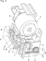
第4図は、キャッピング手段の退避状態を印字領域側から見た斜視図である。
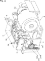
第5図は、キャッピング手段の退避状態を非印字領域側から見た斜視図である。
第6図は、ワイピング部材のワイピング状態を印字領域側から見た斜視図である。
第7図は、ワイピング部材のワイピング状態を非印字領域側から見た斜視図である。
第8図は、キャッピング手段のキャッピング状態を印字領域側から見た斜視図である。
第9図は、キャッピング手段のキャッピング状態を非印字領域側から見た斜視図である。
第10図は、キャッピング手段の退避状態を示す透視図である。
第11図は、ワイピング部材によるワイピング状態を示す透視図である。
第12図は、キャッピング手段のキャッピング状態を示す透視図である。
第13図は、ワイピング部材によるワイピング状態を示す透視図である。
第14図は、従来装置におけるキャッピング手段を示す説明図である。
発明を実施するための最良の形態
以下、本発明を実施するための最良の形態について説明する。なお、以下の説明は、本発明をインクジェット記録装置(液体噴射装置の一種)に適用した場合について行う。
図1に示すように、キャリッジ1は、ガイドロッド4に軸支されて紙送りローラ31の軸方向に移動可能に取り付けられている。そして、このキャリッジ1にはタイミングベルト3が接続されており、キャリッジ1はキャリッジモータ2によって往復移動される。即ち、キャリッジ1は、印刷データによるインク滴の吐出制御が可能な印字領域と、印刷データによるインク滴の吐出制御を行わない非印字領域(ホームポジションとも呼ばれる。)との間を、ガイドロッド4に沿って移動することができる。
なお、前記の印刷データは本発明の吐出データの一種であり、インク滴は本発明の液滴の一種である。また、前記の印字領域は本発明の吐出領域の一種であり、非印字領域は本発明の非吐出領域の一種である。
キャリッジ1の上面部はカートリッジ保持部として構成され、液体状のブラックインクを貯留したブラックインクカートリッジ7、及び、液体状のカラーインクを貯留したカラーインクカートリッジ8が着脱可能な状態で保持されている。
一方、キャリッジ1の下面部(記録用紙6に対向する側)には、記録ヘッド12が装着されている。この記録ヘッド12は、インク導入口から共通インク室及び圧力発生室を通ってノズル開口に至る一連のインク流路を有している。このインク流路における共通インク室よりも下流側の部分は複数設けられており、インク流路の下流端であるノズル開口はノズル形成面に開設されている(何れも図示せず)。そして、インクカートリッジ7,8からのインクは、前記インク導入口から導入されてインク流路内を満たす。
このインクの充填状態で、圧力発生室に配設した圧力発生素子(例えば、PZT等の電気機械変換素子やヒータ等の発熱素子)を作動させると、圧力発生室内に圧力変動が生じるので、ノズル開口からインク滴を吐出させることができる。
前記非印字領域には、キャッピング手段9が配置されている。このキャッピング手段9は、図3に示すように、上面が開放したトレイ形状のキャップ部材9a(単に「キャップ」,「ノズルキャップ」とも呼ばれる。)を備えている。そして、このキャッピング手段9は、前記記録ヘッド12が印字領域側からキャップ部材9aの直上に移動してきた時に退避位置からノズル形成面封止位置まで上昇する。これにより、前記記録ヘッド12のノズル形成面を前記キャップ部材9aによって封止してキャッピング状態にする。また、キャッピング手段9は、前記記録ヘッド12が直上から印字領域側へ移動する際にノズル形成面封止位置から退避位置まで下降し、キャップ部材9aによるキャッピング状態を解除する。
そして、このキャッピング手段9は、記録装置の休止期間中において、前記のキャッピング状態を維持し、前記ノズル開口を通じてインク溶媒が蒸発してしまう不具合を防止する。即ち、キャップ部材9aは、前記ノズル開口付近のインクの乾燥を防止する蓋体としても機能する。
また、このキャッピング手段9は、所謂フラッシング動作時におけるインク受けとしての機能も有する。即ち、この種の記録装置では、前記ノズル開口付近のインクの乾燥を防止すべく、印刷データに関係なくインク滴を吐出させることで、増粘インクを排出するフラッシング動作が行われている。そして、キャッピング手段9では、フラッシング動作によって吐出されたインク滴をキャップ部材9aの内側空間で受ける。
このキャッピング手段9に隣接して、インク吸引用のポンプユニット10が配置されている。このポンプユニット10は、記録用紙6を搬送するための紙送りモータ33(図2参照)を駆動源としており、この紙送りモータ33と共に本発明の吸引ポンプの一種として機能する。このポンプユニット10は、例えば、可撓性チューブをローラーで押し潰してしごくことでチューブ内の空気やインクを下流側に送る所謂チューブポンプユニットによって構成されている。そして、このポンプユニット10は、排液チューブ(図示せず)の途中に取り付けられている。この排液チューブは、一端がキャップ部材9aの内側空間(負圧空部)に連通され、他端が排液タンク(図示せず)に連通されている。このため、ポンプユニット10は、キャップ部材9aの内側空間を負圧化するための負圧化手段として機能する。
そして、前記したフラッシング動作時においてポンプユニット10を作動させると、キャップ部材9aに排出されたインクを排液タンクに送ることができる。また、キャップ部材9aでノズル形成面を封止した状態でポンプユニット10を作動させるとキャップ部材9aの内側空間が負圧化されるので、ノズル開口を通じて記録ヘッド12内のインクを吸引できる。これにより、記録ヘッド12内のインクをヘッド外部に排出させることができる。従って、このようなキャッピング手段9及びポンプユニット10は、クリーニング手段としての機能も兼ね備えているといえる。
なお、前記キャッピング手段9の上下方向の移動時にも、紙送りモータ33の駆動力が利用される。従って、キャッピング手段9とポンプユニット10とは駆動源を共用している関係にある。
また、図3に示すように、キャッピング手段9(キャップホルダ9b)における印字領域側の上端面には、ワイピング部材11が設けられている。このワイピング部材11は、前記記録ヘッド12のノズル形成面を払拭する部材である。そして、ワイピング部材11は、カム部材91(図5参照)の進行によってキャッピング手段9と共に上昇し、カム部材91の退避によってキャッピング手段9と共に下降するように構成されている。
次に、前記したキャッピング手段9およびこのキャッピング手段9の駆動手段(以下、キャッピング用駆動手段という。)について、図2〜図13に基づいて詳細に説明する。ここで、図2は、キャッピング用駆動手段の駆動側伝達装置30を示す断面図である。また、図3〜図9は、キャッピング用駆動手段の駆動側伝達装置30とその被駆動側伝達装置(従動側伝達装置)を示す斜視図である。また、図10〜図13は、キャッピング用駆動手段の中間伝達装置71を示す透視図である。
なお、キャッピング手段9は、少なくともキャップ部材9a、キャップホルダ9b、及び、保持フレーム9eを含んでいる。また、キャッピング用駆動手段とは、キャッピング手段9を上下鉛直方向に移動させるための手段であり、本実施形態では駆動源としての紙送りモータ33と、駆動側伝達装置30と、中間伝達装置71と、被駆動側伝達装置(案内装置)とを含んでいる。
先ず、図3〜図9に基づいて、キャッピング手段9について説明する。これらの図に示すように、キャッピング手段9は、前記記録ヘッド12のノズル形成面を封止し得るキャップ部材9a、及び、このキャップ部材9aを保持するキャップホルダ9bを有している。そして、このキャッピング手段9は、駆動側伝達装置30からの駆動力によって上昇位置(図8,図9)と下降位置(図4,図5)に移動し得るように構成されている。なお、上記の上昇位置はキャップ部材9aによるノズル形成面封止位置に相当し、下降位置はキャップ部材9aの退避位置に相当する。
前記キャップ部材9aは、平面から見て略矩形状の箱体、詳しくは、上面開放のトレイ状部材であり、全体が例えばエラストマーなどの弾性素材によって作製されている。そして、このキャップ部材9aは、例えば二色成形(ダブルモールド)により、前記キャップホルダ9bに一体に形成されている。なお、これに限らず、キャップ部材9aとキャップホルダ9bとを別個に作製した後に、これらの部材を接合してもよい。そして、本実施形態のように、キャップ部材9aとキャップホルダ9bとを一体に形成することにより、キャップ部材9aがキャップホルダ9bから離脱してしまう不具合を防止でき、装置の信頼性を長期間に亘って維持できる。
この前記キャップ部材9aの内側空間にはインク吸収シート(図示せず)が収容され、前記記録ヘッド12からのインクを吸収して一時的に保持し得るように構成されている。そして、前記したように、キャップ部材9aの内部空間は、可撓性を有する排液チューブ(図示せず)を通じて排液タンクに連通しており、この排液チューブの途中に前記ポンプユニット10が配設されている。
一方、前記キャップホルダ9bは平面から見て略矩形状の箱体からなり、前記キャップ部材9aの素材であるエラストマーよりも硬い素材(樹脂)によって作製されている。また、このキャップホルダ9bの印字領域側端部には、長尺縁部の両側に位置し、かつ上方に向けて少し拡開させた状態で突出する一対のキャッピングガイド9dが一体に設けられている。
また、前記キャッピング手段9は、前記キャップホルダ9bを保持する断面ほぼコ字状の保持フレーム9e(保持部材の一種)を有している。この保持フレーム9eの両側部には、前記記録ヘッド12の移動方向(本実施形態では水平方向)に開口する保持孔(図示せず)がそれぞれ設けられている。これらの保持孔には支持軸9cが回転可能に支持されている。即ち、保持フレーム9eはこの支持軸9cによって保持されている。従って、キャップ部材9aは、キャップホルダ9b及び保持フレーム9eを介して間接的に支持軸9cに保持されているといえる。
そして、この支持軸9cは、前記記録ヘッド12の移動方向に延在する丸軸によって形成されている。なお、上記の保持部材としては、保持フレーム9eに限らず、キャップ部材9aを保持し、支持軸9cを回転可能に支持できれば、この形態に限定されるものではない。
また、前記保持フレーム9eよりも外側には、この保持フレーム9eを囲うように固定フレーム21が近接状態で配設されている。この固定フレーム21は、平面から見て略コ字状の板状部材によって構成されている。この固定フレーム21の両側部には上下鉛直方向に延在する長孔21aが形成され、前記支持軸9cの両端部は、これらの長孔21aに挿通されている。また、固定フレーム21の両側部には、この長孔21aに沿って上下方向に延在するラック102a,103a(図4,図5参照)が配設されている。
次に、キャッピング用駆動手段について説明する。なお、本実施形態におけるキャッピング用駆動手段は、上記したように、駆動源及び駆動側伝達装置30と、中間伝達装置71と、被駆動側伝達装置とから構成されているため、「駆動側伝達装置」と「中間伝達装置」と「被駆動側伝達装置」とに分けて説明する。
まず、「駆動側伝達装置」について説明する。図2に示すように、駆動側伝達装置30は、給排紙機構、ポンプユニット10、及び、キャッピング手段9についての共通の駆動力伝達手段として機能する。そして、この駆動側伝達装置30では、キャッピング手段9を移動させるにあたり、本発明の駆動源の一種である紙送りモータ33からの駆動力(回転力)を中間伝達装置71に伝達する。
そして、この駆動側伝達装置30は紙送りローラ31を有している。この紙送りローラ31の一端には歯車32が配置され、紙送りモータ33の軸上に配置されたピニオン34から中間歯車35を介して駆動されるように構成されている。また、給紙ローラ駆動軸36の一端には歯車37が配置され、クラッチ機構を構成する移動歯車38を介して前記歯車32と噛合してカットシートフィーダ(図示せず)に動力を伝達する。この伝達された動力によって、記録用紙6の給紙(ローディング)が行われる。
一方、紙送りモータ33からの動力は、ピニオン34,中間歯車39および排紙ローラ41上の排紙ローラ歯車40に伝達される。さらに、この排紙ローラ歯車40からの動力は、同じく排紙ローラ41上の歯車42,中間歯車44,従動歯車45を介して駆動軸43に伝達される。そして、動力が駆動軸43に伝達されると、ポンプユニット10が駆動される。即ち、紙送りモータ33からの動力は、排紙ローラ41及び駆動軸43を介して中間伝達装置71に伝達される。
なお、前記ポンプユニット10は、図3に示すように、固定ベース(取付用ベース)46に対してポンプフレーム53を取り付けた構成である。そして、前記駆動軸43は、これらの固定ベース46およびポンプフレーム53に回転自在に軸支されている。また、前記固定ベース46には、カム部材91の進退方向(移動方向)に延在するガイド孔46aが設けられている。
次に、「中間伝達装置71」について説明する。図10〜図13に示すように、中間伝達装置71は、遊星歯車機構81およびカム部材91を有する。そして、この中間伝達装置71は、前記固定ベース46と前記ポンプフレーム53との間に配設されて、前記駆動側伝達装置30からの駆動力を被駆動側伝達装置に伝達する。
前記遊星歯車機構81は、太陽歯車72を有する前記駆動軸(ポンプ軸)48と、この駆動軸43に回転可能な状態で取り付けられる駆動レバー73および保持レバー74とを備えている。
前記駆動レバー73は、前記駆動軸43が挿通する円環状の基部73aおよびこの基部73aよりも外側に突出する舌片状のレバー部73bを有する。この駆動レバー73は、前記保持レバー74におけるポンプユニット10とは反対側の位置に配設され、かつ前記駆動軸43に対して所定の回動ストローク内で回動可能に支持されている。この駆動レバー73のレバー部73bには、ポンプ側(水平方向)に突出する円柱状の駆動ピン75が一体に設けられている。また、駆動レバー73の基部73aには、前記レバー部73bと反対側に突出し、立ち上がり壁76aを外周縁に有する平面扇形状の延在部76が一体に設けられている。そして、この延在部76の立ち上がり壁76aには、円周方向に沿って内歯77が設けられている。
前記保持レバー74は、前記駆動軸43が挿通する円環状の基部(図示せず)およびこの基部の放射方向に突出する矩形片状のレバー部74b,74cを有する。そして、この保持レバー74は、前記駆動軸43に対して回動方向の二位置間で回動可能に支持されている。前記レバー部74bには、ストッパ係合部74C,74Dが設けられている。これらのストッパ係合部74C,74Dは、ポンプフレーム円周方向に所定の間隔をもって並列する両ストッパ53c,53dに対して係合可能な部位である。また、前記レバー部74cには、前記太陽歯車72に噛合した状態で遊星歯車78が回転可能に保持されている。そして、この遊星歯車78は、前記駆動レバー73の内歯77に噛合可能に構成されている。
前記両レバー部74b,74cのうち少なくともレバー部74cは、前記各ストッパ係合部74C,74Dが前記各ストッパ53c,53dに係合している状態において、前記駆動レバー73の回動による外力を受けて弾性変形し得るよう、弾性ロッド部として構成されている。これにより、保持レバー74が回動停止し、かつ駆動レバー73が回動した場合において、遊星歯車78と内歯77との噛合に伴う衝撃が吸収される。
一方、前記カム部材91は、図10〜図13に示すように、前記遊星歯車機構81(駆動ピン75)に連結され、かつ、進退可能な状態で前記固定ベース46(図3)に配設されている。このカム部材91には、前記ガイド孔46a内を摺動可能な凸部91aが設けられている。これにより、カム部材91は、記録ヘッド12の移動方向と直角な水平方向に移動可能に構成されている。また、前記カム部材91には、図5,図7,図9および図10〜図13に示すように、第一長孔92および第二長孔93が板厚方向を貫通した状態で設けられている。
前記第一長孔92は、水平部92a〜92cおよび傾斜部92d,92eを有し、前記支持軸9cを案内するように構成されている。前記水平部92aは前記第一長孔92の低所部に、前記水平部92bは前記第一長孔92の高所部に配置されている。また、前記水平部92cは前記第一長孔92の中間部(即ち、高さ方向において水平部92a,92bの間)に配置されている。これらの水平部92a〜92cは、前記カム部材91の進行方向と平行な孔部、即ち、カム部材91の進行位置から退避位置に向かって水平方向に延在する孔部によって形成されている。そして、前記水平部92aは前記カム部材91の退避状態(キャッピングの解除状態)において前記支持軸9cを保持し、前記水平部92bは進行状態(キャッピング状態)において前記支持軸9cを保持する。また、前記水平部92cは、ワイピング状態において前記支持軸9cを保持する。
前記傾斜部92dは前記両水平部92a,92cの間に設けられ、前記傾斜部92eは前記両水平部92c,92bの間に設けられている。これら傾斜部92d,92eは、前記カム部材91の進行位置から退避位置に向かって上る勾配をもつ孔部によって形成されている。そして、前記傾斜部92dはワイピング時やキャッピング時において前記支持軸9cに対して退避位置からワイピング位置への昇降力を付与する。また、前記傾斜部92eはキャッピング時において前記支持軸9cに対してワイピング位置からキャッピング位置への昇降力を付与する。
前記第二長孔93は、前記第一長孔92よりもポンプユニット10側に配置されている。そして、この第二長孔93は上下方向に延在する孔部であり、前記駆動ピン75を上下方向に案内する。
次に「被駆動側伝達装置」について説明する。図4〜図9に示すように、前記中間伝達装置71に連結された被駆動側伝達装置は、一対のラック−ピニオン機構102,103および前記支持軸9cを有している。一方のラック−ピニオン機構102は前記固定フレーム21の一方の側面(非印字領域側部)に、他方のラック−ピニオン機構103は前記固定フレーム21の他方の側面(印字領域側部)にそれぞれ配設されている。これら両ラック−ピニオン機構102,103は、前記固定フレーム21において左右対称の位置に配置されている。
上記の支持軸9cは、前記両ラック−ピニオン機構102,103間に配設されている。また、この支持軸9cの非印字側端部は前記ラック−ピニオン機構102の一部を構成するピニオン102bに挿通して固着されており、この挿通端部は前記カム部材91の第一長孔92内に転動可能に保持されている。これにより、カム部材91の進退によって支持軸9cが第一長孔92内で転動する。従って、この転動力(回転力)は、一方のラック−ピニオン機構102から他方のラック−ピニオン機構103に伝達される。
前記ラック−ピニオン機構102は、ラック102aおよびピニオン102bを有している。前記ラック102aは、上下鉛直方向に延在し、前記固定フレーム21における非印字領域側の端部に突設されている。前記ピニオン102bは、前記支持軸9cの非印字領域端部に固着され、前記ラック102aに噛合している。一方、前記ラック−ピニオン機構103は、ラック103aおよびピニオン103bを有している。このラック−ピニオン機構103では、前記ラック−ピニオン機構102(即ち、支持軸9c)からの回転力を前記保持フレーム9eの印字領域側端部で受け、この回転力によってピニオン103bがラック103aに沿って転動する。なお、このラック−ピニオン機構103のラック103a,ピニオン103bは、前記ラック−ピニオン機構102のラック102a,ピニオン10bと同一の構成であるため、その詳細な説明は省略する。
また、前記支持軸9cは、前記したように保持フレーム9e(保持孔)に回転可能に支持されるとともに、前記固定フレーム21の長孔21a内において、回転可能かつ昇降可能な状態で挿通保持されている。そのため、支持軸9cがカム部材91からの昇降力を受けて前記支持軸9cが固定フレーム21の長孔21a内を昇降する際において、この支持軸9は前記ラック−ピニオン機構102,103によって案内される。そして、前記キャップ部材9aの封止面と前記記録ヘッド12のノズル形成面とが平行となる状態を維持したままキャップホルダ9b(キャップ部材9a)は昇降される。
以上の構成において、図4,図5および図10に示すリセット(退避)状態から、太陽歯車72(駆動軸43)が駆動側伝達装置30(紙送りモータ33)からの駆動力を受けて正方向(反時計方向)に回動を開始すると、この回動力が遊星歯車78を介して保持レバー74に伝達され、保持レバー74が反時計方向(図10において矢印e方向)に回動する。そして、保持レバー74が矢印e方向に回動すると、ストッパ係合部74Dがストッパ53dから離間する。
なお、太陽歯車72の回転開始状態においては、遊星歯車78と内歯77との噛合が解除されているため、駆動レバー73が太陽歯車72からの駆動力を受けず、図10に示すように回動開始位置に停止したままである。また、駆動ピン75および支持軸9cは、それぞれ第二長孔93の始端部(下端部)と第一長孔92の水平部92aに位置付けられている。
そして、太陽歯車72がなおも反時計方向に回転すると、保持レバー74が反時計方向(矢印e方向)にさらに回動する。この場合、遊星歯車78は、内歯77に噛合して時計方向に回転しながら内歯77上を反時計方向に移動する。このため、ストッパ係合部74Cがストッパ53cに係合するまでは、駆動レバー73が時計方向に(カム部材91を進行させる方向)に回動することはない。そして、保持レバー74がさらに回動すると、ストッパ係合部74Cがストッパ53cに係合するので、保持レバー74は一方側の回動停止位置にて停止する。そして、この状態、すなわちストッパ係合部74Cがストッパ53cに係合した状態のまま、太陽歯車72がさらに反時計方向に回転すると、遊星歯車78が時計方向に回転し、駆動レバー73が時計方向への回動を開始する。
この場合、太陽歯車72からの回動力が遊星歯車78を介して保持レバー74に伝達されるが、レバー部74bのストッパ係合部74Cがストッパ53cに係合しているため、保持レバー74が反時計方向(矢印e方向)に回動することはない。このため、太陽歯車72からの回転力が遊星歯車78を介して保持レバー74に伝達されると、レバー部74cがレバー部74bに接近するような方向に撓む。
そして、太陽歯車72がさらに反時計方向に回転すると、遊星歯車78がさらに時計方向に回転し、駆動レバー73も時計方向に回動する。この場合、駆動レバー73が時計方向に回動すると、レバー部73bも同方向に回動するため、この回動力をカム部材91が進行力として受け、図10に示す退避位置から進行位置に向かって矢印g方向に移動する。このカム部材91の移動に伴い、支持軸9cがカム部材91、即ち、第一長孔92の傾斜部92dから回転力と上昇力とを受ける。このため、支持軸9cが傾斜部92d上を反時計方向に回転しながら上昇するとともに、ピニオン102b,103bがラック102a,103aに沿って上方に転動する。この転動に伴い、ワイピング部材11が保持フレーム9eと共に記録ヘッド12の移動経路外から移動経路内のワイピング位置に向かって進行(鉛直上方に移動)する。
そして、図6,図7および図11に示すように、支持軸9cが傾斜部92dから水平部92cに乗り上げると、ワイピング部材11がワイピング位置に到達する。このワイピング位置で記録ヘッド12が非印字領域側へ移動されるとノズル形成面が払拭される。なお、ワイピング部材11が図10に示す退避位置からワイピング位置に上昇すると、駆動ピン75が第二長孔93の始端部(下端部)から移動して終端部(上端部)に位置付けられる。
この後、太陽歯車72がさらに反時計方向に回転すると、遊星歯車78がさらに時計方向に回転し、これに伴い駆動レバー73も時計方向(矢印f方向)に回動する。この場合、駆動レバー73が時計方向に回動すると、レバー部73bも同方向に回動するため、カム部材91が図11に示す位置から進行位置に向かって矢印g方向に移動する。このカム部材91の移動に伴い、支持軸9cがカム部材91、即ち、第一長孔92の傾斜部92eから上昇力を受ける。
このため、支持軸9cが傾斜部92e上を時計方向に回転しながら上昇するとともに、ピニオン102b,103bがラック102a,103aに沿って案内されながら鉛直上方に転動する。この転動に伴い、キャッピング手段9がワイピング位置からキャッピング位置(ノズル形成面封止位置)に向かって進行、即ち上昇する。そして、図8,図9および図12に示すように、支持軸9cが傾斜部92eから水平部92bに乗り上げると、キャップ部材9aがキャッピング位置に到達し、キャッピング位置における記録ヘッド12のノズル形成面がキャッピング手段9(キャップ部材9a)によって封止される。
なお、キャッピング手段9がキャッピング位置に到達すると、図12に示すように保持レバー74のレバー部74cが弾性復帰し、遊星歯車78と内歯77との噛合が解除される。このため、駆動レバー73が太陽歯車72からの駆動力を受けず、回動終了位置に配置される。また、駆動ピン75が第二長孔93の終端部(上端部)から移動して始端部(下端部)に位置付けられる。
一方、図8,図9および図12に示すセット状態から、太陽歯車72(駆動軸43)が駆動側伝達装置30(紙送りモータ33)からの駆動力を受けて逆方向(時計方向)に回動を開始すると、この回動力が遊星歯車78を介して保持レバー74に伝達され、保持レバー74が時計方向(図12において矢印f方向)に回動する。この場合、保持レバー74が矢印f方向に回動すると、ストッパ係合部74Cがストッパ53cから離間する。
なお、太陽歯車72の回転開始状態においては、遊星歯車78と内歯77との噛合が解除されているため、駆動レバー73が太陽歯車72からの駆動力を受けず、図12に示すように回動終了位置に停止したままである。また、駆動ピン75および支持軸9cがそれぞれ第二長孔93の始端部(下端部)と第一長孔92の水平部92bに位置付けられている。
そして、太陽歯車72がなおも時計方向に回転すると、保持レバー74が時計方向(矢印f方向)にさらに回動する。この保持レバー74の回動により、遊星歯車78が内歯77に噛合して反時計方向に回転しながら内歯77上を時計方向に移動する。このため、ストッパ係合部74Dがストッパ53dに係合するまでは、駆動レバー73が反時計方向(カム部材91を退避させる方向)に回動することはない。
そして、保持レバー74がさらに回動すると、ストッパ係合部74Dがストッパ53dに係合するので、保持レバー74は他方側の回動停止位置にて停止する。この状態、すなわちストッパ係合部74Dがストッパ53dに係合した状態のまま、太陽歯車72がさらに時計方向に回転すると、遊星歯車78が反時計方向に回転し、駆動レバー73が反時計方向への回動を開始する。この場合、太陽歯車72からの回動力が遊星歯車78を介して保持レバー74に伝達されるが、レバー部74bのストッパ74Dがストッパ53dに係合しているため、保持レバー74が時計方向(矢印f方向)に回動することはない。このため、太陽歯車72からの回動力が遊星歯車78を介して保持レバー74に伝達されると、レバー部74cがレバー部74bから離間するような方向に撓む。
そして、太陽歯車72がさらに時計方向に回転すると、遊星歯車78がさらに反時計方向に回転し、駆動レバー73も反時計方向に回動する。この場合、レバー部73bも同方向に回動するため、この回動力をカム部材91が退避力として受け、図12に示すキャッピング位置(セット位置)から退避位置に向かって矢印h方向に移動する。このカム部材91の移動に伴い、支持軸9cが重力によって下降力を受ける。
このため、支持軸9cが傾斜部92e上を時計方向に回転しながら下降するとともに、ピニオン102b,103bがラック102a,103aに沿って案内されながら鉛直下方に転動する。この転動に伴い、ワイピング部材11がキャッピング手段9と共に記録ヘッド12の移動経路内から移動経路外にワイピング位置に向かって退避、即ち下降し、キャッピング位置における記録ヘッド12のノズル形成面の封止状態が解除される。そして、図6,図7および図13に示すように、ワイピング部材11がキャッピング手段9と共にさらに下降し、支持軸9cが傾斜部92eから水平部92cに乗り移ると、ワイピング部材11がワイピング位置に到達する。この状態で、記録ヘッド12が印字領域側へ移動制御されると、ワイピング部材11によってノズル形成面が払拭される。
なお、ワイピング部材11が図12に示す進行位置からワイピング位置に下降すると、駆動ピン75が第二長孔93の始端部(下端部)から移動して終端部(上端部)に位置付けられる。
この後、太陽歯車72がさらに時計方向に回転すると、遊星歯車78がさらに反時計方向に回転し、こ駆動レバー73も反時計方向(矢印e方向)に回動する。この場合、駆動レバー73が反時計方向に回動すると、レバー部73bが同方向に回動するため、カム部材91が図13に示す位置から退避位置に向かって矢印h方向に移動し、この移動に伴い支持軸9cが重力によって下降力を受ける。
このため、図4,図5および図10に示すように、支持軸9cが傾斜部92d上を反時計方向に回転しながら下降するとともに、ピニオン102b,103bがラック102a,103aに沿って案内されながら鉛直下方に転動する。この転動に伴い、キャッピング手段9が図13に示す位置から退避位置(リセット位置)に向かって退避(下降)する。そして、支持軸9cが傾斜部92dから水平部92aに乗り移ると、キャッピング手段9が退避位置に到達する。
なお、キャッピング手段9がリセット位置に下降すると、図10に示すように保持レバー74のレバー部74cが弾性復帰し、遊星歯車78と内歯77との噛合が解除される。このため、駆動レバー73が太陽歯車72からの駆動力を受けず、回動終了位置に配置される。
また、駆動ピン75が第二長孔93の終端部(上端部)から移動して始端部(下端部)に位置付けられる。したがって、本実施形態においては、カム部材91の進行によるキャッピング手段9の上昇(鉛直上方への移動)によって記録ヘッド12のノズル形成面が封止される。一方、カム部材91の退避によるキャッピング手段9の下降(鉛直下方への移動)によって記録ヘッド12のノズル形成面の封止状態が解除される。
これにより、キャッピング手段9のセット・リセット動作が該キャッピング手段9による上下鉛直方向の移動でなされる。このため、キャッピング手段9の移動領域を可及的に縮小することができ、装置全体の小型化を図ることができる。
また、本実施形態において、支持軸9cを鉛直方向に案内するラック−ピニオン機構102,103がキャッピング手段9の両側に配設されているので、キャップ部材9aの封止面と記録ヘッド12のノズル形成面とが平行になるようにキャッピング手段9を昇降させることができる。
さらに、本実施形態において、ワイピング部材11がキャップホルダ9bに設けられているので、キャップ9aおよびキャップホルダ9bとワイピング部材11とをエラストマー等で一体に成形することができる。このため、コストの低廉化を図ることができる。
さらにまた、本実施形態において、キャップ9aとワイピング部材11とが一体に成形可能であることは、これら各部材9a,11を互いに近接させることができることを意味する。このため、インク飛散による汚染領域を縮小することができる。
この他、本実施形態においては、駆動軸43がポンプユニット10のポンプ駆動軸によって構成されている。これにより、ポンプ駆動軸の回転力を、キャッピング手段9を上下方向に移動させるための駆動力として用いることができる。その結果、部品点数を削減することができる。
また、本実施形態においては、支持軸9cを案内する第二長孔92に水平部92b,92cが設けられているので、これら水平部92b,92cにて支持軸9cを保持することでワイピング動作およびキャッピング動作が可能となる。このため、キャップ部材9aの高さが定まり、ワイピング動作およびキャッピング動作を確実に行うことができる。
なお、本実施形態においては、カム部材91に進退力を付与するための伝達機構として遊星歯車機構81を例に挙げて説明したが、本発明はこれに限定されない。即ち、他の進退力付与機構を用いてもよい。この場合、駆動側伝達装置30から被駆動側伝達装置への駆動力伝達が進退力付与機構およびカム部材91(共に図示せず)を介して行われる。
産業上の利用の可能性
本発明は、上記したように、インク滴を吐出して印刷記録媒体上に文字や画像を記録可能な画像記録装置に適用することができる。この他に、本発明は、フィルタ基材上に色材を吐出してカラーフィルタを製造するフィルタ製造装置、液晶や液状の電極材等をディスプレイ基体表面に吐出して液晶ディスプレイやELディスプレイ、FED(面発光ディスプレイ)等の各種ディスプレイを製造するディスプレイ製造装置にも適用できる。さらに、本発明は、バイオチップの製造に用いられるバイオチップ製造装置、及び、極く少量の液体を精度良く供給するマイクロピペットにも適用できる。
符号の説明
1 キャリッジ
2 キヤリッジモータ
3 タイミングベルト
4 ガイドロッド
6 記録用紙
7 ブラックインクカートリッジ
8 カラーインクカートリッジ
9 キヤツピング手段
9a キャップ部材
9b キャップホルダ
9d キャッピングガイド
9e 保持フレーム
9c 支持軸
10 ポンプユニット
11 ワイピング部材
12 記録ヘッド
21 固定フレーム
21a 長孔
30 駆動側伝達装置
31 紙送りローラ
32 歯車
33 紙送りモータ
34 ピニオン
35 中間歯車
36 給紙ローラ駆動軸
37 歯車
38 移動歯車
39 中間歯車
40 排紙ローラ歯車
41 排紙ローラ
42 歯車
43 駆動軸
44 中間歯車
45 従動歯車
46 固定ベース
46a ガイド孔
53 ポンプフレーム
53c ストッパ
53d ストッパ
71 中間伝達装置
72 太陽歯車
73 駆動レバー
73a 基部
73b レバー部
74 保持レバー
74b レバー部
74c レバー部
74C ストッパ係合部
74D ストッパ係合部
75 駆動ピン
76 延在部
76a 立ち上がり壁
77 内歯
78 遊星歯車
81 遊星歯車機構
91 カム部材
91a 凸部
92 第一長孔
92a 水平部
92b 水平部
92c 水平部
92d 傾斜部
92e 傾斜部
93 第二長孔
102 ラック−ピニオン機構
102a ラック
102b ピニオン
103 ラック−ピニオン機構
103a ラック
103b ピニオン
201 キャップ部材
202 キャップホルダ
203 第1のラック
204 可動体
205 スライダ
206 可動体の本体部
207 スプリング
208 ギア
209 支持体
210 スプリング
211 第2のラック
212 記録ヘッド
213 キヤリッジTechnical field
The present invention relates to a liquid ejecting apparatus including a recovery mechanism that recovers a discharge function by sucking and discharging liquid from a liquid ejecting head.
Background art
Background art relating to the present invention will be described by taking an ink jet recording apparatus which is a kind of liquid ejecting apparatus as an example. This ink jet recording apparatus has a relatively low noise during printing and can record extremely small dots at a high density. Therefore, the ink jet recording apparatus has been used for various types of printing including color printing.
In this ink jet recording apparatus, liquid ink is ejected as droplets from nozzle openings. Since the nozzle opening is released, the ink solvent gradually evaporates through the nozzle opening when the recording apparatus is not used. If the evaporation amount of the ink solvent is excessively large, the viscosity of the ink in the vicinity of the nozzle opening is increased, resulting in clogging. Further, bubbles may be mixed into the recording head through the nozzle openings. In this case, the flow of ink may be hindered by the mixed bubbles, which may cause printing failure.
In order to prevent such problems, the ink jet recording apparatus is provided with a recovery mechanism for forcibly discharging the ink in the recording head through the nozzle openings. This recovery mechanism generally includes a cap member that includes a negative pressure air portion, a suction pump that communicates with the negative pressure air portion, and a drive mechanism that moves the cap member. In the recovery operation by the recovery mechanism, first, the nozzle forming surface (that is, the nozzle opening forming surface; the same applies hereinafter) is sealed with the cap member, and then the negative pressure pump is operated. By the operation of the negative pressure pump, the negative pressure space is made negative, and the ink in the recording head is sucked through the nozzle openings.
Various configurations have been proposed as the drive mechanism, and one of them is a configuration using a rack and a gear (for example, Patent Document 1). In this configuration, as shown in FIG. 14, the slider is provided with a cap holder 202 provided with a cap member (nozzle cap) 201 on the front end face and a
In this configuration, when the carriage (carrier) 213 including the
In this configuration, since the movement of the
The above-mentioned Patent Document 1 is Japanese Patent Laid-Open No. 5-69551.
Disclosure of the invention
However, in the conventional configuration described above, it is necessary to secure a space for the
The present invention has been made in view of such circumstances, and an object of the present invention is to reduce the space for moving the cap member as much as possible, thereby reducing the size of the entire apparatus, and the cap. It is to further increase the capping accuracy such as the position of the member and the adhesion of the cap member.
In order to achieve this object, the present invention attaches a discharge area that can be controlled to discharge droplets based on discharge data to a non-discharge area that is not controlled to discharge droplets based on discharge data. A liquid ejecting head capable of ejecting liquid droplets from a nozzle opening established on a nozzle forming surface;
A capping unit including a cap member disposed in the non-ejection region and capable of sealing the nozzle forming surface;
A liquid ejecting apparatus comprising: a driving unit configured to move the cap member in a vertical direction between a nozzle forming surface sealing position of the liquid ejecting head and a retracted position set below the nozzle forming surface sealing position. In
A fixed frame disposed below the head movement path in the non-ejection region and having a guide elongated hole extending in the vertical direction;
The support member extends from one side and the opposite side of the cap member to support the cap member, and has a support shaft inserted through the guide slot.
The drive means includes racks disposed on both sides of the fixed frame, and pinions fixed to both ends of the support shaft, and a rack-pinion mechanism that guides the support shaft in the vertical direction; A cam member that slides the support shaft through the cam groove and moves the support shaft in the vertical direction;
The support shaft is slid by the cam groove so as to be moved in the vertical direction along the guide long hole to perform capping by the cap member.
In this configuration, when the drive unit is driven to raise the cap member, the nozzle forming surface of the recording head is sealed by the cap member, and a capping state is obtained. On the other hand, when the cap member is lowered, the cap member is separated from the nozzle forming surface, and the capping state is released. At this time, since the moving direction of the cap member is the vertical direction, the space secured for the movement of the cap member can be reduced as much as possible, and the entire apparatus can be downsized.
Further, the cap member supported by the support shaft is moved by a rack-pinion mechanism comprising racks disposed on both sides of the fixed frame and pinions fixed to both ends of the support shaft that supports the capping member. Therefore, it is difficult for the cap member to tilt during movement. Therefore, the nozzle forming surface can be reliably sealed with high accuracy by the cap member.
[Brief description of the drawings]
FIG. 1 is a schematic diagram showing an outline of the overall configuration of an ink jet recording apparatus.
FIG. 2 is a sectional view showing a drive-side transmission device of the capping drive means.
FIG. 3 is a perspective view showing a drive-side transmission device and a driven-side transmission device of the capping drive means.
FIG. 4 is a perspective view of the retracted state of the capping means as viewed from the print region side.
FIG. 5 is a perspective view of the retracted state of the capping means as seen from the non-printing area side.
FIG. 6 is a perspective view of the wiping state of the wiping member as viewed from the print region side.
FIG. 7 is a perspective view of the wiping state of the wiping member as viewed from the non-printing area side.
FIG. 8 is a perspective view of a capping state of the capping means as viewed from the print region side.
FIG. 9 is a perspective view of the capping state of the capping means as viewed from the non-printing area side.
FIG. 10 is a perspective view showing the retracted state of the capping means.
FIG. 11 is a perspective view showing a wiping state by a wiping member.
FIG. 12 is a perspective view showing a capping state of the capping means.
FIG. 13 is a perspective view showing a wiping state by a wiping member.
FIG. 14 is an explanatory view showing capping means in the conventional apparatus.
BEST MODE FOR CARRYING OUT THE INVENTION
Hereinafter, the best mode for carrying out the present invention will be described. In the following description, the present invention is applied to an ink jet recording apparatus (a kind of liquid ejecting apparatus).
As shown in FIG. 1, the carriage 1 is attached to the guide rod 4 so as to be movable in the axial direction of the
The print data is a type of ejection data according to the present invention, and the ink droplet is a type of droplet according to the present invention. The printing area is a kind of ejection area of the present invention, and the non-printing area is a kind of non-ejection area of the present invention.
The upper surface portion of the carriage 1 is configured as a cartridge holding portion, and the black ink cartridge 7 storing liquid black ink and the color ink cartridge 8 storing liquid color ink are held in a detachable state. .
On the other hand, a
When a pressure generating element (for example, an electromechanical conversion element such as PZT or a heating element such as a heater) disposed in the pressure generating chamber is operated in this ink filling state, a pressure fluctuation occurs in the pressure generating chamber. Ink droplets can be ejected from the openings.
Capping means 9 is disposed in the non-printing area. As shown in FIG. 3, the capping means 9 includes a tray-shaped
The
The capping means 9 also has a function as an ink receiver during a so-called flushing operation. That is, in this type of recording apparatus, a flushing operation for discharging thickened ink is performed by ejecting ink droplets irrespective of print data in order to prevent drying of ink near the nozzle opening. The capping means 9 receives the ink droplets ejected by the flushing operation in the inner space of the
An ink
When the
The driving force of the
Further, as shown in FIG. 3, a wiping member 11 is provided on the upper end surface of the capping unit 9 (
Next, the
The capping means 9 includes at least a
First, the capping means 9 will be described with reference to FIGS. As shown in these drawings, the
The
An ink absorbing sheet (not shown) is accommodated in the inner space of the
On the other hand, the
The capping means 9 has a holding frame 9e (a kind of holding member) having a substantially U-shaped cross section for holding the
The
Further, a fixed
Next, the capping driving means will be described. As described above, the capping drive means in the present embodiment is composed of the drive source and drive
First, the “drive-side transmission device” will be described. As shown in FIG. 2, the drive-
The drive-
On the other hand, the power from the
The
Next, the “
The
The
The holding
At least the
On the other hand, as shown in FIGS. 10 to 13, the
The first
The
The second
Next, the “driven transmission device” will be described. As shown in FIGS. 4 to 9, the driven transmission device connected to the
The
The rack-
Further, the
In the above configuration, the sun gear 72 (drive shaft 43) receives the driving force from the drive side transmission device 30 (paper feed motor 33) in the reset (retracted) state shown in FIGS. When rotation in the direction (counterclockwise) is started, this turning force is transmitted to the holding
In addition, in the rotation start state of the
When the
In this case, the rotational force from the
When the
As shown in FIGS. 6, 7 and 11, when the
Thereafter, when the
Therefore, the
When the capping means 9 reaches the capping position, the
On the other hand, the sun gear 72 (drive shaft 43) receives the driving force from the drive-side transmission device 30 (paper feed motor 33) in the reverse direction (clockwise) from the set state shown in FIGS. When the rotation starts, this turning force is transmitted to the holding
In the state where the
When the
When the holding
When the
Therefore, the
When the wiping member 11 is lowered from the advancing position shown in FIG. 12 to the wiping position, the
Thereafter, when the
Therefore, as shown in FIGS. 4, 5 and 10, the
When the capping means 9 is lowered to the reset position, the
Further, the
As a result, the set / reset operation of the
In the present embodiment, since the rack-
Furthermore, in this embodiment, since the wiping member 11 is provided in the
Furthermore, in the present embodiment, that the
In addition, in this embodiment, the
In the present embodiment, since the
In the present embodiment, the
Industrial applicability
As described above, the present invention can be applied to an image recording apparatus capable of recording characters and images on a print recording medium by ejecting ink droplets. In addition, the present invention provides a filter manufacturing apparatus for manufacturing a color filter by discharging a color material on a filter substrate, a liquid crystal display, an EL display, and an FED by discharging a liquid crystal or liquid electrode material to the display substrate surface. The present invention can also be applied to a display manufacturing apparatus that manufactures various displays such as (surface emitting display). Furthermore, the present invention can be applied to a biochip manufacturing apparatus used for manufacturing a biochip and a micropipette that supplies an extremely small amount of liquid with high accuracy.
Explanation of symbols
1 Carriage
2 Carriage motor
3 Timing belt
4 Guide rod
6 Recording paper
7 Black ink cartridge
8 Color ink cartridge
9 Capturing means
9a Cap member
9b Cap holder
9d capping guide
9e Holding frame
9c Support shaft
10 Pump unit
11 Wiping members
12 Recording head
21 Fixed frame
21a long hole
30 Drive-side transmission device
31 Paper feed roller
32 gears
33 Paper feed motor
34 Pinion
35 Intermediate gear
36 Feed roller drive shaft
37 gears
38 Moving gear
39 Intermediate gear
40 Paper discharge roller gear
41 Paper discharge roller
42 Gear
43 Drive shaft
44 Intermediate gear
45 Driven gear
46 Fixed base
46a Guide hole
53 Pump frame
53c stopper
53d stopper
71 Intermediate transmission device
72 Sun Gear
73 Drive lever
73a base
73b Lever part
74 Holding lever
74b Lever part
74c Lever part
74C Stopper engaging part
74D Stopper engaging part
75 Drive pin
76 Extension
76a Rising wall
77 internal teeth
78 Planetary Gear
81 Planetary gear mechanism
91 Cam member
91a Convex
92 1st slot
92a Horizontal part
92b Horizontal part
92c Horizontal part
92d slope
92e inclined part
93 Second slot
102 rack-pinion mechanism
102a rack
102b pinion
103 rack-pinion mechanism
103a rack
103b Pinion
201 Cap member
202 Cap holder
203 first rack
204 Movable body
205 slider
206 Main body of movable body
207 Spring
208 Gear
209 Support
210 Spring
211 Second rack
212 Recording head
213 Carriage
Claims (6)
前記非吐出領域に配設され、前記ノズル形成面を封止可能なキャップ部材を含むキャッピング手段と、
前記キャップ部材を、前記液体噴射ヘッドのノズル形成面封止位置と該ノズル形成面封止位置の下方に設定された退避位置との間で上下方向に移動させる駆動手段とを備えた液体噴射装置において、
前記非吐出領域におけるヘッド移動経路の下方に配設され、上下方向に延在するガイド長孔を有する固定フレームと、
前記キャップ部材の一方側及び反対側から延出して該キャップ部材を支持すると共に、前記ガイド長孔に挿通される支持軸とを有し、
前記駆動手段は、前記固定フレームの両側部に配設されたラック、及び、前記支持軸の両端部に固着されたピニオンを含み、前記支持軸を上下方向に案内するラック−ピニオン機構と、前記支持軸をカム溝により摺動させて該支持軸を上下方向に移動させるカム部材とを有し、
前記支持軸を前記カム溝により摺動させることで前記ガイド長孔に沿って上下方向に移動させてキャップ部材によるキャッピングを行うことを特徴とする液体噴射装置。A nozzle opening that is movably attached between a discharge area that can be controlled to discharge droplets based on discharge data and a non-discharge area that is not controlled to discharge droplets based on discharge data. A liquid jet head capable of discharging droplets from
A capping unit including a cap member disposed in the non-ejection region and capable of sealing the nozzle forming surface;
A liquid ejecting apparatus comprising: a driving unit configured to move the cap member in a vertical direction between a nozzle forming surface sealing position of the liquid ejecting head and a retracted position set below the nozzle forming surface sealing position. In
A fixed frame disposed below the head movement path in the non-ejection region and having a guide elongated hole extending in the vertical direction;
The support member extends from one side and the opposite side of the cap member to support the cap member, and has a support shaft inserted through the guide slot.
The drive means includes racks disposed on both sides of the fixed frame, and pinions fixed to both ends of the support shaft, and a rack-pinion mechanism that guides the support shaft in the vertical direction; A cam member that slides the support shaft through the cam groove and moves the support shaft in the vertical direction;
The liquid ejecting apparatus according to claim 1, wherein the capping by the cap member is performed by moving the support shaft in the vertical direction along the guide long hole by sliding the support shaft with the cam groove.
該吸引ポンプの動作により、前記カム部材をヘッド移動経路とは直交する方向に移動させることを特徴とする請求項1に記載の液体噴射装置。A suction pump that includes a drive source and a pump unit, and generates a negative pressure in the cap member;
The liquid ejecting apparatus according to claim 1, wherein the cam member is moved in a direction orthogonal to a head moving path by an operation of the suction pump.
Applications Claiming Priority (3)
| Application Number | Priority Date | Filing Date | Title |
|---|---|---|---|
| JP2001322228 | 2001-10-19 | ||
| JP2001322228 | 2001-10-19 | ||
| PCT/JP2002/010890 WO2003035402A1 (en) | 2001-10-19 | 2002-10-21 | Liquid spryaing device |
Publications (2)
| Publication Number | Publication Date |
|---|---|
| JPWO2003035402A1 JPWO2003035402A1 (en) | 2005-02-10 |
| JP3671974B2 true JP3671974B2 (en) | 2005-07-13 |
Family
ID=19139307
Family Applications (1)
| Application Number | Title | Priority Date | Filing Date |
|---|---|---|---|
| JP2003537936A Expired - Fee Related JP3671974B2 (en) | 2001-10-19 | 2002-10-21 | Liquid ejector |
Country Status (4)
| Country | Link |
|---|---|
| US (1) | US6966624B2 (en) |
| JP (1) | JP3671974B2 (en) |
| CN (1) | CN1231352C (en) |
| WO (1) | WO2003035402A1 (en) |
Families Citing this family (7)
| Publication number | Priority date | Publication date | Assignee | Title |
|---|---|---|---|---|
| TWI256346B (en) | 2005-03-03 | 2006-06-11 | Benq Corp | A maintenance apparatus for servicing a printhead of a cartridge of an inkjet printer |
| CN100427313C (en) * | 2005-03-17 | 2008-10-22 | 明基电通股份有限公司 | Ink jetting maintenance |
| JP4959993B2 (en) * | 2006-03-03 | 2012-06-27 | 船井電機株式会社 | Printer |
| JP2007268852A (en) * | 2006-03-31 | 2007-10-18 | Brother Ind Ltd | Inkjet recorder and cap |
| JP2013169700A (en) * | 2012-02-21 | 2013-09-02 | Seiko Epson Corp | Liquid ejecting head and liquid ejecting apparatus |
| JP6668696B2 (en) * | 2015-11-12 | 2020-03-18 | ブラザー工業株式会社 | Liquid ejection device |
| JP7074204B2 (en) * | 2018-10-31 | 2022-05-24 | 京セラドキュメントソリューションズ株式会社 | Recording head maintenance device and inkjet recording device equipped with it |
Family Cites Families (8)
| Publication number | Priority date | Publication date | Assignee | Title |
|---|---|---|---|---|
| JP2637267B2 (en) | 1990-07-10 | 1997-08-06 | 三田工業株式会社 | Roll paper feeder |
| JP2713822B2 (en) * | 1991-09-13 | 1998-02-16 | 株式会社テック | Capping equipment |
| US5455609A (en) * | 1992-09-30 | 1995-10-03 | Hewlett-Packard Company | Printhead servicing station for printers |
| JP3191490B2 (en) | 1993-06-04 | 2001-07-23 | ブラザー工業株式会社 | Ink jet device |
| JPH08244243A (en) | 1995-03-14 | 1996-09-24 | Copyer Co Ltd | Ink jet recorder |
| JP2000141675A (en) | 1998-11-10 | 2000-05-23 | Oki Data Corp | Ink jet printer |
| JP2000226139A (en) | 1999-02-05 | 2000-08-15 | Kyocera Corp | Paper sheet feeding device |
| JP2001138545A (en) * | 1999-11-17 | 2001-05-22 | Seiko Epson Corp | Ink jet recording apparatus and cleaning control method of recording head therein |
-
2002
- 2002-10-21 US US10/466,526 patent/US6966624B2/en not_active Expired - Lifetime
- 2002-10-21 WO PCT/JP2002/010890 patent/WO2003035402A1/en active Application Filing
- 2002-10-21 JP JP2003537936A patent/JP3671974B2/en not_active Expired - Fee Related
- 2002-10-21 CN CN02803674.3A patent/CN1231352C/en not_active Expired - Fee Related
Also Published As
| Publication number | Publication date |
|---|---|
| WO2003035402A1 (en) | 2003-05-01 |
| US20050030335A1 (en) | 2005-02-10 |
| CN1486250A (en) | 2004-03-31 |
| JPWO2003035402A1 (en) | 2005-02-10 |
| US6966624B2 (en) | 2005-11-22 |
| CN1231352C (en) | 2005-12-14 |
Similar Documents
| Publication | Publication Date | Title |
|---|---|---|
| JP3603305B2 (en) | Ink jet recording apparatus and cleaning control method for wiping means in the apparatus | |
| JP3671974B2 (en) | Liquid ejector | |
| JP4661394B2 (en) | Liquid ejector | |
| JP4207143B2 (en) | Inkjet recording device | |
| US7810900B2 (en) | Liquid ejection apparatus | |
| JP4328005B2 (en) | Inkjet recording device | |
| US7543909B2 (en) | Wiper device and liquid ejection apparatus | |
| JP4280569B2 (en) | Inkjet recording device | |
| JP5170158B2 (en) | Liquid ejecting apparatus and liquid wiping apparatus | |
| JP4599967B2 (en) | Liquid ejector | |
| JP4479718B2 (en) | Rotating body, drive conversion device, cleaning device, and ink jet printer | |
| JP4687274B2 (en) | Liquid ejecting apparatus and liquid wiping apparatus | |
| JP4006914B2 (en) | Inkjet recording device | |
| JP4035756B2 (en) | Inkjet recording device | |
| JP4158614B2 (en) | Rotating body, drive conversion device, cleaning device, and liquid ejecting device | |
| JP3947904B2 (en) | Head ejection characteristic maintaining apparatus and recording apparatus having the same | |
| JP2003127401A (en) | Ink-jet recorder | |
| JP4243834B2 (en) | Inkjet recording device | |
| JP3820928B2 (en) | Inkjet recording device | |
| JP2001138545A (en) | Ink jet recording apparatus and cleaning control method of recording head therein | |
| JP2001138546A (en) | Ink jet recorder | |
| JP4442177B2 (en) | Liquid ejector | |
| JP2009083364A (en) | Ink-jet printer | |
| JP2005305726A (en) | Cleaning device and liquid ejector with the same | |
| JP2004130700A (en) | Liquid jet device and inkjet recorder |
Legal Events
| Date | Code | Title | Description |
|---|---|---|---|
| TRDD | Decision of grant or rejection written | ||
| A01 | Written decision to grant a patent or to grant a registration (utility model) |
Free format text: JAPANESE INTERMEDIATE CODE: A01 Effective date: 20050329 |
|
| A61 | First payment of annual fees (during grant procedure) |
Free format text: JAPANESE INTERMEDIATE CODE: A61 Effective date: 20050411 |
|
| R150 | Certificate of patent or registration of utility model |
Free format text: JAPANESE INTERMEDIATE CODE: R150 |
|
| FPAY | Renewal fee payment (event date is renewal date of database) |
Free format text: PAYMENT UNTIL: 20080428 Year of fee payment: 3 |
|
| FPAY | Renewal fee payment (event date is renewal date of database) |
Free format text: PAYMENT UNTIL: 20090428 Year of fee payment: 4 |
|
| FPAY | Renewal fee payment (event date is renewal date of database) |
Free format text: PAYMENT UNTIL: 20090428 Year of fee payment: 4 |
|
| FPAY | Renewal fee payment (event date is renewal date of database) |
Free format text: PAYMENT UNTIL: 20100428 Year of fee payment: 5 |
|
| FPAY | Renewal fee payment (event date is renewal date of database) |
Free format text: PAYMENT UNTIL: 20110428 Year of fee payment: 6 |
|
| FPAY | Renewal fee payment (event date is renewal date of database) |
Free format text: PAYMENT UNTIL: 20110428 Year of fee payment: 6 |
|
| FPAY | Renewal fee payment (event date is renewal date of database) |
Free format text: PAYMENT UNTIL: 20120428 Year of fee payment: 7 |
|
| FPAY | Renewal fee payment (event date is renewal date of database) |
Free format text: PAYMENT UNTIL: 20130428 Year of fee payment: 8 |
|
| FPAY | Renewal fee payment (event date is renewal date of database) |
Free format text: PAYMENT UNTIL: 20130428 Year of fee payment: 8 |
|
| FPAY | Renewal fee payment (event date is renewal date of database) |
Free format text: PAYMENT UNTIL: 20140428 Year of fee payment: 9 |
|
| S531 | Written request for registration of change of domicile |
Free format text: JAPANESE INTERMEDIATE CODE: R313531 |
|
| R350 | Written notification of registration of transfer |
Free format text: JAPANESE INTERMEDIATE CODE: R350 |
|
| LAPS | Cancellation because of no payment of annual fees |