JP3671533B2 - Air conditioner - Google Patents
Air conditioner Download PDFInfo
- Publication number
- JP3671533B2 JP3671533B2 JP20963996A JP20963996A JP3671533B2 JP 3671533 B2 JP3671533 B2 JP 3671533B2 JP 20963996 A JP20963996 A JP 20963996A JP 20963996 A JP20963996 A JP 20963996A JP 3671533 B2 JP3671533 B2 JP 3671533B2
- Authority
- JP
- Japan
- Prior art keywords
- case
- rotary door
- opening
- rotary
- door
- Prior art date
- Legal status (The legal status is an assumption and is not a legal conclusion. Google has not performed a legal analysis and makes no representation as to the accuracy of the status listed.)
- Expired - Fee Related
Links
Images


Landscapes
- Air-Conditioning For Vehicles (AREA)
Description
【0001】
【発明の属する技術分野】
本発明は、略円筒形のロータリードアを、回動面がケースに形成された開口部に沿うように回動軸を中心に回動させることによってケースの開口部からの空気吹出量を調節する車両用空調装置に関する。
【0002】
【従来の技術】
上記のようなロータリードアを回動させてケースの開口部からの吹出量を調節する空調装置では、通常、ロータリドアの回動面に弾性部材からなるシール部材が固着されており、このシール部材をケースの開口部の縁部に当接させることによりロータリドアとケースとの間からの風漏れを防止している。
【0003】
このようにロータリドアにシール部材を設けた空調装置について、本発明者らは先に特願平7−193385号として出願した。
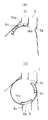
特願平7−193385号では、空調装置に配するロータリドアとして図に示すようなロータリドア50を挙げている。ロータリドア50の回動面50aにはゴムからなるシール部材51が固着されている。シール部材51は、ロータリドア50の回動面50aに対してほぼ垂直方向(ロータリドア50がケース(図示しない)に配設された際にケースの壁面へと向かう方向)へと伸び、可撓性を有する可撓性部分52を有している。
【0004】
この可撓性部分52は略矩形に設けられており、回動軸50bの軸方向に設けられる部分(以下、ヨコシール部52aとする)と、ロータリドア50の回動方向に沿って設けられる部分(以下、タテシール部52bとする)とを有している。
ロータリドア50は、可撓性部分52の先端がケースの壁面に当接し、撓んだ状態となるようにケース内に配設されており、可撓性部分52を撓ませた状態でケースの壁面に当接させることによって、ロータリドア50とケースの壁面との間はシールされる。
【0005】
【発明が解決しようとする課題】
しかしながら、本発明者らが鋭意検討したところ、前記特願平7−193385号に示されているようなロータリドアであると、以下に述べるような問題点があることが明らかとなった。
可撓性部分52のうちヨコシール部52aはロータリドア50の回動軸50bとほぼ平行に設けられているので、ロータリドア50の回動時にヨコシール部52aの先端は一方向に撓む。したがって、ロータリドア50の回動時に必要な操作力は比較的小さい。これに対して、タテシール部52bはロータリドア50の回動方向に沿って設けられているので、ロータリドア50の回動時にタテシール部52bの先端が撓む方向はロータリドア50の回動方向に対して左右に不規則となってしまう。そのため、ロータリドア50の回動時に大きな操作力が必要となるとともに、シール性が低下してしまうという問題点がある。
【0006】
そこで、本発明は上記問題に鑑みてなされたものであり、可撓性部分の先端を撓ませながらケースの壁面に当接させることによりロータリドアとケースとの間をシールする空調装置において、シール性を確保しつつロータリドアの操作力の低減させることを目的とするものである。
【0007】
【課題を解決するための手段】
上記目的を達成するため、請求項1記載の発明によれば、端面(6a)に形成される突起部(6f)がケース(1)に形成される溝部(1c)に遊嵌する構造となっているので、閉塞されるべきケースの開口部(8,9,10)に回動軸(6e)の軸方向に沿って流入しようとする空気は突起部と溝部との間隙を通過しようとする。しかし、この空気は突起部および溝部に沿って屈曲しながら通過するので、突起部と溝部との間隙の通風抵抗が大きくなり、回動軸の軸方向に沿って閉塞されるべきケースの開口部に流入しようとする空気の流れを実質的に遮ることができる。したがって、従来、ロータリドア(6)の回動方向に沿って設けられていた可撓性部分(従来技術の項におけるタテシール部(52b))によって遮られていた、回動軸の軸方向に沿って閉塞されるべきケースの開口部に流入しようとする空気の流れを遮ることができる。そのため、ロータリドアの回動方向に沿って設けられていた可撓性部分のうち端面側に設けられていた部分をなくすことができ、ロータリドアの操作力増大の原因となっていた、回動方向に沿って設けられる可撓性部分(13b)の長さを短くすることができる。ロータリドアを回動させる際に必要となる操作力を低減させることができる。なお、突起部は溝部に遊嵌されているので、ロータリドアを回動させる際に必要となる操作力を増大させることはない。
【0008】
さらに、可撓性部分(13a)の端部は突起部に接合しており、可撓性部分(13)と突起部とによって閉塞されるべきケースの開口部の周囲は囲まれているので、ロータリドアとケースの壁面との間のシール性を十分に保つことができる。
また、請求項2の発明によれば、ロータリドア(15)の形状を、径の大きさが異なる複数の回動面を積み重ねた形状とすることによって、壁面に回動軸(15h)の軸方向に複数の開口部(8、9、10)が形成されるケース(1)の内部に配されるロータリドアの各回動面の両端面(15a、15c)に突起部(15f、15g)を形成し、ケースの溝部に遊嵌させることによって、各回動面の両端側において、閉塞されるべきケースの開口部に回動軸の軸方向に沿って流入しようとする空気の流れを遮ることができる。したがって、従来、ロータリドアの回動方向に設けられていたタテシール部(52b)をすべてなくすことができ、ロータリドアを回動させる際に必要となる操作力をさらに低減させることができる。
【0009】
また、請求項3の発明によれば、ロータリドア(6)の回動軸(6e)の軸方向に沿って端面(6a)側から閉塞されるべきケース(1)の開口部(8、9、10)に流入しようとする空気の流れを、端面に設けられた可撓性部分(21a)によって遮ることができる。この端面に設けられる可撓性部分はロータリドアの回動方向に略垂直となるように設けられているので、ロータリドアが回動する際に撓む方向は一方向のみとなる。したがって、ロータリドアを回動させる際に必要となる操作力を低減させることができ、請求項1と同様の効果を得ることができる。なお、ロータリドアの突起部とケースの溝部が遊嵌した構造を有していなくても請求項1と同様の効果を得ることができ、請求項1の発明に比べて、より簡潔な構造とすることができる。
【0010】
さらに、請求項4の発明によれば、可撓性部分(13)の、端面(6a)に設けられ、端部が突起部(6f)に接合される部分は、ロータリドア(6)の回動方向に略垂直となるように設けられているので、ロータリドアの回動時にこの部分が撓む方向は一方向のみとなる。したがって、ロータリドアの端面とケース(1)の壁面との間のシール性を十分に保つことができるとともに、ロータリドアの回動させる際に必要とされる操作力を低減することができる。
【0011】
【発明の実施の形態】
次に、本発明を車両用空調装置として適用した第1実施例について図1ないし図9を用いて説明する。
内部に空気通路を有するケース1の空気上流側部位には送風機2が配設されている。この送風機2は図示しない駆動手段によって駆動される。また、ケース1の送風機2よりも上流側(図1紙面手前側)部位には、空気を吸入するための吸入口3が形成されている。そしてこの吸入口3には、図示しない圧縮機、凝縮器、減圧手段とともに周知の冷凍サイクルを構成する蒸発器を収納したクーラーユニットが接続されている。
【0012】
ケース1内のうち送風機2よりも空気下流側部位には通過する空気を加熱するヒータコア4が設けられている。ヒータコア4の空気上流側部位には、シャフト5aを中心に回転し、ヒータコア4を通過させる空気の量を調節するエアミックスドア5が設けられている。
また、ケース1のヒータコア4の空気下流側部位には、断面略円形状の部分1a、1aが、図1紙面手前側と奥側とにそれぞれ突出して形成されており、この部分1aに形成された突出部1bに後述するロータリードア6の回動軸6eが遊嵌され、回動自在に支持されることによって、ロータリードア6は上記1aと1aとの間にケース1に対して回動自在に支持される。
【0013】
この部分1aには、この部分1aに配されるロータリドア6の軸方向に、以下述べる複数のダクト7〜10が接続されるとともに、これらのダクト7〜10の空気最下流側部位となる開口部7a〜10aが形成されている。
上記の部分1aには、運転席乗員および助手席乗員の上半身のサイドガラス側部位またはサイドガラスに空調空気を導くサイドフェイスダクト7、7と、運転席乗員足元および助手席乗員足元に空調空気を導くフットダクト8、8とが接続されている。
【0014】
またケース1の空気下流端には、運転席乗員および助手席乗員の上半身中央部に空調空気を導くセンターフェイスダクト9と、フロントガラス内面に空調空気を導くデフロスタダクト10とが形成されている(図3参照)。
そして上記エアミックスドア5によってエアミックスされた空気は、ロータリードア6内に導かれ、このロータリードア6が後述する各開口部7a〜10a(図6〜図8参照)に沿うようにして上記回動軸6eを中心に回動し、停止した位置によって、上記各ダクト7〜10からの空気吹出量が調節される。
【0015】
次に、上記ロータリードア6の形状について説明する。
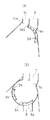
ロータリードア6は図1に示すように、外縁にリング状部分を有する2つの円板部6a(請求項における端面)と、リング状に形成された2つのリング部6bと、上記円板部6aとリング部6bとを連結する4枚(うち2枚は図4では隠れて図示されていない)の連結板6cと、上記リング部6bと6bとを連結する1枚の連結板6dと、ロータリドア6がケース1に配設された際にケース1の壁面に向けて伸びるよう円板部6aに立設される環状の突出部6fとがそれぞれ、図示しない所定の型によって樹脂で一体成形されており、全体として断面略円弧形状の略円筒形状を有している。また、円板部6a、6aの中心部には、円板部6aに対して突出した2つの円筒状の回動軸6e(うち1つは隠れて図示されていない)が形成されている。
【0016】
ロータリードア6が回動軸6eを中心に回動すると、円板部6aのリング状部分とリング部6bとの間の部位が上記ダクト7、8と対向し、リング部6bと6bとの間の部位が上記ダクト9、10と対向するように、ロータリドア6はケース1の内部に配置される。
なお、円板部6aのリング状部分とリング部6bとの間の部位のうち連結板6cが設けられていない部分、およびリング部6bと6bとの間の部位のうち連結板6dが設けられていない部分はロータリドアの内部と外部とが連通した状態となっており、請求項におけるロータリドアの開口部となっている。
【0017】
また、ロータリドア6の突出部6fと対向するケース1の壁面には溝部である溝1cが形成されており、ロータリドア6の突出部6fが遊嵌し、袋形状を成している。
ところで、円板部6a、および各連結板6c、6dのそれぞれの上面には、弾性体よりなるシール部材(具体的にはゴム)11、12が固着(具体的には接着剤によって接着)されている。このシール部材11、12には、自身を接着した連結板6c、6dに対して垂直となる方向(ロータリードア6をケース1内に配設した際に対向するケース1の壁面側に伸びる方向)に伸びる可撓性部分12、13がそれぞれ形成されている。この可撓性部分12、13は垂直方向における幅に対して、連結板6c、6dの面に水平な方向(ロータリードア6をケース1内に配設した後においてはロータリードア6が回動する方向)における幅が十分短く、ロータリードア6をケース1内に配設すると、ケース1の壁面に撓んだ状態(図4中実線で示す)で当接する。
【0018】
円板部6aおよび連結板6cに設けられる可撓性部分12は、ロータリドア6の回動方向に略垂直に設けられる部分(以下、ヨコシール部13aとする)と、ロータリドア6の回動方向に沿って設けられる部分(以下、タテシール部13bとする)とをそれぞれ有している。
ヨコシール部13aは略L字型形状を有しており、その一辺は連結板6cに接合されており、他辺は円板部6aに接合されている。なお、円板部6aに接合される部分の端部は突出部6fに接合されている。一方、タテシール部13bはヨコシール部13aのリング部6b側となる端部どうしを接続するように形成されており、ロータリドア6の回動方向に沿って設けられている。
【0019】
このように、ヨコシール部13aおよびタテシール部13bを設けることによって、ロータリドア6がケース1の内部に配設されると、開口部8aが閉塞される状態となると開口部8aの周囲は、突起部6f、ヨコシール部13aおよびタテシール部13bによって囲まれた状態となる。
続いて、本実施の形態の作動について述べる。
【0020】
吸入口3から吸入され、エバポレータ、ヒータコア4を通過した空気はロータリドア6の内部へと導かれる。ロータリドア6の内部に導かれた空気は、ロータリドア6の回動位置に応じてケース1の各開口部7a、8a、9a、10aへと流入し、各ダクト7、8、9、10へと送られる。
以下、ロータリードア6の回動位置と吹出モードとの関係を図6〜図8を用いて説明する。ここで図6〜図8はフェイスモード、フットモード、およびデフロスタモード時における図を示し、各図の(a)は図2のC−C矢視断面図、各図の(b)は図2のD−D矢視断面図である。
【0021】
先ず、図6に、センターフェイスダクト9およびサイドフェイスダクト7から空調風を吹き出すフェイスモードを示す。フェイスモード時には、図6(a)に示すように、ロータリードア6の連結板6dはデフロスタ開口部10aと対向する位置にあり、連結板6dによって開口部10aは閉塞された状態となっている。一方、図6(b)に示すように、ロータリードア6の連結板6cはフット開口部8aと対向する位置にあり、連結板6cによって開口部8aは閉塞された状態となっているとともに、センターフェイス開口部7aがほぼ全開に近い状態で開口される。
【0022】
次に、図7に、サイドフェイスダクト7およびフットダクト8から空調風を吹き出すとともに、デフロスタダクト10からも若干量の風を吹き出すフットモードを示す。フットモード時には、図7(a)に示すように、連結板6dはセンターフェイス開口部9aおよびデフロスタ開口部10aのほぼ全部と対向する位置にあり、連結板6dによって開口部9aおよびデフロスタ開口部10aは閉塞された状態となっている。一方、図7(b)に示すように、サイドフェイス開口部7aとフット開口部8aがともに全開状態となる。
【0023】
次に、図8に、デフロスタダクト10およびサイドフェイスダクト7から空調風を吹き出すデフロスタモードを示す。デフロスタモード時には、図8(a)に示すように、連結板6dはセンターフェイス開口部9aと対向する位置にあり、連結板6dによって開口部9aは閉塞され、デフロスタ開口部10aが全開される。一方、図8(b)に示すように、連結板6cはフット開口部8aと対向する位置にあり、連結板6cによってフット開口部8aは閉塞された状態となる。
【0024】
なお、図示はしなかったが、上記各連結板6c、6dが図6と図7の中間位置になるときに、サイドフェイスダクト7、フットダクト8、およびセンターフェイスダクト9から空調風を吹き出すバイレベルモードとなり、各連結板6c、6dが図7と図8の中間位置なるときに、フットダクト8およびデフロスタダクト10から空調風を吹き出すフットデフモードとなる。
【0025】
このように、ロータリドア6を回動させることによって、各吹出モードは切り替えられる。吹出しモードに応じて、開口部8aは連結板6cによって閉塞され、開口部9a、10aは連結板6dによって閉塞される。
ところで、ロータリドアの円板部6aには突起部6fが立設されており、この突起部6fは溝部1cに遊嵌されているため、開口部8aが閉塞される際に、ロータリドア6の内部から回動軸6eの軸方向に沿って開口部8aに流入しようとする空気は突起部6fと溝1cとの間隙を通過しようとする。
【0026】
しかし、この空気は突起部6fおよび溝1cに沿って屈曲しながら通過するので、突起部6fと溝1cとの間隙の通風抵抗が大きくなり、回動軸6eの軸方向に沿って閉塞されるべきケース1の開口部8aに円板部6a側から流入しようとする空気の流れを実質的に遮ることができる。したがって、従来、ロータリドア6の回動方向に沿って設けられていたタテシール部のうち円板部6a側に設けられていた部分をなくすことができ、ロータリドア6を回動させる際に必要とされる操作力を減少させることができる。
【0027】
一方、開口部8aが閉塞される際に、ロータリドア6の内部から、ロータリドア6の回動方向に沿って開口部8aに流入しようとする空気の流れのうち連結板6d側から流入しようとする空気の流れは、タテシール部13bが撓みながらケース1の壁面に当接することにより遮られる。また、ロータリドア6の回動方向に沿って開口部に8a流入しようとする空気の流れはヨコシール部13aが撓みながらケース1の壁面に当接することにより遮られる。
【0028】
また、開口部8aが閉塞される場合、開口部8aの周囲は突起部6f、ヨコシール部13aおよびタテシール部13bによって囲まれた状態となるように、突起部6f、ヨコシール部13aおよびタテシール部13bは設けられており、ロータリドア6とケース1の壁面との間のシール性を十分に保つことができる。
〔第2の実施の形態〕
また、ロータリドアの形状を、径の大きさが異なる略円弧形状の断面を有する複数の回動面が積み重ねられた形状とし、各回動面の両側の端面にケースに形成された溝に遊嵌する突起部を形成した構造としてもよい。以下、第1の実施の形態と同様の構造を有する部分については同じ符号を用いるとともに、その説明は省略する。
【0029】
図9および図10に示すように、ロータリドア15は、外縁にリング状部分を有する2つの円板部15aと、外縁に半円形の板状部分(以下、半円板部15cとする)を有し、径が円板部15aよりも大きい2つのリング部15bと、上記円板部15aとリング部15bとを連結する4枚(うち2枚は図4では隠れて図示されていない)の連結板15dと、上記リング部15bと15bとを連結する1枚の連結板15eと、円板部15aに立設される環状の突出部15fと、半円板部15cに立設される環状の突出部15gとがそれぞれ、図示しない所定の型によって樹脂で一体成形されている。また、円板部15a、15aの中心部には、円板部15aに対して突出した2つの円筒状の回動軸15h(うち1つは隠れて図示されていない)が形成されている。
【0030】
このロータリドア15は、円板部15aのリング状部分とリング部15bとの間の部位が上記ダクト7、8と対向し、リング部15bと15bとの間の部位が上記ダクト9、10と対向するように、ロータリドア15はケース1の内部に配置される。
円板部15aのリング状部分とリング部15bとの間の部位、およびリング部15bと15bとの間の部位はロータリドア15の回動面となっており、両部位ともその断面は略円弧形状となっている。ただし、15aのリング状部分とリング部15bとの間の部位によって構成される回動面の断面の径の大きさよりも、リング部15bと15bとの間の部位によって構成される回動面の断面の径の大きさのほうが大きい。
【0031】
なお、円板部15aおよび半円板部15cは、円板部15aのリング状部分とリング部15bとの間の部位によって構成される回動面の両端面となっており、半円板部15cおよび半円板部15cはリング部15bと15bとの間の部位によって構成される回動面の両端面となっている。
また、円板部15aのリング状部分とリング部15bとの間の部位のうち連結板15dが設けられていない部分、およびリング部15bと15bとの間の部位のうち連結板15eが設けられていない部分はロータリドア15の内部と外部とが連通した状態となっており、請求項におけるロータリドアの開口部となっている。
【0032】
なお、ロータリドア15の突出部15fと対向するケース1の壁面には溝部である溝1cが形成され、突出部15fが遊嵌しており、袋形状を成している。一方、突出部15gと対向するケース1の壁面には溝部である溝1dが形成され、突出部15gが遊嵌しており、袋形状を成している。
このように、円板部15a、半円板部15cにそれぞれ突出部15f、15gを形成し、ケース1に形成された溝部1c、1dに遊嵌させることによって、第1の実施の形態において述べたように、ロータリドア15の回動方向に沿ってロータリドア15の内部から開口部8aへと流入しようとする空気の流れを遮ることができる。
【0033】
円板部15aと連結板15dとにわたって設けられるシール部材16、および連結板15eに設けられるシール部材17は、第1の実施の形態におけるシール部材11、12と同様に弾性体(具体的にはゴム)よりなり、第1の実施の形態における可撓性部分13、14と同様に、自身を接着した連結板15d、15eに対して垂直な方向(ロータリードア15をケース1内に配設した際に、対向するケース1の壁面側に伸びる方向)に伸びる可撓性部分18、19がそれぞれ形成されている。
【0034】
連結板15dに設けられるシール部材16の可撓性部分18は、クランク形状を有しており、各辺は円板部15a、連結板15d、半円板部15cに、ロータリドア15の回動方向に略垂直となるようにそれぞれ接合されている。なお、円板部15aに設けられる可撓性部分18の部分の端部は突起部15fに、円板部15aに設けられる可撓性部分18の部分の端部は突起部15gにそれぞれ接合されている。
【0035】
一方、連結板15eに設けられるシール部材17の可撓性部分19は略コの字型形状を有しており、各辺は半円板部15c、連結板15e、半円板部15cにロータリドア15の回動方向に略垂直となるようにそれぞれ接合されている。なお、半円板部15cに設けられる可撓性部分19の部分の端部は突起部15gにそれぞれ接合されている。
【0036】
吹出モードを切り替えるためにロータリドア15が回動すると、開口部8aは連結板15dによって、開口部9a、10aは連結板15eによってそれぞれ開閉される。開口部8aが閉塞されると、開口部8aの周囲に可撓性部分18がケース1の壁面に撓みながら当接することによって、ロータリドア15の回動方向に沿って開口部8aへと流入しようとする空気の流れは遮られる。
【0037】
以上に述べたように、開口部9a、10aが閉塞されると、開口部9a、10aの周囲となるケース1の壁面とロータリドア15との間は袋形状およびシール部材16によってシールされた状態となる。
なお、本実施の形態では、特に、ロータリドア15を、径の大きさの異なる円板部15aとリング部15bとを連結板15d、15eによって連結した形状とすることによって、回動軸15hの軸方向に複数の開口部7a、8a、9a、10aがケース1に形成される空調装置において、各回動面の両端に袋形状を設けることができる。したがって、ロータリドア15の回動方向に沿ってロータリドア15の内部から開口部8aへと流入しようとする空気の流れのうち、円板部15a側から開口部8aに流入しようとする空気の流れだけでなく、半円板部15a側から開口部8aに流入しようとする空気の流れも遮ることができる。したがって、従来、設けられていたヨコシール部をすべてなくすことができ、ロータリドア15を回動させる際に必要となる操作力をさらに低減することができる。
〔第3の実施の形態〕
また、ロータリドアを、円板部に立設される突起部をなくし、ヨコシール部の円板部に接合される部分の端部をロータリドアの回動軸に接合させた構造としても、第1の実施の形態とほぼ同様の効果を得ることができる。なお、第1の実施の形態と同様の構造を有する部分については同じ符号を用いるとともに、その説明は省略する。
【0038】
図11または12に示すように、ロータリドア6の円板部6aおよび連結板6cには、第1の実施の形態におけるシール部材11と同様の材質からなるシール部材20が接合されている。シール部材20は、連結板6cに対して垂直方向(ロータリードア6をケース1内に配設した際に対向するケース1の壁面側に伸びる方向)に伸びる可撓性部分21が形成されている。可撓性部分21は、ロータリドア6の回動軸6eの軸方向に設けられるタテシール部21bと、ロータリドア6の回動方向に沿って設けられるヨコシール部21aとを有している。
【0039】
ヨコシール部21aは略L字型形状を有しており、一辺は円板部6aに、他辺は連結板6cにそれぞれ接合されている。ヨコシール部21aのうち、円板部6aに設けられる部分の端部はロータリドア6の回動軸6eに接合されている。
一方、タテシール部21bは、ヨコシール部21aの、連結板6cに設けられる部分の端部どうしを接続するように形成される。
【0040】
ロータリドア6がケース1の内部に配設されると、開口部8が閉塞される際には開口部8の周囲は、撓みながらケースの壁面に当接するヨコシール部21aおよび、タテシール部21bによって囲まれた状態となる。そのため、ロータリドア6の内部を通過し、開口部8へと流入しようとする空気をヨコシール部21a、タテシール部21bによって遮ることができ、ロータリドアとケースの壁面との間をシールすることができる。
【0041】
なお、ヨコシール部21aの円板部6aに設けられている部分はロータリドアの回動方向に略垂直に設けられているので、ロータリドア6が回動する際に撓む方向は一方向のみである。したがって、ロータリドア6を回動させる際に必要とされる操作力を低減させることができる。
また、第1の実施の形態のように、突出部を円板部に、溝をケースにそれぞれ形成しなくても、第1の実施の形態と同様の効果を得ることができるので、ロータリドアおよびケースをより簡潔な構造とすることができる。
【図面の簡単な説明】
【図1】本発明の第1の実施の形態におけるロータリドアの全体構成を示す斜視図である。
【図2】空調装置の全体構成を示す正面図である。
【図3】図2のB矢視図である。
【図4】シール部材の状態を示す拡大図である。
【図5】円板面に垂直な面におけるロータリドアの断面図の一部拡大図である。
【図6】フェイスモード時における各吹出口の最下流側となる開口部を示す図であり、そのうち(a)はセンターフェイス吹出口およびデフロスタ吹出口の最下流側となる開口部の状態を、(b)はフット吹出口の最下流側となる開口部の状態をそれぞれ示す。
【図7】フットモード時における各吹出口の最下流側となる開口部を示す図であり、そのうち(a)はセンターフェイス吹出口およびデフロスタ吹出口の最下流側となる開口部の状態を、(b)はフット吹出口の最下流側となる開口部の状態をそれぞれ示す。
【図8】デフロスタモード時における各吹出口の最下流側となる開口部を示す図であり、そのうち(a)はセンターフェイス吹出口およびデフロスタ吹出口の最下流側となる開口部の状態を、(b)はフット吹出口の最下流側となる開口部の状態をそれぞれ示す。
【図9】第2の実施の形態におけるロータリドアの全体構成を示す斜視図である。
【図10】第2の実施の形態におけるロータリドアの、円板面に垂直な面での断面図の一部拡大図である。
【図11】第3の実施の形態におけるロータリドアの全体構成を示す斜視図である。
【図12】第3の実施の形態におけるロータリドアの、円板面に垂直な面での断面図の一部拡大図である。
【図13】従来におけるロータリドアの全体構成を示す斜視図である。
【符号の説明】
1 ケース
1c 溝部である溝
6 ロータリドア
6a ロータリドア6の端面である円板部
6e 回動軸
6f 突起部
7a 開口部
8a 開口部
9a 開口部
10a 開口部
11 シール部
13 可撓性部分
13a 可撓性部分13の回動軸6eの軸方向に沿って設けられる部分であるヨコシール部[0001]
BACKGROUND OF THE INVENTION
The present invention adjusts the amount of air blown from the opening of the case by rotating the substantially cylindrical rotary door about the rotation axis so that the rotation surface is along the opening formed in the case. The present invention relates to a vehicle air conditioner.
[0002]
[Prior art]
In an air conditioner that adjusts the amount of air blown from the opening of the case by rotating the rotary door as described above, a sealing member made of an elastic member is usually fixed to the rotating surface of the rotary door. Is brought into contact with the edge of the opening of the case to prevent wind leakage from between the rotary door and the case.
[0003]
The present inventors previously filed an application as Japanese Patent Application No. 7-193385 for an air conditioner having a sealing member on a rotary door.
Japanese Patent Application No. 7-193385 discloses a rotary door 50 as shown in the figure as a rotary door disposed in an air conditioner. A
[0004]
The
The rotary door 50 is disposed in the case so that the distal end of the
[0005]
[Problems to be solved by the invention]
However, as a result of intensive studies by the present inventors, it has become apparent that the rotary door as shown in the aforementioned Japanese Patent Application No. 7-193385 has the following problems.
Since the
[0006]
Accordingly, the present invention has been made in view of the above problems, and in an air conditioner that seals between the rotary door and the case by bringing the tip of the flexible portion into contact with the wall surface of the case, the seal The purpose is to reduce the operating force of the rotary door while ensuring the performance.
[0007]
[Means for Solving the Problems]
To achieve the above object, according to the first aspect of the present invention, the protrusion (6f) formed on the end face (6a) is loosely fitted in the groove (1c) formed on the case (1). Therefore, the air that is about to flow into the opening (8, 9, 10) of the case to be closed along the axial direction of the rotation shaft (6e) tends to pass through the gap between the protrusion and the groove. . However, since this air passes while bending along the protrusion and the groove, the ventilation resistance of the gap between the protrusion and the groove increases, and the opening of the case that should be blocked along the axial direction of the rotating shaft It is possible to substantially block the flow of air that is going to flow into the air. Therefore, conventionally, along the axial direction of the rotating shaft, which is blocked by the flexible portion (vertical seal portion (52b) in the section of the prior art) provided along the rotating direction of the rotary door (6). Thus, it is possible to block the flow of air that tends to flow into the opening of the case to be blocked. Therefore, the portion provided on the end face side of the flexible portion provided along the rotation direction of the rotary door can be eliminated, and the rotation that has caused an increase in the operating force of the rotary door. The length of the flexible portion (13b) provided along the direction can be shortened. The operating force required when rotating the rotary door can be reduced. In addition, since the projection part is loosely fitted in the groove part, the operation force required when rotating the rotary door is not increased.
[0008]
Furthermore, since the end of the flexible portion (13a) is joined to the protrusion, and the periphery of the opening of the case to be closed by the flexible portion (13) and the protrusion is surrounded, The sealing property between the rotary door and the wall surface of the case can be sufficiently maintained.
According to the invention of claim 2, the rotary door (15) has a shape in which a plurality of rotating surfaces having different diameters are stacked, so that the shaft of the rotating shaft (15h) is formed on the wall surface. Protrusions (15f, 15g) on both end faces (15a, 15c) of each rotary surface of the rotary door disposed inside the case (1) in which a plurality of openings (8, 9, 10) are formed in the direction. By forming and loosely fitting into the groove portion of the case, it is possible to block the flow of air that is about to flow along the axial direction of the rotating shaft into the opening portion of the case to be closed on both ends of each rotating surface. it can. Therefore, it is possible to eliminate all the vertical seal portions (52b) conventionally provided in the rotating direction of the rotary door, and it is possible to further reduce the operating force required when rotating the rotary door.
[0009]
According to the invention of claim 3, the openings (8, 9) of the case (1) to be closed from the end face (6a) side along the axial direction of the rotating shaft (6e) of the rotary door (6). 10) can be blocked by the flexible portion (21a) provided on the end face. Since the flexible portion provided on the end face is provided so as to be substantially perpendicular to the rotational direction of the rotary door, the direction of bending when the rotary door rotates is only one direction. Therefore, the operation force required when rotating the rotary door can be reduced, and the same effect as in the first aspect can be obtained. In addition, even if it does not have the structure which the protrusion part of the rotary door and the groove part of the case loosely fitted, the effect similar to
[0010]
Furthermore, according to the invention of
[0011]
DETAILED DESCRIPTION OF THE INVENTION
Next, a first embodiment in which the present invention is applied as a vehicle air conditioner will be described with reference to FIGS.
A blower 2 is disposed at an upstream side portion of the
[0012]
In the
Further, in the air downstream side portion of the
[0013]
A plurality of
The
[0014]
In addition, a center face duct 9 that guides conditioned air to the center of the upper half of the driver and passenger occupants and a
The air mixed by the
[0015]
Next, the shape of the
As shown in FIG. 1, the
[0016]
When the
In addition, the
[0017]
A
By the way, sealing members (specifically, rubber) 11 and 12 made of an elastic body are fixed (specifically, bonded by an adhesive) to the upper surfaces of the
[0018]
The
The
[0019]
Thus, when the
Next, the operation of this embodiment will be described.
[0020]
Air sucked from the suction port 3 and passed through the evaporator and the
Hereinafter, the relationship between the rotational position of the
[0021]
First, FIG. 6 shows a face mode in which conditioned air is blown from the center face duct 9 and the
[0022]
Next, FIG. 7 shows a foot mode in which conditioned air is blown out from the
[0023]
Next, FIG. 8 shows a defroster mode in which conditioned air is blown out from the
[0024]
Although not shown, when each of the connecting
[0025]
Thus, each blowing mode is switched by rotating the
By the way, since the
[0026]
However, since this air passes while being bent along the
[0027]
On the other hand, when the
[0028]
Further, when the
[Second Embodiment]
In addition, the rotary door has a shape in which a plurality of rotating surfaces having substantially arc-shaped cross sections with different diameters are stacked, and is loosely fitted in grooves formed in the case on both end surfaces of each rotating surface. It is good also as a structure which formed the projection part to perform. Hereinafter, the same reference numerals are used for portions having the same structure as in the first embodiment, and description thereof is omitted.
[0029]
As shown in FIGS. 9 and 10, the
[0030]
In the
A portion between the ring-shaped portion of the
[0031]
In addition, the
Further, a portion between the ring-shaped portion of the
[0032]
In addition, the
As described in the first embodiment, the projecting portions 15f and 15g are formed in the
[0033]
The
[0034]
The
[0035]
On the other hand, the
[0036]
When the
[0037]
As described above, when the
In the present embodiment, in particular, the
[Third Embodiment]
In addition, the rotary door may have a structure in which the protruding portion erected on the disc portion is eliminated and the end portion of the horizontal seal portion joined to the disc portion is joined to the rotary shaft of the rotary door. The substantially same effect as that of the embodiment can be obtained. In addition, while using the same code | symbol about the part which has the structure similar to 1st Embodiment, the description is abbreviate | omitted.
[0038]
As shown in FIG. 11 or 12, a
[0039]
The
On the other hand, the
[0040]
When the
[0041]
In addition, since the part provided in the
Further, as in the first embodiment, the same effect as in the first embodiment can be obtained without forming the projecting portion in the disk portion and the groove in the case. And the case can have a simpler structure.
[Brief description of the drawings]
FIG. 1 is a perspective view showing an overall configuration of a rotary door according to a first embodiment of the present invention.
FIG. 2 is a front view showing the overall configuration of the air conditioner.
FIG. 3 is a view taken in the direction of arrow B in FIG. 2;
FIG. 4 is an enlarged view showing a state of a seal member.
FIG. 5 is a partially enlarged view of a sectional view of the rotary door in a plane perpendicular to the disk surface.
FIG. 6 is a view showing an opening on the most downstream side of each outlet in the face mode, in which (a) shows the state of the opening on the most downstream side of the center face outlet and the defroster outlet; (B) shows the state of the opening part which becomes the most downstream side of a foot blower outlet, respectively.
FIG. 7 is a diagram showing an opening on the most downstream side of each outlet in the foot mode, in which (a) shows the state of the opening on the most downstream side of the center face outlet and the defroster outlet; (B) shows the state of the opening part which becomes the most downstream side of a foot blower outlet, respectively.
FIG. 8 is a diagram showing an opening on the most downstream side of each outlet in the defroster mode, in which (a) shows the state of the opening on the most downstream side of the center face outlet and the defroster outlet; (B) shows the state of the opening part which becomes the most downstream side of a foot blower outlet, respectively.
FIG. 9 is a perspective view showing an overall configuration of a rotary door according to a second embodiment.
FIG. 10 is a partially enlarged view of a sectional view of a rotary door according to a second embodiment, taken along a plane perpendicular to the disc surface.
FIG. 11 is a perspective view showing an overall configuration of a rotary door according to a third embodiment.
FIG. 12 is a partially enlarged view of a sectional view of a rotary door according to a third embodiment, taken along a plane perpendicular to the disk surface.
FIG. 13 is a perspective view showing an overall configuration of a conventional rotary door.
[Explanation of symbols]
1 case
1c Groove that is a groove
6 Rotary door
6a Disk part which is the end surface of the
6e Rotating shaft
6f Protrusion
7a opening
8a opening
9a opening
10a opening
11 Sealing part
13 Flexible part
13a Horizontal seal part which is a part provided along the axial direction of the
Claims (4)
このケースに回動自在に支持される回動軸と、
開口部が形成される断面略円弧形状の回動面を有し、前記ケースの内部に前記回動軸に連結されて配置されるロータリドアと、
このロータリドアに設けられ、先端が対向するケースの壁面に向けて伸びる可撓性部分を有し、この可撓性部分を撓ませながら前記ケースの壁面に当接させることにより前記ロータリドアと前記ケースの壁面との間をシールするシール部材と
を有し、
前記ケースの前記ロータリドアの開口部と対向する位置に開口部が形成され、前記ロータリードアを前記回動軸を中心に回動させることによって前記ケースの開口部からの空気吹出量を調節する空調装置において、
前記ロータリドアの前記回動面の端面に、前記ロータリドアの回動方向に沿って突起部が立設され、
この突起部が立設される前記端面と対向するケースの壁面に前記突起部が遊嵌する溝部が形成され、
前記可撓性部分の端部が前記突起部に接合し、閉塞されるべき前記ケースの開口部の周囲を前記突起部と前記可撓性部分とによって囲むように前記シール部材が前記ロータリドアに設けられることを特徴とする空調装置。A case having an air passage inside,
A pivot shaft rotatably supported by the case;
A rotary door having a rotation surface having a substantially arc-shaped cross section in which an opening is formed, and being connected to the rotation shaft inside the case;
The rotary door is provided with a flexible portion that extends toward the wall surface of the case facing the tip, and the flexible door is brought into contact with the wall surface of the case while bending the flexible portion. A seal member for sealing between the wall surface of the case,
An air conditioner in which an opening is formed at a position opposite to the opening of the rotary door of the case, and the amount of air blown from the opening of the case is adjusted by rotating the rotary door about the rotating shaft. In the device
On the end surface of the rotary surface of the rotary door, a protrusion is erected along the rotational direction of the rotary door,
A groove portion in which the protrusion portion is loosely fitted is formed on the wall surface of the case facing the end surface where the protrusion portion is erected,
The seal member is attached to the rotary door so that the end of the flexible portion is joined to the protrusion and the periphery of the opening of the case to be closed is surrounded by the protrusion and the flexible portion. An air conditioner provided.
開口部が形成される断面略円弧形状の回動面を有し、前記ケースの内部に前記回動軸に連結されて配置されるロータリドアと、
このロータリドアに設けられ、先端が対向するケースの壁面に向けて伸びる可撓性部分を有し、この可撓性部分を撓ませながら前記ケースの開口部の周囲に当接させることにより前記ロータリドアと前記ケースの開口部の周囲との間をシールするシール部材と
を有し、
前記ロータリードアを前記回動軸を中心に回動させることによって前記ケースの開口部からの空気吹出量を調節する空調装置において、
前記可撓性部分が、前記ロータリドアの回動方向に略垂直となるように、前記ロータリドアの前記回動面の端面の少なくとも一方の端面に設けられ、前記回動軸に接合されることを特徴とする空調装置。A case having an air passage therein and having an opening, a pivot shaft rotatably supported by the case,
A rotary door having a rotation surface having a substantially arc-shaped cross section in which an opening is formed, and being connected to the rotation shaft inside the case;
The rotary door has a flexible portion that extends toward the wall surface of the case facing the front end, and the rotary portion is brought into contact with the periphery of the opening of the case while bending the flexible portion. A seal member that seals between the door and the periphery of the opening of the case;
In the air conditioner that adjusts the amount of air blown from the opening of the case by rotating the rotary door around the rotation shaft,
The flexible portion is provided on at least one end surface of the rotating surface of the rotary door so as to be substantially perpendicular to the rotating direction of the rotary door, and is joined to the rotating shaft. An air conditioner characterized by.
Priority Applications (1)
| Application Number | Priority Date | Filing Date | Title |
|---|---|---|---|
| JP20963996A JP3671533B2 (en) | 1996-08-08 | 1996-08-08 | Air conditioner |
Applications Claiming Priority (1)
| Application Number | Priority Date | Filing Date | Title |
|---|---|---|---|
| JP20963996A JP3671533B2 (en) | 1996-08-08 | 1996-08-08 | Air conditioner |
Publications (2)
| Publication Number | Publication Date |
|---|---|
| JPH1053017A JPH1053017A (en) | 1998-02-24 |
| JP3671533B2 true JP3671533B2 (en) | 2005-07-13 |
Family
ID=16576127
Family Applications (1)
| Application Number | Title | Priority Date | Filing Date |
|---|---|---|---|
| JP20963996A Expired - Fee Related JP3671533B2 (en) | 1996-08-08 | 1996-08-08 | Air conditioner |
Country Status (1)
| Country | Link |
|---|---|
| JP (1) | JP3671533B2 (en) |
Families Citing this family (6)
| Publication number | Priority date | Publication date | Assignee | Title |
|---|---|---|---|---|
| US5269144A (en) * | 1991-09-10 | 1993-12-14 | Detroit Diesel Corporation | Methanol fueled turbocharged diesel cycle internal combustion engine |
| KR20000032411A (en) * | 1998-11-14 | 2000-06-15 | 신영주 | Temp door of vehicle air conditioner |
| WO2004078497A1 (en) | 2003-01-11 | 2004-09-16 | Halla Climate Control Corp. | Air conditioning system for automobiles |
| JP3841063B2 (en) * | 2003-04-25 | 2006-11-01 | 株式会社デンソー | Air passage opening and closing device and vehicle air conditioner |
| EP1641642B1 (en) * | 2003-06-30 | 2009-11-25 | Behr GmbH & Co. KG | Air-conditioning system |
| BRPI0800275B1 (en) * | 2008-01-18 | 2019-09-24 | Valeo Sistemas Automotivos Ltda | SINGLE GATE FOR CLOSING CENTRAL AND SIDE AIR OUTLETS IN AN AUTOMOTIVE VEHICLE CLIMATE HABIT |
-
1996
- 1996-08-08 JP JP20963996A patent/JP3671533B2/en not_active Expired - Fee Related
Also Published As
| Publication number | Publication date |
|---|---|
| JPH1053017A (en) | 1998-02-24 |
Similar Documents
| Publication | Publication Date | Title |
|---|---|---|
| JP4300340B2 (en) | Airway switching door | |
| JP3575495B2 (en) | Vehicle air conditioner | |
| JP3858712B2 (en) | Air conditioner for vehicles | |
| US6786816B2 (en) | Inside/outside air switching device for vehicular air conditioning unit | |
| US6435960B2 (en) | Inside/outside air switching device with rotary door | |
| JP3671533B2 (en) | Air conditioner | |
| JPH09188124A (en) | Air-opening opening and closing device | |
| JP3505911B2 (en) | Vehicle air conditioner | |
| JP2013133069A (en) | Air conditioner for vehicle | |
| JP3257547B2 (en) | Vehicle air conditioner | |
| JP3633044B2 (en) | Air conditioner | |
| JP4618193B2 (en) | Air passage opening and closing device | |
| JPH1081122A (en) | Intake door device of air conditioner for vehicle | |
| JP3671540B2 (en) | Air passage switching device and vehicle air conditioner | |
| JP4092632B2 (en) | Door mounting structure | |
| JP3584525B2 (en) | Air passage switching device | |
| JP3933026B2 (en) | Air passage opening and closing device and manufacturing method thereof | |
| JP3694952B2 (en) | Inside / outside air switching device for vehicle air conditioning | |
| JP3462676B2 (en) | Vehicle air conditioner | |
| JPH01186414A (en) | Outside/inside air intake device for car air-conditioner | |
| JP3951703B2 (en) | Air conditioner for vehicles | |
| JP4164956B2 (en) | Air conditioner for vehicles | |
| JPH11348539A (en) | Air passage opening/closing device and air conditioner for vehicle | |
| JPH11123922A (en) | Air conditioner for vehicle | |
| US11745560B2 (en) | Blower unit |
Legal Events
| Date | Code | Title | Description |
|---|---|---|---|
| A977 | Report on retrieval |
Free format text: JAPANESE INTERMEDIATE CODE: A971007 Effective date: 20050315 |
|
| TRDD | Decision of grant or rejection written | ||
| A01 | Written decision to grant a patent or to grant a registration (utility model) |
Free format text: JAPANESE INTERMEDIATE CODE: A01 Effective date: 20050329 |
|
| A61 | First payment of annual fees (during grant procedure) |
Free format text: JAPANESE INTERMEDIATE CODE: A61 Effective date: 20050411 |
|
| R150 | Certificate of patent or registration of utility model |
Free format text: JAPANESE INTERMEDIATE CODE: R150 |
|
| LAPS | Cancellation because of no payment of annual fees |