JP3671296B2 - Suspended planar shield device - Google Patents
Suspended planar shield device Download PDFInfo
- Publication number
- JP3671296B2 JP3671296B2 JP2002160784A JP2002160784A JP3671296B2 JP 3671296 B2 JP3671296 B2 JP 3671296B2 JP 2002160784 A JP2002160784 A JP 2002160784A JP 2002160784 A JP2002160784 A JP 2002160784A JP 3671296 B2 JP3671296 B2 JP 3671296B2
- Authority
- JP
- Japan
- Prior art keywords
- planar
- guide rails
- suspended
- shields
- planar shield
- Prior art date
- Legal status (The legal status is an assumption and is not a legal conclusion. Google has not performed a legal analysis and makes no representation as to the accuracy of the status listed.)
- Expired - Fee Related
Links
Images


Landscapes
- Support Devices For Sliding Doors (AREA)
- Curtains And Furnishings For Windows Or Doors (AREA)
Description
【0001】
【発明の属する技術分野】
本発明は、フロアーやホール等の建物の大広間を拡縮自在に間仕切るために、或いは、窓や出入口等の建物の開口部を開閉するために、移動可能に吊り下げて使用される吊下式面状遮蔽体に関するものである。
【0002】
【従来の技術】
この種の面状遮蔽体は、大広間の天井や開口部の上枠に取り付けたガイドレールを走行するランナーに上縁を連結し、開閉移動して使用される。大広間や広い開口部に複数枚の面状遮蔽体を並べて吊り下げる場合、大広間や開口部を広く開放することが出来るようにするため、その面状遮蔽体の枚数に応じた複数本のガイドレールを平行に並べて取り付け、その各ガイドレール毎に1枚の面状遮蔽体を吊るし、それらを移動して大広間や開口部を開放するときはガイドレールの片端に重ね合わせになって片付けられるようになっている。
【0003】
【発明が解決しようとする課題】
そのように複数枚の面状遮蔽体を並べて大広間や開口部に設置する場合、それらを移動して大広間を仕切り、或いは、開口部を閉じるとき、その閉じ合わされて重なり合う面状遮蔽体の側縁と側縁の間に隙間が出来ないようにするには、平行に並べるガイドレールとガイドレールの間隔が重なり合う面状遮蔽体の側縁と側縁の厚みの合計寸法の半分になるように、ガイドレールの位置合わせを正確に行わなければならない。しかし、面状遮蔽体には、カーテンのようにガイドレールの太さに比して著しく薄手のものもある。そのように薄手の面状遮蔽体を複数枚並べて吊るす場合には、ガイドレールの太さと面状遮蔽体の厚みとの差に応じた隙間が、閉じ合わされて重なり合う面状遮蔽体の側縁と側縁の間に必然的に生じ、その間に隙間なく大広間を間仕切り、或いは、開口部を閉じることは出来ず、又、複数枚の面状遮蔽体を面一に揃えることは出来ない。
【0004】
【発明の目的】
そこで本発明は、カーテンのようにガイドレールの太さに比して著しく薄手の面状遮蔽体を複数枚並べて吊るす場合でも、隣合う面状遮蔽体と面状遮蔽体の間に隙間が出来ないようにし、又、その複数枚の面状遮蔽体の間が同一面上(面一)に揃うようにすることを目的とする。
【0005】
【課題を解決するための手段】
本発明に係る吊下式面状遮蔽体装置は、2本のガイドレール51・52を、それらのランナー61・62が触れて走行するランナー走行面を外向きにし、平行に向かい合わせて接合し、複数枚の面状遮蔽体10・11・12・13のそれぞれを、各面状遮蔽体の上縁70の一端を前記2本の中の何れか1本のガイドレール51を走行するランナー61に連結し、その各面状遮蔽体の上縁70の他端を前記2本の中の他の1本のガイドレール52を走行するランナー62に連結して、それら2本のガイドレール51・52に、それらの複数枚の面状遮蔽体10・11・12・13を移動可能に、且つ、開いた際に隣合う面状遮蔽体10と11,11と12,12と13………がガイドレールの長さ方向に斜めになって重なり合うように吊り下げたことを第1の特徴とする。
【0006】
本発明に係る吊下式面状遮蔽体装置の第2の特徴は、上記第1の特徴に加えて、面状遮蔽体10が、可撓性面状体72の上縁70に支桿40を取り付けて構成され、その支桿40から可撓性面状体72が吊り降ろされている点にある。
【0007】
本発明に係る吊下式面状遮蔽体装置の第3の特徴は、上記第1および第2の何れかの特徴に加えて、2本のガイドレール51・52の間に平板体63が挟み込まれており、その平板体63を介してそれら2本のガイドレール51・52が接合されている点にある。
【0008】
【発明の実施の形態】
ガイドレール51・52には、背面23の両縁から側面24・24に続いていてC字形乃至コ字形断面を成し、両側面24・24の間がランナー走行溝25になっており、ランナー走行溝25を挟んで向き合う溝縁26・27にランナーが引っ掛かって走行するチャネル型レールが主として使用される。
【0009】
図1と図2は、2本のチャネル型レール51・52の背面同士(23・23)を向かい合わせにし、平板体63を介して接合されたガイドレールを示し、ランナー走行溝25を前後方向(面状遮蔽体の表裏方向)に向けて使用することも出来(図1)、又、ランナー走行溝25を上下方向(垂直方向)に向けて使用することも出来る(図2)。
【0010】
図3と図4と図5は、2本のチャネル型レール51・52の側面同士(24・24)を向かい合わせにし、平板体を介して接合されたガイドレールを示し、ランナー走行溝25を前後方向(面状遮蔽体の表裏方向)に向けて使用することも出来(図3)、又、ランナー走行溝25を上下方向(垂直方向)に向けて使用することも出来る(図4)。
【0011】
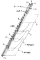
図3と図4に示す2本のチャネル型レール51・52は、ランナー走行溝25・25を同じ方向に向けられているが、それらのランナー走行溝25・25を、図1と図2に図示するガイドレールのように表裏逆向きにし、且つ、2本のチャネル型レール51・52を、図3に図示するガイドレールのように上下に重なる垂直方向に向けて使用すると、幅Wが狭くてガイドレールが嵩張らず、複数枚の面状遮蔽体10・11・12・13の上縁70が揃って水平に並んで均衡がとれるので好都合である(図5)。この場合、チャネル型レール51・52の間に挟み込んだ平板体63は、上下にL字状に折り曲げ、チャネル型レール51・52の背面23・23にビス止め固定する。
【0012】
図6は、2本のチャネル型レール51・52の背面23と側面24を向かい合わせにし、平板体(図示せず)を介して接合されたガイドレールを示す。図7は、ウエブ31の両縁でフランジ32が交るI形乃至H形断面、或いは、ウエブ31の片縁でフランジ32が交る逆T形断面を成し、フランジ32の両縁33・33にランナー61・62が引っ掛かって走行する2本のランナー露出型レール51・52のウエブ31とウエブ31の間に平板体(63)を挟み込んで接合したガイドレールを示す。
【0013】
面状遮蔽体10は、平板な硬板体の表裏を表装して扉や襖のように、又は、格子状に組み立てられた枠体の表裏を表装して障子のように、或いは、布帛やフイルム等の可撓性面状体72の上縁70を硬質支桿40に固定して垂れ幕やカーテンのように、或いは又、硬質支桿(72)から吊り降ろした連結紐に多数のスラット(羽根板)を取り付けてブラインドや簾のように構成することも出来る。垂れ幕、カーテン、ブラインド、簾のように可撓な面状遮蔽体(10)では、ローマンシエードカーテンやベネシァンブラインドのように昇降コードによってたくし上げて開閉し得るように構成することも出来る。
【0014】
面状遮蔽体10の上縁70の一端は2本のガイドレールの中の一方のガイドレール51を走行するランナー61に、その他端は他方のガイドレール52を走行するランナー62に連結する。尚、順次並べて吊り下げされた複数枚の面状遮蔽体10・11・12・13の中の端側の面状遮蔽体(10・13)は、2本の中の何れか一方のガイドレール51(52)を走行する2個のランナー(60・61)に連結してもよい(図3)。
【0015】
【発明の効果】
本発明によると、複数枚の面状遮蔽体10・11・12・13は、それらをガイドレールの長さ方向に順次並べ、その全ての上縁70の先端部を2本の中の1本のガイドレール(51)を走行するランナー(61)に連結し、その全ての上縁70の後端部を2本の中の他の1本のガイドレール(52)を走行するランナー(56)に連結して大広間の天井や開口部の上枠に吊るして開閉・移動して使用され、その大広間や開口部を開放するためにガイドレールの片側に引き寄せるときは、恰も1枚の面状遮蔽体が吊り下げられているかのように、複数枚の面状遮蔽体10・11・12・13が表裏方向に重なり合い、大広間や開口部を広く開放することが出来る。このため、3枚以上の面状遮蔽体を吊り下げるときでも、その枚数に応じた3本以上のガイドレールを必要とせず、面状遮蔽体の枚数に無関係にガイドレールの本数は2本で済み、その取付施工が楽になり、配列したガイドレールや重なり合う面状遮蔽体の数に比例して室内が狭められることもなくなる。そして、面状遮蔽体が、カーテンのようにガイドレールの太さに比して著しく薄手のものであっても、ガイドレールの長さ方向に斜めになって重なり合うので、隣合う面状遮蔽体と面状遮蔽体の間に隙間が出来難く、複数枚の面状遮蔽体の間が同一面上(面一)に揃い、整然とした外観を呈することになる。又、平板体63を介して2本のガイドレール51・52を接合するときは、恰も1本の桿状部材に2筋のランナー走行溝を付けたかのように、2本のガイドレールがコンパクトに一体化され、開口部の上枠や天井に取り付け易く、本発明の実施が簡便になる。
【図面の簡単な説明】
【図1】本発明に係る吊下式面状遮蔽体装置の要部斜視図である。
【図2】本発明に係る吊下式面状遮蔽体装置の要部斜視図である。
【図3】本発明に係る吊下式面状遮蔽体装置の要部斜視図である。
【図4】本発明に係る吊下式面状遮蔽体装置の要部斜視図である。
【図5】本発明に係る吊下式面状遮蔽体装置の要部斜視図である。
【図6】本発明に係る吊下式面状遮蔽体装置の要部斜視図である。
【図7】本発明に係る吊下式面状遮蔽体装置の要部斜視図である。
【符号の説明】
10・11・12・13 面状遮蔽体
23 背面
24 側面
25 ランナー走行溝
26・27 溝縁
31 ウエブ
32 フランジ
33 フランジの縁
40 支桿
51・52 ガイドレール
60・61・62 ランナー
63 平板体
70 上縁
72 可撓性面状体[0001]
BACKGROUND OF THE INVENTION
The present invention is a suspended type that is used to hang movably to partition a large hall of a building such as a floor or a hall, or to open and close an opening of a building such as a window or an entrance. The present invention relates to a planar shield.
[0002]
[Prior art]
This type of planar shield is used by connecting the upper edge to a runner running on a guide rail attached to the ceiling of the salon or the upper frame of the opening, and moving to open and close. When suspending a plurality of planar shields side by side in a saloon or wide opening, a plurality of guide rails corresponding to the number of planar shields can be used to widen the salon or opening. Are mounted side by side, and one planar shield is hung for each guide rail, and when they are moved to open the hall or opening, they are superposed on one end of the guide rail so that they can be cleaned up. It has become.
[0003]
[Problems to be solved by the invention]
When arranging a plurality of planar shields side by side in a salon or opening, they are moved to partition the salon, or when the opening is closed, the side edges of the planar shields that are closed and overlapped In order to prevent a gap between the side edge and the guide rails arranged in parallel, the distance between the guide rails and the guide rails arranged in parallel is half the total dimension of the thickness of the side edge and the side edge of the overlapping planar shield. The guide rail must be accurately aligned. However, some planar shields are extremely thin compared to the thickness of the guide rail, such as a curtain. When suspending a plurality of thin planar shields side by side, a gap corresponding to the difference between the thickness of the guide rail and the thickness of the planar shield is closed and overlapped with the side edges of the planar shields that overlap. It is inevitably generated between the side edges, and it is impossible to partition the hall without any gap between them or to close the opening, and it is not possible to align a plurality of planar shields.
[0004]
OBJECT OF THE INVENTION
Therefore, the present invention can create a gap between adjacent planar shields even when a plurality of planar shields that are extremely thin compared to the thickness of the guide rails are suspended. Another object of the present invention is to prevent the plurality of planar shields from being aligned on the same plane.
[0005]
[Means for Solving the Problems]
The suspended planar shield device according to the present invention joins two
[0006]
The second feature of the suspended planar shield device according to the present invention is that, in addition to the first feature, the
[0007]
A third feature of the suspended planar shield device according to the present invention is that the flat plate 63 is sandwiched between the two
[0008]
DETAILED DESCRIPTION OF THE INVENTION
The
[0009]
FIG. 1 and FIG. 2 show guide rails that are joined via a flat plate 63 with the back surfaces (23, 23) of the two channel-
[0010]
3, 4, and 5 show guide rails in which the side surfaces (24, 24) of the two
[0011]
The two channel-
[0012]
FIG. 6 shows a guide rail in which the
[0013]
The
[0014]
One end of the
[0015]
【The invention's effect】
According to the present invention, the plurality of
[Brief description of the drawings]
FIG. 1 is a perspective view of a main part of a suspended planar shield device according to the present invention.
FIG. 2 is a perspective view of a main part of a suspended planar shield device according to the present invention.
FIG. 3 is a perspective view of a main part of a suspended planar shield device according to the present invention.
FIG. 4 is a perspective view of an essential part of a suspended planar shield device according to the present invention.
FIG. 5 is a perspective view of an essential part of a suspended planar shield device according to the present invention.
FIG. 6 is a perspective view of a main part of a suspended planar shield device according to the present invention.
FIG. 7 is a perspective view of an essential part of a suspended planar shield device according to the present invention.
[Explanation of symbols]
10, 11, 12, 13
Claims (3)
Priority Applications (1)
| Application Number | Priority Date | Filing Date | Title |
|---|---|---|---|
| JP2002160784A JP3671296B2 (en) | 2002-05-31 | 2002-05-31 | Suspended planar shield device |
Applications Claiming Priority (1)
| Application Number | Priority Date | Filing Date | Title |
|---|---|---|---|
| JP2002160784A JP3671296B2 (en) | 2002-05-31 | 2002-05-31 | Suspended planar shield device |
Publications (2)
| Publication Number | Publication Date |
|---|---|
| JP2004003213A JP2004003213A (en) | 2004-01-08 |
| JP3671296B2 true JP3671296B2 (en) | 2005-07-13 |
Family
ID=30430036
Family Applications (1)
| Application Number | Title | Priority Date | Filing Date |
|---|---|---|---|
| JP2002160784A Expired - Fee Related JP3671296B2 (en) | 2002-05-31 | 2002-05-31 | Suspended planar shield device |
Country Status (1)
| Country | Link |
|---|---|
| JP (1) | JP3671296B2 (en) |
Families Citing this family (1)
| Publication number | Priority date | Publication date | Assignee | Title |
|---|---|---|---|---|
| EP1836369A4 (en) | 2004-11-04 | 2015-02-18 | Hunter Douglas | Single-track stacking panel covering for an architectural opening |
-
2002
- 2002-05-31 JP JP2002160784A patent/JP3671296B2/en not_active Expired - Fee Related
Also Published As
| Publication number | Publication date |
|---|---|
| JP2004003213A (en) | 2004-01-08 |
Similar Documents
| Publication | Publication Date | Title |
|---|---|---|
| US10544620B2 (en) | Single-Track stacking panel covering for an architectural opening | |
| ZA200503492B (en) | Curtain system comprising several flat panels | |
| JP3671296B2 (en) | Suspended planar shield device | |
| JP4257516B2 (en) | Shielding device | |
| AU2006227864B2 (en) | Single-track stacking panel covering for an architectural opening | |
| JP3682607B2 (en) | Surface shield suspended structure | |
| JP4263633B2 (en) | Shutter device | |
| TWI638088B (en) | Three-piece linkage | |
| USRE26269E (en) | Panel traversing and supporting means | |
| TWM613829U (en) | External mounted frame and external mounted curtain device | |
| JP2585114Y2 (en) | Fan curtain opening and closing device | |
| CA2559692A1 (en) | Panel track curtain system | |
| JP2004238819A (en) | Lower rail structure of plural door panels | |
| ES1059480U (en) | Separator of environments (Machine-translation by Google Translate, not legally binding) |
Legal Events
| Date | Code | Title | Description |
|---|---|---|---|
| A977 | Report on retrieval |
Free format text: JAPANESE INTERMEDIATE CODE: A971007 Effective date: 20040713 |
|
| A131 | Notification of reasons for refusal |
Free format text: JAPANESE INTERMEDIATE CODE: A131 Effective date: 20040817 |
|
| A521 | Written amendment |
Free format text: JAPANESE INTERMEDIATE CODE: A523 Effective date: 20040913 |
|
| A02 | Decision of refusal |
Free format text: JAPANESE INTERMEDIATE CODE: A02 Effective date: 20041214 |
|
| A521 | Written amendment |
Free format text: JAPANESE INTERMEDIATE CODE: A523 Effective date: 20041228 |
|
| A911 | Transfer of reconsideration by examiner before appeal (zenchi) |
Free format text: JAPANESE INTERMEDIATE CODE: A911 Effective date: 20050207 |
|
| TRDD | Decision of grant or rejection written | ||
| A01 | Written decision to grant a patent or to grant a registration (utility model) |
Free format text: JAPANESE INTERMEDIATE CODE: A01 Effective date: 20050322 |
|
| A61 | First payment of annual fees (during grant procedure) |
Free format text: JAPANESE INTERMEDIATE CODE: A61 Effective date: 20050405 |
|
| R150 | Certificate of patent or registration of utility model |
Free format text: JAPANESE INTERMEDIATE CODE: R150 |
|
| S533 | Written request for registration of change of name |
Free format text: JAPANESE INTERMEDIATE CODE: R313533 |
|
| R350 | Written notification of registration of transfer |
Free format text: JAPANESE INTERMEDIATE CODE: R350 |
|
| FPAY | Renewal fee payment (event date is renewal date of database) |
Free format text: PAYMENT UNTIL: 20080428 Year of fee payment: 3 |
|
| FPAY | Renewal fee payment (event date is renewal date of database) |
Free format text: PAYMENT UNTIL: 20090428 Year of fee payment: 4 |
|
| FPAY | Renewal fee payment (event date is renewal date of database) |
Free format text: PAYMENT UNTIL: 20090428 Year of fee payment: 4 |
|
| FPAY | Renewal fee payment (event date is renewal date of database) |
Free format text: PAYMENT UNTIL: 20100428 Year of fee payment: 5 |
|
| FPAY | Renewal fee payment (event date is renewal date of database) |
Free format text: PAYMENT UNTIL: 20100428 Year of fee payment: 5 |
|
| FPAY | Renewal fee payment (event date is renewal date of database) |
Free format text: PAYMENT UNTIL: 20110428 Year of fee payment: 6 |
|
| FPAY | Renewal fee payment (event date is renewal date of database) |
Free format text: PAYMENT UNTIL: 20120428 Year of fee payment: 7 |
|
| FPAY | Renewal fee payment (event date is renewal date of database) |
Free format text: PAYMENT UNTIL: 20120428 Year of fee payment: 7 |
|
| FPAY | Renewal fee payment (event date is renewal date of database) |
Free format text: PAYMENT UNTIL: 20130428 Year of fee payment: 8 |
|
| FPAY | Renewal fee payment (event date is renewal date of database) |
Free format text: PAYMENT UNTIL: 20140428 Year of fee payment: 9 |
|
| R250 | Receipt of annual fees |
Free format text: JAPANESE INTERMEDIATE CODE: R250 |
|
| R250 | Receipt of annual fees |
Free format text: JAPANESE INTERMEDIATE CODE: R250 |
|
| LAPS | Cancellation because of no payment of annual fees |