JP3671072B2 - Tension device for wire rope - Google Patents

Tension device for wire rope Download PDF

Info

Publication number
JP3671072B2
JP3671072B2 JP20524595A JP20524595A JP3671072B2 JP 3671072 B2 JP3671072 B2 JP 3671072B2 JP 20524595 A JP20524595 A JP 20524595A JP 20524595 A JP20524595 A JP 20524595A JP 3671072 B2 JP3671072 B2 JP 3671072B2
Authority
JP
Japan
Prior art keywords
wire rope
chuck
groove
fixed
frame
Prior art date
Legal status (The legal status is an assumption and is not a legal conclusion. Google has not performed a legal analysis and makes no representation as to the accuracy of the status listed.)
Expired - Fee Related
Application number
JP20524595A
Other languages
Japanese (ja)
Other versions
JPH0932888A (en
Inventor
進 菅
昭夫 櫛谷
Original Assignee
泉陽株式会社
Priority date (The priority date is an assumption and is not a legal conclusion. Google has not performed a legal analysis and makes no representation as to the accuracy of the date listed.)
Filing date
Publication date
Application filed by 泉陽株式会社 filed Critical 泉陽株式会社
Priority to JP20524595A priority Critical patent/JP3671072B2/en
Publication of JPH0932888A publication Critical patent/JPH0932888A/en
Application granted granted Critical
Publication of JP3671072B2 publication Critical patent/JP3671072B2/en
Anticipated expiration legal-status Critical
Expired - Fee Related legal-status Critical Current

Links

Images

Landscapes

  • Basic Packing Technique (AREA)

Description

【0001】
【産業上の利用分野】
この発明は、大形の荷物の梱包や、船舶等における荷崩れ防止のための荷物固縛(以下単にラッシングと言う)などを行う際に用いられる、ワイヤロープ用の緊張装置に関する。
【0002】
【従来の技術】
ワイヤロープを固縛材とする従来のラッシング作業においては、ターンバックル、シャックル、クリップ等の各種の固縛金具が不可欠であり、ロープの締め付けや固縛等の一連の作業を人手で行っている。そのため作業能率が低く、ラッシング作業に要する資材コストや人件費が高く付く。作業には熟練した専門作業者が不可欠であるため、例えば作業に急を要するような場合に、十分な人員を確保できないこともある。
【0003】
ラッシング作業を合理化するために、スチールベルトを固縛材とする作業方式が提唱され、ワイヤロープによる固縛作業方式を蚕食しつつある。そこでは、スチールベルトを緊張操作して固縛固定するための作業用機器が充実しているので、比較的容易にラッシング作業を行うことができるうえ、資材コストも少なくて済む。
この種の緊張装置は、例えば特公平1−32087号公報や、特開平5−229508号公報に公知である。
【0004】
【発明が解決しようとする課題】
スチールベルトを固縛材とする固縛作業においては、荷物に巻き掛けたベルトの中途部がねじれるのを避ける必要がある。そのため、ベルトの巻き掛けには細心の注意を払わねばならず、その分作業が面倒になる。例えば、段積みした鋼板コイルどうしを、ひと続きのスチールベルトで連結する場合に、ベルトがねじれない巻掛けパターンを選定しなければならない。
上記のように、スチールベルトで連結した一群の荷物を船体に固定する場合や、航海中の補強固縛用としては、依然としてワイヤロープが用いられており、二種類の固縛材を取り扱わねばならない点で、なお改善の余地がある。
【0005】
この発明の目的は、荷物等に巻き掛けたワイヤロープを自動的に緊張操作して、ロープエンドをクランプ筒で固定するのに好適なワイヤロープ用の緊張装置を提供することにある。
この発明の他の目的は、コンテナ内部や船倉内部等においてラッシング作業を行うのに好適な手持ち式のワイヤロープ用の緊張装置を提供することにある。
この発明の他の目的は、作業現場におけるラッシング作業や梱包作業を、少ない手間で能率良く行うことができ、作業に要する資材コストも少なく済むワイヤロープ用の緊張装置を提供することにある。
【0006】
【課題を解決するための手段】
この発明の緊張装置は、フレーム1と、フレーム1の両端に配置されて、ワイヤロープWの一端および他端側をそれぞれ挟持固定する一対の第1チャック2および第2チャック3を備えている。
フレーム1に前記両チャック2、3の少なくともいずれか一方を支持するスライダー4と、このスライダー4を往復動自在に案内支持するガイド5とを設ける。
フレーム1とスライダー4との間に、一方のチャック2を他方のチャック3から遠ざかる側へ移動操作する操作器6を設ける。
引き締め操作されるワイロープWの移動軌跡に臨んで、ワイヤロープWの緊張方向への移動は許すが、緩み方向への移動は阻止するストッパー7を設ける。
両チャック2、3の間に、クランプ筒42を装着するための装填部41を設ける。
【0007】
具体的には、操作器6を、スライダー4を兼ねるシリンダ−本体45と、ガイド5を兼ねて一端がフレ−ム1に固定してあるピストンロッド43とを有する操作シリンダ−で構成し、シリンダ−本体45に第1チャック2を固定し、フレ−ム1に第2チャック3を固定する。
両チャック2、3のそれぞれを、固定ブロック10、29と、固定ブロック10、29に対して接離自在に支持した可動ブロック11と、可動ブロック11、30を固定ブロック10、29に対して接離操作する挟持操作具12、12で構成する。固定ブロック10、29と可動ブロック11、30の対向面のそれぞれに、ワイヤロープWを挟持固定する挟持溝15、15と、ワイヤロープWの相対移動を許す通し溝16、16を設ける。
ストッパー7を、少なくとも一方のチャック3の通し溝16に臨んで配置したカム体33と、カム体33を通し溝16に対して出没旋回自在に支持する軸34と、カム体33を通し溝16へ向って進出付勢するばね37で構成する。
挟持溝15、15のそれぞれを部分円弧断面の溝で形成し、各溝の溝内面にワイヤロープWに対する摩擦抵抗を増加する突起17を形成する。
両チャック2、3のそれぞれを、固定ブロック10、29と、各固定ブロック10、29に対して一端が軸53、53で揺動自在に支持された可動ブロック11、30で構成する。両可動ブロック11、30の中途部に挟持溝15および通し溝16を形成し、両可動ブロック11、30の揺動先端寄りに挟持操作具12、12の操作端を連接する。
【0008】
【作用】
使用時には、第1チャック2と第2チャック3のうちの一方で、固縛対象に巻掛けたワイヤロープWの巻掛け始端を挟持し、他方でワイヤロープWの巻掛け終端を挟持固定する。両チャック2、3間の装填部41にはクランプ筒42を配置して、これに巻掛け始端と巻掛け終端のそれぞれを予め挿通しておく。この状態で操作器6を作動させて、例えば巻掛け終端側の第1チャック2をガイド5に沿って移動し、ワイヤロープWを引締め操作する。次に、第1チャック2の挟持力を解放して、引締め前の待機位置へ戻し、再びワイヤロープWを挟持固定した後、操作器6を作動させてワイヤロープWを引締め操作し、この動作を繰り返えし行ってワイヤロープWに所定の緊張力を付与する。最後に、クランプ筒42を塑性変形させて、ワイヤロープWの巻掛け始終端を固定する。なお、第1チャック2を待機位置へ戻してワイヤロープWを再固定する間は、ストッパー7がワイヤロープWを捕捉固定して、その緊張状態を維持し続ける。
【0009】
上記のように、本発明の緊張装置では、ワイヤーロープWを流体圧シリンダなどからなる操作器6の機械力によって、自動的に引締め操作できる。ワイヤロープWの緊張装置へのセッティングや、緊張装置の操作法などに熟練を要しないので、ワイヤロープWによる固縛作業を誰もが簡単に行える上、より少ない人員でラッシング作業を行える。固縛作業に要する資材も、基本的にワイヤロープWとクランプ筒42に限ることができる。
スライダー4をシリンダ−本体45で兼ね、ピストンロッド43がガイド5を兼ねる緊張装置によれば、その全体重量を減らしてロ−プ緊張作業を軽快に行える。構造を簡素化して製造コストを減少することにも役立つ。可動ブロック11、30を揺動自在に支持し、その揺動先端を挟持操作具12で押し付け操作するチャック構造によれば、倍力作用によってワイヤ−ロ−プWを強固に挟持できる

【0010】
【発明の効果】
この発明の緊張装置では、ワイヤロープWを固縛材にして、その引締め作業を機械力によって自動的に行うことができるので、荷物の梱包やラッシング作業を、少ない手間で能率良く行えるうえ、スチールベルトを固縛材とする場合に比べて、固縛強度を増強し、作業の信頼性を向上できる。ワイヤロープWを荷物に巻掛ける際に、そのパターンに制約を受けることも解消できる。固縛作業に要する資材コスト、および人的コストを減少できるので、全体としてラッシング作業等のコストを低減できる。
一対のチャック2、3でワイヤロープWの巻掛け始終端を挟持固定し、その少なくとも一方を操作器6でスライド操作してワイヤロープWを引締める形態を採るので、作業者は緊張装置のフレーム1を支えているだけで良く、従って、コンテナ内部や船倉内の狭い空間であっても、作業者が入り込めるスペースがあれば支障なく固縛作業を行うことができる。
【0011】
【実施例】
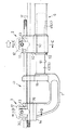
図1ないし図8に、この発明の緊張装置の実施例を示す。図1において、緊張装置は正面視がコ字形のフレーム1とフレーム1の右端外側に配置した第1チャック2と、フレーム1の左端上部に配置した第2チャック3と、第1チャック2を左右動自在に支持するスライダー4およびガイド5と、ガイド5の下方にガイド5と平行に配置した操作器6、および第2チャック3に組み込んだストッパー7などで構成する。
【0012】
図3ないし図5において、第1チャック2は断面L字形の鋼ブロックからなる固定ブロック10と、固定ブロック10の上面に配置されて前後スライドする可動ブロック11と、可動ブロック11を固定ブロック10に対して押し付け操作する挟持操作具12、および固定ブロック10の前端上面に固定したねじブラケット13などで構成する。
固定ブロック10の後部上面に挟持壁14を立設し、その前側面の上部に水平の挟持溝15を形成し、下部に挟持溝15と平行な通し溝16を形成する。挟持溝15は断面半円状の溝からなり、その内面にねじ山からなる突起17の一群を形成する。挟持壁14と対向する可動ブロック11の後面壁にも、挟持溝15と同様の挟持溝15を形成し、これら一対の挟持溝15、15でワイヤロープWを前後に挟持固定する(図4参照)。通し溝16は断面優弧円状の溝からなり、ワイヤロープWを相対移動自在に案内支持する。
【0013】
可動ブロック11は断面逆L字形の鋼ブロックからなり、その下面に左右一対の脚片19を突設し、脚片19の中央部に前後貫通状の穴20を形成する。可動ブロック11を前後スライド自在に支持するために、固定ブロック10の上面左右に、脚片19を収容する前後に長い溝21を凹み形成する。さらに、挟持壁14の後面下部から各溝21を前後に縦通する状態でガイド軸22をねじ込み固定し、その軸部23で脚片19の穴21を支持する。これにより、可動ブロック11は溝21の範囲内で軸部23に沿って前後スライドでき、穴20の後部開口縁とガイド軸22との間に配置した圧縮コイル型のばね24で挟持壁14から遠ざかる側へ移動付勢される。
【0014】
ねじブラケット13は左右横長の凸字形の鋼ブロックからなり、固定ブロック10の上面前縁に配置して、左右両側を図示していないボルトで固定ブロック10に締結固定する。ねじブラケット13の左右中央にねじ穴26を前後貫通状に形成する。このねじ穴26に挟持操作具12をねじ込んで、可動ブロック11を挟持操作具12でスライド操作する。挟持操作具12は、ねじ軸27の一端に操作ノブ28を固定してなり、ねじ軸27の突端を可動ブロック11の前側面に接当させる。操作ノブ28を時計回転方向へ回転操作することによって、可動ブロック11をばね24に抗して挟持壁14の側へ接近移動でき、逆方向へ回転操作することによって挟持壁14から遠ざかる側へ移動できる。
【0015】
第2チャック3も基本的には第1チャック2と同じ構造とされる。詳しくは、図6ないし図8に示すように、固定ブロック29で可動ブロック30を前後スライド自在に支持し、可動ブロック30上にねじブラケット13を固定する。さらに、固定ブロック29に可動ブロック30の脚片19を収容する溝21を設け、この溝21内において脚片19をガイド軸22の軸部23で案内支持し、図示していないばねで可動ブロック30の全体を挟持壁14から離れる側へ移動付勢する。
【0016】
第2チャック3の固定ブロック29が第1チャック2の固定ブロック10と異る点は、挟持壁14の上部に通し溝16を形成し、その下部に挟持溝15を形成した点と、通し溝16がJ字状の溝からなり、その上面が解放されている点と、通し溝16の一側端の上部にワイヤロープWの上面を保持する保持爪部48を突設した点である。可動ブロック30にもJ字状の通し溝16と挟持溝15を同様に形成する。他は第1チャック2と同じであるので、同一部材に同一符号を符してその説明を省略する。
【0017】
第2チャック3の可動ブロック30には、ワイヤロープWを緊張操作するとき、引締め操作したロープが緩む側へ戻るのを防ぐストッパー7を設ける。そのために、可動ブロック30の左右中央にテーブル状の支持壁31を設け、その中央に軸受穴32を上下貫通状に通設する。
ストッパー7は円板状のカム体33と、カム体33の上下面に突設した偏心軸(軸)34とを一体に設けた旋削品からなり、下方の偏心軸34を上記の軸受穴32で支持し、上方の偏心軸34を、可動ブロック30の上端面にねじで締結固定した軸受ブロック35の軸受穴36で支持する。さらに軸受ブロック35とカム体33の間に配置したねじりコイル形のばね37で、カム板33を偏心軸34を中心にして反時計回転方向へ回動付勢する。これにより、カム体33はその周面が第1チャック2で引締め操作されるワイヤロープWの移動軌跡に入り込む向きへ回動する傾向を生じ、ワイヤロープWを固定ブロック29の通し溝16に押し付ける。この状態でワイヤロープWが緩む側へ移動すると、カム体33はワイヤロープWの周面にさらに強力に喰い込むので、ワイヤロープWを固定できる。逆にワイヤロープWが引締め操作されるときは、カム体33の周面が通し溝16から遠ざかる側へ回動するので、ワイヤロープWはカム体33と通し溝16との間を支障なく通過できる。
【0018】
カム体33の下面には、偏心軸34と同心状の円弧溝38を形成し、これに規制ピン39を係合する。規制ぴん39は支持壁31に打ち込んで固定する。カム体33は円弧溝38の形成範囲内でのみ回動でき、カム体33がワイヤロープWに外接していないときの回動限界を規制ピン39と円弧溝38とで規制している。なお、ストッパー7は、下方の偏心軸34に装着した止め輪40で上方への移動が規制されている。
【0019】
図2において、第2チャック3の固定ブロック29はフレーム1に設けた受台1aに締結固定し、第1チャック2の固定ブロック10はスライダー5に締結固定する。これにより、両チャック2、3の通し溝16および挟持溝15の中心軸は、同一垂直平面上に位置し、第1チャック2は丸軸からなるガイド5の範囲内で左右移動できる。フレーム1の、第1チャック2側の端には上下に長いホルダー1bを立設し、その上部にワイヤロープWの通過を許すU字溝1cを形成する。このホルダー1bと第2チャック3との間を装填部41にして、両者1b、3間に位置する上下のワイヤロープWにクランプ筒42を外嵌装着する。クランプ筒42は断面長円状のアルミニウム筒体からなり、その全体を押し潰すことにより、ワイヤロープWの始終端を固定できる。
【0020】
操作器6としては、油圧シリンダやエアシリンダなどの流体圧シリンダを適用でき、より大きな操作力を出力できる油圧シリンダが好ましい。操作器6はばねリターン式のシングルアクションシリンダーであって、ピストンロッド43の突端をフレーム1のホルダー1bに取付ボス44を介して締結固定し、シリンダー本体45の側端をブラケット46を介してスライダー4に締結固定する。これにより、シリンダー本体45はホルダー1bに対して接離移動でき、ホルダー1bから離れる側へ移動するときに第1チャック2を同行移動させて、第1チャック2で挟持固定ワイヤロープWを引締め操作する。符号47は作動油の出入り口である。
【0021】
なお、この実施例の緊張装置に適用されるワイヤロープWの呼び寸法は9mmであり、その破断強度は約5トンである。また、緊張装置で出力される緊張力は1トンであり、そのときワイヤロープWに作用する応力は100kg/cm以上である。シリンダー本体45が待機位置にあるときの緊張装置の左右長は50cm弱であり、全体重量は2.6kg前後である。
【0022】
次にラッシングを行う場合について、緊張装置の使い方を説明する。まず、ワイヤロープWにクランプ筒42を通し、ワイヤロープWを繰り出して固縛しようとする荷物に巻掛ける。このとき、荷物の角に木片等の当て物を置いて、荷物を保護する。ワイヤロープWの始終端をクランプ筒42に通した後、両チャック2、3にセットし、クランプ筒42を装填部41に位置させる。この状態で各チャック2、3の挟持操作具12をそれぞれ操作して、一方のロ−プ端を第2チャック3の可動ブロック30と固定ブロック29で挟持固定し、他方のロープ端を第1チャック2の固定ブロック10および可動ブロック11で挟持固定する。このようにワイヤロープWを各チャック2、3で挟持固定した状態において、各通し溝16の対向間隔はロープ径より大きいので、通し溝16内においてワイヤロープWが拘束されることはない。ストッパー7は固定ブロック29側の通し溝16と協同してワイヤロープWを前後に挟んでいる。
【0023】
上記の状態で操作器6を作動させて、第1チャック2を第2チャック3から離れる側へ移動させることにより、ワイヤロープWが引締め操作される。固縛対象によっては、操作器6を1回作動させるだけで十分な緊張力が得られるが、ワイヤロープWの巻掛け長が大きい場合には、第1チャック2を繰り返えし往復させて、緊張力を除々に増加する。挟持操作具12を緩めて待機位置へ戻し、ワイヤロープWを固定および可動の両ブロック10、11で再び挟持固定した後、操作器6を作動させてワイヤロープWを引き締め操作するのである。
【0024】
第1チャック2を待機位置へ戻すとき、ワイヤロープWはストッパー7によって引締め状態が保持されている。ワイヤロープWが緩む側へ移動すると、これに同行してカム体33が回動し、この回動量分だけカム体33の周面がロープ表面に喰い込む。従って、ワイヤロープ23は通し溝16とカム体33とに挟持固定されて、緩み方向への移動が拘束されるのである。一方、ワイヤロープWが再度緊張操作される場合には、カム体33と通し溝16の間隔が広がる向きにカム体33が回動するので、ワイヤロープWは支障なく通し溝16を通過できる。ワイヤロープWの緊張力が所定値に達した段階で、クランプ筒42を油圧操作式のかしめ具で押し潰して塑性変形させ、ワイヤロープWの始終端を固定する。この後、両チャック2、3の可動ブロック11、30を後退させて緊張装置をワイヤロープWから分離し、第1チャック2の側において、ワイヤロープWの巻掛け終端をカッターで切断して作業を終了する。
【0025】
この発明の緊張装置は、上記の実施例の一部を図9ないし図12に示すように変更して実施することができる。そこでは、L字状のフレ−ム1の一端に受台1aを固定し、他端に固定したホルダ―1bに操作器6を取り付ける。操作器6はスライダー4およびガイド5を兼ねるよう構成する。詳しくは、ピストンロッド43の突設をホルダ―1bにねじ込み固定して、ガイド5を兼ねる。さらに、図10に示すように、シリンダ−本体45の端部上面に、第1チャック2を締結固定するための受台50を一体に設け、スライダー4を兼ねる。ピストンロッド43の下面にはコ字形断面のガイド溝51を形成し、この溝51と係合するピン52をシリンダ−本体45の端栓に植設する。これは、シリンダ−本体45が左右移動するとき、ピストンロッド43の回りに回動するのを防ぐためである。ピストンロッド43は内端が開口する円筒軸状に形成してあり、その内端寄りの周面にピストンを一体に形成する。
【0026】
第1チャック2は、上記の実施例と同様に、固定ブロック10、可動ブロック11、挟持操作具12、およびねじブラケット13などで構成する。異る点は、可動ブロック11の下端を軸53で前後揺動自在に支持し、可動ブロック11を倍力機構として構成する点にある。その中途部の後面に挟持溝15と通し溝16を形成し、揺動先端の前面にねじ軸27の突端を接当させて、ねじ軸27から受ける押圧力を増幅してワイヤ−ロ−プWに作用させるのである。この場合のばね24は、捻りコイルばねで形成する。
【0027】
第2チャック3の可動ブロック30も同様に倍力機構として構成する。その下端部を軸53で前後揺動自在に支持し、後面中途部に通し溝16と挟持溝15をそれぞれ設け、揺動先端の前面にねじ軸27の突端を接当させるのである。可動ブロック30は、捻りコイル形のばね24でワイヤ−ロ−プWから離れる向きへ付勢する。
【0028】
ストッパ−7は、固定ブロック29の側に配置した2個のカム体33、33と、可動ブロック30の側に配置した1個のカム体33とからなり、各カム体33を偏心軸34で回転自在に支持し、ねじりコイル形のばね37で締り勝手に回動付勢する。固定ブロック29側の偏心軸34の上端は、固定ブロック29締結される軸受ブロック54で軸支する。図12に示すように、3個のカム体33はワイヤ−ロ−プWを挟んで二等辺三角形の頂部を占める状態で配置してある。この配置形態を採ることによって、ロ−プ中心軸が蛇行するようなクランプ力を作用させて、ワイヤ−ロ−プWをより強固に固定保持できる。ワイヤ−ロ−プWが第1チャック2で引締め操作される場合には、上記の実施例のカム体33と同様に緩み回動できる。上記以外の構造については、先の実施例の部材と同等の部材に同じ符号を付して、その説明を省略する。
【0029】
以上のように、スライダー4およびガイド5を操作器6で兼ねる形態を採ると、構造を簡素化して緊張装置の製造に要するコストを減少できる。スライダー4およびガイド5を省略できる分だけ重量を減らし、緊張装置の取扱いを容易化することもできる。
【0030】
上記以外に、緊張装置の一部を次のように変更して実施することができる。第2チャック3を第1チャック2と同様にスライダー4で支持し、操作器6で引締め操作できるようにする。この場合は、第1チャック2にもストッパー7を設ける。
操作器6としては、流体圧シリンダ以外に、モータおよび減速器を介して回転駆動されるねじ軸と、このねじ軸で往復操作されるナット体を操作要素とする、機械式の操作器6を用いることができる。
ストッパー7は、ワイヤロープWを前後から挟持する一対のカム体33で構成することができる。円板状のカム体33に代えて、ラチェット爪状のレバーを用いてストッパー7を構成できる。ストッパー7は固定ブロック29の側や、ホルダー壁1bなどに設けることができ、要は引き締め操作されるワイヤロープWの移動軌道に臨む任意個所に設けることができる。
【0031】
挟持操作具12は、小形の油圧シリンダーで構成することができ、必ずしもねじを締め付け要素とする必要はない。
挟持溝15に形成する突起17は、ねじで形成する以外に溝中心軸と交差する浅い溝間の突起やリブ、あるいはダイヤ模様状の突起群などで形成できる。挟持溝15の内面に半硬質のプラスチック片を固定して、ワイヤロープWに対する摩擦抵抗を増加しても良い。
フレーム1の適当個所に、操作器6への作動油の供給を制御するスイッチを設け、このスイッチからの出力信号に基ずいて電磁式のコントロールバルブを作動させ、操作器6を制御することができる。さらに、ワイヤロープWの緊張力を表示するための表示器をフレーム1の適所に設けることができる。
クランプ筒42は、断面C字状に形成してあってもよい。
【図面の簡単な説明】
【図1】緊張装置の原理説明図である。
【図2】図2(a)は緊張装置の平面図、図2(b)はその正面図である。
【図3】第1チャックの平面図である。
【図4】図3におけるA−A線断面図である。
【図5】第1チャックの分解斜視図である。
【図6】第2チャックの平面図である。
【図7】図6におけるB−B線断面図である。
【図8】第2チャックの分解斜視図である。
【図9】緊張装置の別の実施例を示す正面図である。
【図10】図9におけるC−C線断面図である。
【図11】図9におけるD−D線断面図である。
【図12】図11におけるE−E線断面図である。
【符号の説明】
1………フレ−ム、2………第1チャック、3………第2チャック、
4………スライダー、5………ガイド、6………操作器、7………ストッパ−、
10………固定ブロック、11………可動ブロック、12………挟持操作具,
15………挟持溝、16………通し溝、29………固定ブロック、
30………可動ブロック、33………カム体、34………偏心軸、
37………ばね、41………装填部、42………クランプ筒、
W………ワイヤ−ロ−プ
[0001]
[Industrial application fields]
The present invention relates to a tension device for a wire rope, which is used when packing large luggage or securing luggage (hereinafter simply referred to as lashing) to prevent collapse of a ship or the like.
[0002]
[Prior art]
In conventional lashing work using wire rope as a lashing material, various lashing brackets such as turnbuckles, shackles, and clips are indispensable, and a series of operations such as rope tightening and lashing are performed manually. . Therefore, work efficiency is low, and material costs and labor costs required for lashing work are high. Skilled and specialized workers are indispensable for the work, so that, for example, when work is urgent, sufficient personnel may not be secured.
[0003]
In order to streamline the lashing work, a work system using a steel belt as a lashing material has been proposed, and the lashing work system using a wire rope is being devoured. In this case, work equipment for securing and fixing the steel belt by tensioning is enriched, so that the lashing work can be performed relatively easily and the material cost can be reduced.
This type of tensioning device is known from, for example, Japanese Patent Publication No. 1-32087 and Japanese Patent Application Laid-Open No. 5-229508.
[0004]
[Problems to be solved by the invention]
In a lashing operation using a steel belt as a lashing material, it is necessary to avoid twisting the middle part of the belt wrapped around the load. For this reason, careful attention must be paid to the belt wrapping, which complicates the work. For example, when connecting stacked steel plate coils with a series of steel belts, a winding pattern that does not twist the belt must be selected.
As mentioned above, wire ropes are still used for securing a group of loads connected by steel belts to the hull and for reinforcing lashing during voyage, and two types of lashing materials must be handled. There is still room for improvement.
[0005]
An object of the present invention is to provide a tension device for a wire rope that is suitable for automatically tensioning a wire rope wound around a luggage or the like and fixing a rope end with a clamp cylinder.
Another object of the present invention is to provide a tension device for a hand-held wire rope suitable for performing a lashing operation inside a container or a cargo hold.
Another object of the present invention is to provide a tension device for a wire rope that can efficiently perform a lashing operation and a packing operation at a work site with a small amount of labor and a material cost required for the operation.
[0006]
[Means for Solving the Problems]
The tensioning device of the present invention includes a frame 1 and a pair of first chuck 2 and second chuck 3 that are disposed at both ends of the frame 1 and clamp and fix one end and the other end of the wire rope W, respectively.
The frame 1 is provided with a slider 4 for supporting at least one of the chucks 2 and 3 and a guide 5 for guiding and supporting the slider 4 so as to reciprocate.
An operation device 6 is provided between the frame 1 and the slider 4 for moving one chuck 2 away from the other chuck 3.
A stopper 7 is provided to allow the wire rope W to move in the tension direction but to prevent the wire rope W from moving in the slack direction while facing the movement trajectory of the wire rope W to be tightened.
A loading portion 41 for mounting the clamp cylinder 42 is provided between the chucks 2 and 3.
[0007]
Specifically, the operating device 6 is constituted by an operating cylinder having a cylinder body 45 that also serves as the slider 4 and a piston rod 43 that also serves as the guide 5 and has one end fixed to the frame 1. -The first chuck 2 is fixed to the main body 45, and the second chuck 3 is fixed to the frame 1.
Both chucks 2 and 3 are fixed blocks 10 and 29, a movable block 11 that is detachably supported by the fixed blocks 10 and 29, and the movable blocks 11 and 30 are in contact with the fixed blocks 10 and 29. It is comprised by the clamping operation tools 12 and 12 which carry out separation operation. Clamping grooves 15 and 15 for clamping and fixing the wire rope W and through grooves 16 and 16 allowing relative movement of the wire rope W are provided on the opposing surfaces of the fixed blocks 10 and 29 and the movable blocks 11 and 30, respectively.
A cam body 33 in which the stopper 7 is disposed facing the through groove 16 of at least one chuck 3, a shaft 34 that supports the cam body 33 so as to be able to project and retract with respect to the through groove 16, and the cam body 33 through the through groove 16. It consists of a spring 37 that urges and advances toward.
Each of the holding grooves 15 and 15 is formed by a groove having a partial arc cross section, and a protrusion 17 that increases the frictional resistance against the wire rope W is formed on the inner surface of each groove.
Each of the chucks 2 and 3 is composed of a fixed block 10 and 29 and a movable block 11 and 30 whose one ends are swingably supported by shafts 53 and 53 with respect to the fixed blocks 10 and 29. A sandwiching groove 15 and a through groove 16 are formed in the middle part of both movable blocks 11, 30, and the operation ends of the sandwiching operation tools 12, 12 are connected to the swinging tips of both movable blocks 11, 30.
[0008]
[Action]
In use, one of the first chuck 2 and the second chuck 3 holds the winding start end of the wire rope W wound around the object to be secured, and the other end holds and fixes the winding end of the wire rope W. A clamp cylinder 42 is disposed in the loading portion 41 between the chucks 2 and 3, and a winding start end and a winding end are inserted through the clamp cylinder 42 in advance. In this state, the operating device 6 is operated, for example, the first chuck 2 on the winding end side is moved along the guide 5 and the wire rope W is tightened. Next, the clamping force of the first chuck 2 is released and returned to the standby position before tightening. After the wire rope W is clamped and fixed again, the operation device 6 is operated to tighten the wire rope W. Is repeated to apply a predetermined tension to the wire rope W. Finally, the clamp cylinder 42 is plastically deformed to fix the winding start end of the wire rope W. While the first chuck 2 is returned to the standby position and the wire rope W is re-fixed, the stopper 7 captures and fixes the wire rope W and keeps the tensioned state.
[0009]
As described above, in the tensioning device of the present invention, the wire rope W can be automatically tightened by the mechanical force of the operating device 6 including a fluid pressure cylinder. Since no skill is required for setting the wire rope W to the tensioning device or for operating the tensioning device, anyone can easily perform the lashing work with the wire rope W and perform lashing work with fewer personnel. The material required for the lashing operation can be basically limited to the wire rope W and the clamp cylinder 42.
According to the tensioning device in which the slider 4 serves as the cylinder body 45 and the piston rod 43 serves as the guide 5, the overall weight can be reduced and the rope tensioning operation can be performed easily. It also helps to simplify the structure and reduce manufacturing costs. According to the chuck structure in which the movable blocks 11 and 30 are swingably supported and the swinging tips are pressed by the sandwiching operation tool 12, the wire rope W can be firmly sandwiched by the boosting action.
[0010]
【The invention's effect】
In the tensioning device of the present invention, the wire rope W can be used as a tying material, and the tightening operation can be automatically performed by mechanical force. Therefore, packing and lashing operations can be efficiently performed with less effort and steel. Compared to the case where a belt is used as a lashing material, the lashing strength can be increased and the work reliability can be improved. When the wire rope W is wound around the load, the restriction on the pattern can be eliminated. Since the material cost required for the lashing work and the human cost can be reduced, the cost of the lashing work can be reduced as a whole.
Since the pair of chucks 2 and 3 clamp and fix the winding start and end of the wire rope W and at least one of them is slid by the operating device 6 to tighten the wire rope W, the operator can use the frame of the tensioning device. Therefore, even if it is a narrow space inside the container or in the cargo hold, if there is a space that allows the operator to enter, the lashing operation can be performed without any trouble.
[0011]
【Example】
1 to 8 show an embodiment of the tensioning device of the present invention. In FIG. 1, the tensioning device includes a frame 1 that is U-shaped in front view, a first chuck 2 that is disposed outside the right end of the frame 1, a second chuck 3 that is disposed at the upper left end of the frame 1, and the first chuck 2. The slider 4 and the guide 5 that are movably supported, the operation device 6 disposed below the guide 5 in parallel with the guide 5, the stopper 7 incorporated in the second chuck 3, and the like.
[0012]
3 to 5, the first chuck 2 includes a fixed block 10 made of a steel block having an L-shaped cross section, a movable block 11 that is disposed on the upper surface of the fixed block 10 and slides back and forth, and the movable block 11 is fixed to the fixed block 10. A clamping operation tool 12 that is pressed against the screw and a screw bracket 13 fixed to the upper surface of the front end of the fixed block 10 are configured.
A clamping wall 14 is erected on the rear upper surface of the fixed block 10, a horizontal clamping groove 15 is formed at the upper part of the front side surface, and a through groove 16 parallel to the clamping groove 15 is formed at the lower part. The clamping groove 15 is a groove having a semicircular cross section, and forms a group of protrusions 17 formed of threads on the inner surface thereof. A pinch groove 15 similar to the pinch groove 15 is also formed on the rear surface wall of the movable block 11 facing the pinch wall 14, and the wire rope W is pinched and fixed by these pair of pinch grooves 15, 15 (see FIG. 4). ). The through groove 16 is a groove having a circular arc with a cross section, and guides and supports the wire rope W so as to be relatively movable.
[0013]
The movable block 11 is made of a steel block having an inverted L-shaped cross section, and a pair of left and right leg pieces 19 project from the lower surface thereof, and a front and rear through hole 20 is formed at the center of the leg piece 19. In order to support the movable block 11 so as to be slidable back and forth, long grooves 21 are formed in the left and right sides of the upper surface of the fixed block 10 before and after the leg pieces 19 are accommodated. Further, the guide shaft 22 is screwed and fixed in a state where each groove 21 is vertically passed from the lower rear surface of the sandwiching wall 14, and the hole 21 of the leg piece 19 is supported by the shaft portion 23. As a result, the movable block 11 can slide back and forth along the shaft portion 23 within the range of the groove 21, and can be separated from the holding wall 14 by the compression coil spring 24 disposed between the rear opening edge of the hole 20 and the guide shaft 22. It is energized to move away.
[0014]
The screw bracket 13 is composed of left and right horizontally-convex steel blocks, and is arranged on the upper front edge of the fixed block 10, and the left and right sides are fastened and fixed to the fixed block 10 with bolts (not shown). A screw hole 26 is formed through the front and rear of the screw bracket 13 at the center of the left and right. The clamping operation tool 12 is screwed into the screw hole 26 and the movable block 11 is slid with the clamping operation tool 12. The sandwiching operation tool 12 has an operation knob 28 fixed to one end of the screw shaft 27, and the projecting end of the screw shaft 27 is brought into contact with the front side surface of the movable block 11. By rotating the operation knob 28 in the clockwise direction, the movable block 11 can be moved closer to the holding wall 14 against the spring 24, and moved in the opposite direction to move away from the holding wall 14. it can.
[0015]
The second chuck 3 has basically the same structure as the first chuck 2. Specifically, as shown in FIGS. 6 to 8, the movable block 30 is slidably supported by the fixed block 29 and the screw bracket 13 is fixed on the movable block 30. Further, a groove 21 for receiving the leg piece 19 of the movable block 30 is provided in the fixed block 29, and the leg piece 19 is guided and supported by the shaft portion 23 of the guide shaft 22 in the groove 21, and the movable block is supported by a spring (not shown). The whole 30 is urged to move to the side away from the holding wall 14.
[0016]
The fixing block 29 of the second chuck 3 is different from the fixing block 10 of the first chuck 2 in that the through groove 16 is formed in the upper part of the holding wall 14 and the holding groove 15 is formed in the lower part thereof. Reference numeral 16 denotes a J-shaped groove, the upper surface of which is open, and the point that a holding claw portion 48 for holding the upper surface of the wire rope W protrudes from the upper portion of one side end of the through groove 16. A J-shaped through groove 16 and a holding groove 15 are similarly formed in the movable block 30. The other parts are the same as those of the first chuck 2, and the same members are denoted by the same reference numerals and the description thereof is omitted.
[0017]
The movable block 30 of the second chuck 3 is provided with a stopper 7 that prevents the tightened rope from returning to the loosening side when the wire rope W is tensioned. For this purpose, a table-like support wall 31 is provided in the center of the left and right of the movable block 30, and a bearing hole 32 is passed through in the center in the vertical direction.
The stopper 7 is a turning product in which a disc-shaped cam body 33 and an eccentric shaft (shaft) 34 projecting from the upper and lower surfaces of the cam body 33 are integrally provided. The lower eccentric shaft 34 is connected to the bearing hole 32 described above. The upper eccentric shaft 34 is supported by a bearing hole 36 of a bearing block 35 that is fastened and fixed to the upper end surface of the movable block 30 with a screw. Further, a torsion coil spring 37 disposed between the bearing block 35 and the cam body 33 urges the cam plate 33 to rotate counterclockwise about the eccentric shaft 34. As a result, the cam body 33 tends to rotate in a direction in which the peripheral surface enters the movement locus of the wire rope W tightened by the first chuck 2, and presses the wire rope W against the through groove 16 of the fixed block 29. . When the wire rope W moves to the loose side in this state, the cam body 33 bites into the peripheral surface of the wire rope W more strongly, so that the wire rope W can be fixed. On the contrary, when the wire rope W is tightened, the peripheral surface of the cam body 33 rotates to the side away from the through groove 16, so that the wire rope W passes between the cam body 33 and the through groove 16 without any trouble. it can.
[0018]
An arc groove 38 concentric with the eccentric shaft 34 is formed on the lower surface of the cam body 33, and a restriction pin 39 is engaged with the arc groove 38. The regulation pin 39 is driven into the support wall 31 and fixed. The cam body 33 can rotate only within the formation range of the arc groove 38, and the limit of rotation when the cam body 33 is not circumscribed by the wire rope W is regulated by the regulation pin 39 and the arc groove 38. The stopper 7 is restricted from moving upward by a retaining ring 40 attached to the lower eccentric shaft 34.
[0019]
In FIG. 2, the fixed block 29 of the second chuck 3 is fastened and fixed to a cradle 1 a provided on the frame 1, and the fixed block 10 of the first chuck 2 is fastened and fixed to the slider 5. Thereby, the central axes of the through grooves 16 and the holding grooves 15 of both chucks 2 and 3 are located on the same vertical plane, and the first chuck 2 can move left and right within the range of the guide 5 formed of a round shaft. At the end of the frame 1 on the first chuck 2 side, a vertically long holder 1b is erected, and a U-shaped groove 1c that allows the wire rope W to pass therethrough is formed on the upper portion. A space between the holder 1b and the second chuck 3 is used as a loading portion 41, and a clamp cylinder 42 is externally attached to the upper and lower wire ropes W located between the both 1b and 3. The clamp cylinder 42 is made of an aluminum cylinder having an elliptical cross section, and the start and end of the wire rope W can be fixed by crushing the entire cylinder.
[0020]
As the operating device 6, a hydraulic cylinder such as a hydraulic cylinder or an air cylinder can be applied, and a hydraulic cylinder capable of outputting a larger operating force is preferable. The operating device 6 is a spring return type single action cylinder, in which the protruding end of the piston rod 43 is fastened and fixed to the holder 1b of the frame 1 via the mounting boss 44, and the side end of the cylinder body 45 is fixed to the slider via the bracket 46. Fasten to 4 and fix. As a result, the cylinder body 45 can move toward and away from the holder 1b. When the cylinder body 45 moves away from the holder 1b, the first chuck 2 is moved along with the first chuck 2, and the clamping wire rope W is tightened by the first chuck 2. To do. Reference numeral 47 is an inlet / outlet of hydraulic oil.
[0021]
In addition, the nominal dimension of the wire rope W applied to the tension device of this embodiment is 9 mm, and its breaking strength is about 5 tons. Moreover, the tension | tensile_strength output by a tension apparatus is 1 ton, and the stress which acts on the wire rope W at that time is 100 kg / cm < 2 > or more. The left and right length of the tensioning device when the cylinder body 45 is in the standby position is a little less than 50 cm, and the overall weight is about 2.6 kg.
[0022]
Next, how to use the tensioning device will be described for lashing. First, the clamp cylinder 42 is passed through the wire rope W, and the wire rope W is drawn out and wound around a load to be secured. At this time, a piece of wood or the like is placed on the corner of the luggage to protect the luggage. After passing the start and end of the wire rope W through the clamp cylinder 42, the wire rope W is set on both chucks 2 and 3, and the clamp cylinder 42 is positioned on the loading portion 41. In this state, the clamping operation tool 12 of each chuck 2 and 3 is operated to clamp and fix one rope end between the movable block 30 and the fixed block 29 of the second chuck 3 and the other rope end to the first. The chuck 2 is clamped and fixed by the fixed block 10 and the movable block 11. Thus, in a state where the wire rope W is clamped and fixed by the chucks 2 and 3, the opposing spacing of the through grooves 16 is larger than the rope diameter, and therefore the wire rope W is not restrained in the through grooves 16. The stopper 7 cooperates with the through groove 16 on the fixed block 29 side to sandwich the wire rope W in the front-rear direction.
[0023]
The wire rope W is tightened by operating the operating device 6 in the above state and moving the first chuck 2 away from the second chuck 3. Depending on the object to be secured, sufficient tension can be obtained by operating the operating device 6 only once. However, when the winding length of the wire rope W is large, the first chuck 2 is repeatedly moved back and forth. , Gradually increase the tension. After the clamping operation tool 12 is loosened and returned to the standby position and the wire rope W is clamped and fixed again by both the fixed and movable blocks 10 and 11, the operating device 6 is operated to tighten the wire rope W.
[0024]
When the first chuck 2 is returned to the standby position, the wire rope W is held in a tightened state by the stopper 7. When the wire rope W moves to the loosening side, the cam body 33 rotates along with the wire rope W, and the circumferential surface of the cam body 33 bites into the rope surface by the amount of rotation. Therefore, the wire rope 23 is clamped and fixed between the through groove 16 and the cam body 33, and the movement in the loosening direction is restricted. On the other hand, when the wire rope W is tensioned again, the cam body 33 rotates in the direction in which the gap between the cam body 33 and the through groove 16 is widened, so that the wire rope W can pass through the through groove 16 without any problem. When the tension of the wire rope W reaches a predetermined value, the clamp cylinder 42 is crushed and plastically deformed by a hydraulically operated caulking tool, and the start and end of the wire rope W are fixed. Thereafter, the movable blocks 11 and 30 of both chucks 2 and 3 are retracted to separate the tensioning device from the wire rope W, and the winding end of the wire rope W is cut with a cutter on the first chuck 2 side. Exit.
[0025]
The tensioning device of the present invention can be implemented by changing a part of the above-described embodiment as shown in FIGS. There, the cradle 1a is fixed to one end of the L-shaped frame 1, and the operating device 6 is attached to the holder 1b fixed to the other end. The operation device 6 is configured to serve as both the slider 4 and the guide 5. Specifically, the protrusion of the piston rod 43 is screwed and fixed to the holder 1b to serve also as the guide 5. Further, as shown in FIG. 10, a receiving base 50 for fastening and fixing the first chuck 2 is integrally provided on the upper surface of the end of the cylinder body 45, and also serves as the slider 4. A guide groove 51 having a U-shaped cross section is formed on the lower surface of the piston rod 43, and a pin 52 that engages with the groove 51 is implanted in the end plug of the cylinder body 45. This is to prevent the cylinder body 45 from rotating around the piston rod 43 when moving from side to side. The piston rod 43 is formed in a cylindrical shaft shape whose inner end is open, and a piston is integrally formed on a peripheral surface near the inner end.
[0026]
The first chuck 2 includes a fixed block 10, a movable block 11, a clamping operation tool 12, a screw bracket 13, and the like, as in the above embodiment. The difference is that the lower end of the movable block 11 is supported by a shaft 53 so as to be swingable back and forth, and the movable block 11 is configured as a booster mechanism. A pinch groove 15 and a through groove 16 are formed on the rear surface of the middle portion, and the protruding end of the screw shaft 27 is brought into contact with the front surface of the rocking tip to amplify the pressing force received from the screw shaft 27 and to perform wire rope. It acts on W. In this case, the spring 24 is formed of a torsion coil spring.
[0027]
The movable block 30 of the second chuck 3 is similarly configured as a booster mechanism. The lower end thereof is supported by a shaft 53 so as to be able to swing back and forth, and a through groove 16 and a holding groove 15 are provided in the middle part of the rear surface, and the protruding end of the screw shaft 27 is brought into contact with the front surface of the swing tip. The movable block 30 is urged away from the wire rope W by a torsion coil spring 24.
[0028]
The stopper 7 is composed of two cam bodies 33, 33 arranged on the fixed block 29 side and one cam body 33 arranged on the movable block 30 side. It is supported so that it can rotate freely and is urged to rotate by a torsion coil spring 37. The upper end of the eccentric shaft 34 on the fixed block 29 side is supported by a bearing block 54 fastened to the fixed block 29. As shown in FIG. 12, the three cam bodies 33 are arranged in a state of occupying the top of an isosceles triangle with the wire rope W interposed therebetween. By adopting this arrangement, the wire rope W can be more firmly fixed and held by applying a clamping force that causes the center axis of the rope to meander. When the wire rope W is tightened by the first chuck 2, the wire rope W can be loosely turned in the same manner as the cam body 33 of the above embodiment. About the structure other than the above, the same code | symbol is attached | subjected to the member equivalent to the member of a previous Example, and the description is abbreviate | omitted.
[0029]
As described above, adopting a form in which the slider 4 and the guide 5 are combined with the operating device 6 can simplify the structure and reduce the cost required for manufacturing the tensioning device. The weight can be reduced by the amount that the slider 4 and the guide 5 can be omitted, and the handling of the tensioning device can be facilitated.
[0030]
In addition to the above, a part of the tensioning device can be changed as follows. Similarly to the first chuck 2, the second chuck 3 is supported by the slider 4 and can be tightened by the operation device 6. In this case, a stopper 7 is also provided on the first chuck 2.
As the operating device 6, in addition to the fluid pressure cylinder, a mechanical operating device 6 having a screw shaft that is rotationally driven through a motor and a speed reducer and a nut body that is reciprocated by the screw shaft as operating elements. Can be used.
The stopper 7 can be composed of a pair of cam bodies 33 that sandwich the wire rope W from the front and rear. Instead of the disc-shaped cam body 33, the stopper 7 can be configured using a ratchet claw-shaped lever. The stopper 7 can be provided on the side of the fixed block 29, the holder wall 1b, or the like. In short, the stopper 7 can be provided at an arbitrary position facing the moving track of the wire rope W to be tightened.
[0031]
The clamping operation tool 12 can be constituted by a small hydraulic cylinder and does not necessarily have to be a screw as a fastening element.
The protrusions 17 formed in the sandwiching grooves 15 can be formed by protrusions or ribs between shallow grooves intersecting the groove center axis, a diamond pattern-like protrusion group, or the like, in addition to being formed by screws. A frictional resistance against the wire rope W may be increased by fixing a semi-rigid plastic piece to the inner surface of the holding groove 15.
A switch for controlling the supply of hydraulic oil to the operating device 6 is provided at an appropriate position of the frame 1, and an electromagnetic control valve is operated based on an output signal from the switch to control the operating device 6. it can. Furthermore, an indicator for displaying the tension of the wire rope W can be provided at an appropriate position on the frame 1.
The clamp cylinder 42 may be formed in a C-shaped cross section.
[Brief description of the drawings]
FIG. 1 is a diagram illustrating the principle of a tensioning device.
FIG. 2 (a) is a plan view of the tensioning device, and FIG. 2 (b) is a front view thereof.
FIG. 3 is a plan view of the first chuck.
4 is a cross-sectional view taken along line AA in FIG.
FIG. 5 is an exploded perspective view of the first chuck.
FIG. 6 is a plan view of a second chuck.
7 is a cross-sectional view taken along line BB in FIG.
FIG. 8 is an exploded perspective view of a second chuck.
FIG. 9 is a front view showing another embodiment of the tensioning device.
10 is a cross-sectional view taken along line CC in FIG. 9. FIG.
11 is a cross-sectional view taken along line DD in FIG. 9. FIG.
12 is a cross-sectional view taken along line EE in FIG.
[Explanation of symbols]
1 ... Frame, 2 ... First chuck, 3 ... Second chuck,
4 .... Slider, 5 .... Guide, 6 .... Operator, 7 .... Stopper,
10 ......... fixed block, 11 ......... movable block, 12 .....
15 ......... Clamping groove, 16 ......... Through groove, 29 ......... Fixed block,
30 ......... Moveable block, 33 ......... Cam body, 34 ......... Eccentric shaft,
37 ......... Spring, 41 ......... Loading part, 42 ......... Clamp cylinder,
W ......... Wire rope

Claims (6)

フレーム1と、フレーム1の両端に配置されて、ワイヤロープWの一端および他端側をそれぞれ挟持固定する一対の第1チャック2および第2チャック3を備えており、
フレーム1に前記両チャック2、3の少なくともいずれか一方を支持するスライダー4と、このスライダー4を往復動自在に案内支持するガイド5とが設けられており、
フレーム1とスライダー4との間に、一方のチャック2を他方のチャック3から遠ざかる側へ移動操作する操作器6が設けられており、
引き締め操作されるワイヤロープWの移動軌跡に臨んで、ワイヤロープWの緊張方向への移動は許すが、緩み方向への移動は阻止するストッパー7が設けられており、
両チャック2、3の間に、クランプ筒42を装着するための装填部41が設けてあるワイヤロープ用の緊張装置。
A frame 1 and a pair of first chuck 2 and second chuck 3 which are disposed at both ends of the frame 1 and sandwich and fix one end and the other end of the wire rope W, respectively.
The frame 1 is provided with a slider 4 for supporting at least one of the chucks 2 and 3 and a guide 5 for guiding and supporting the slider 4 so as to reciprocate.
An operating device 6 is provided between the frame 1 and the slider 4 for moving one chuck 2 away from the other chuck 3.
A stopper 7 is provided to allow the wire rope W to move in the tension direction but to prevent the wire rope W from moving in the loosening direction, facing the movement trajectory of the wire rope W to be tightened.
A tension device for a wire rope in which a loading portion 41 for mounting a clamp cylinder 42 is provided between both chucks 2 and 3.
操作器6が、スライダー4を兼ねるシリンダ−本体45と、ガイド5を兼ねて一端がフレ−ム1に固定してあるピストンロッド43とを有する操作シリンダ−からなり、シリンダ−本体45に第1チャック2を固定し、フレ−ム1に第2チャック3が固定してある請求項1記載のワイヤロープ用の緊張装置。The operating device 6 comprises an operating cylinder having a cylinder body 45 that also serves as the slider 4 and a piston rod 43 that also serves as the guide 5 and is fixed to the frame 1 at one end. The tension device for a wire rope according to claim 1, wherein the chuck 2 is fixed, and the second chuck 3 is fixed to the frame 1. 両チャック2、3のそれぞれが、固定ブロック10、29と、固定ブロック10、29に対して接離自在に支持した可動ブロック11、30と、可動ブロック11、30を固定ブロック10、29に対して接離操作する挟持操作具12、12を備えており、
固定ブロック10、29と可動ブロック11、30の対向面のそれぞれに、ワイヤロープWを挟持固定する挟持溝15、15と、ワイヤロープWの相対移動を許す通し溝16、16が設けられている請求項1、または2記載のワイヤロープ用の緊張装置。
Both chucks 2 and 3 are fixed blocks 10 and 29, movable blocks 11 and 30 supported so as to be able to contact with and separate from fixed blocks 10 and 29, and movable blocks 11 and 30 are fixed to fixed blocks 10 and 29. Are equipped with clamping operation tools 12, 12 for making contact and separation operations.
Clamping grooves 15 and 15 for clamping and fixing the wire rope W and through grooves 16 and 16 allowing relative movement of the wire rope W are provided on the opposing surfaces of the fixed blocks 10 and 29 and the movable blocks 11 and 30, respectively. The tension device for wire ropes according to claim 1 or 2.
ストッパー7が、少なくとも一方のチャック3の通し溝16に臨んで配置したカム体33と、カム体33を通し溝16に対して出没旋回自在に支持する軸34と、カム体33を通し溝16へ向って進出付勢するばね37とを備えている請求項1、2、または3記載のワイヤロープ用の緊張装置。The stopper 7 has a cam body 33 disposed facing the through groove 16 of at least one chuck 3, a shaft 34 that supports the cam body 33 so as to be able to protrude and retract with respect to the through groove 16, and the cam body 33 through the through groove 16. The tension device for a wire rope according to claim 1, 2 or 3, further comprising: a spring 37 that advances and urges toward the side. 挟持溝15、15のそれぞれが部分円弧断面状の溝からなり、各溝の溝内面にワイヤロープWに対する摩擦抵抗を増加する突起17が形成してある請求項3または4記載のワイヤロープ用の緊張装置。The wire rope for a wire rope according to claim 3 or 4, wherein each of the holding grooves (15, 15) comprises a groove having a partial arc cross-sectional shape, and a protrusion (17) that increases frictional resistance against the wire rope (W) is formed on the inner surface of each groove. Tension device. 両チャック2、3のそれぞれが、固定ブロック10、29と、各固定ブロック10、29に対して一端が軸53、53で揺動自在に支持された可動ブロック11、30とを含み、両可動ブロック11、30の中途部に挟持溝15および通し溝16が形成され、両可動ブロック11、30の揺動先端寄りに挟持操作具12、12の操作端が連接してある請求項3、4、または5記載のワイヤロープ用の緊張装置。Each of the chucks 2 and 3 includes fixed blocks 10 and 29, and movable blocks 11 and 30 having one ends swingably supported by shafts 53 and 53 with respect to the fixed blocks 10 and 29. 5. A holding groove 15 and a through groove 16 are formed in the middle of the blocks 11 and 30, and the operation ends of the holding operation tools 12 and 12 are connected to the movable tips 11 and 30 near the swinging tip. Or a tensioning device for a wire rope according to claim 5.
JP20524595A 1995-07-19 1995-07-19 Tension device for wire rope Expired - Fee Related JP3671072B2 (en)

Priority Applications (1)

Application Number Priority Date Filing Date Title
JP20524595A JP3671072B2 (en) 1995-07-19 1995-07-19 Tension device for wire rope

Applications Claiming Priority (1)

Application Number Priority Date Filing Date Title
JP20524595A JP3671072B2 (en) 1995-07-19 1995-07-19 Tension device for wire rope

Publications (2)

Publication Number Publication Date
JPH0932888A JPH0932888A (en) 1997-02-04
JP3671072B2 true JP3671072B2 (en) 2005-07-13

Family

ID=16503801

Family Applications (1)

Application Number Title Priority Date Filing Date
JP20524595A Expired - Fee Related JP3671072B2 (en) 1995-07-19 1995-07-19 Tension device for wire rope

Country Status (1)

Country Link
JP (1) JP3671072B2 (en)

Families Citing this family (5)

* Cited by examiner, † Cited by third party
Publication number Priority date Publication date Assignee Title
CN102530294A (en) * 2012-02-29 2012-07-04 秦皇岛西重所燕大重型机械研究院有限公司 End clamping and tightening device for metal tape
CN105239818B (en) * 2015-10-30 2017-08-11 国网山东省电力公司东营供电公司 Telegraph pole guy fastens cylinder
CN112678244B (en) * 2020-12-15 2023-04-14 东莞市明骏智能科技有限公司 Binding apparatus is used in waterproofing membrane production
CN113602520B (en) * 2021-07-27 2023-03-14 中航西安飞机工业集团股份有限公司 Flexible large-span weak-rigidity light component overturning device and using method
CN114544337B (en) * 2022-01-13 2023-12-01 马鞍山法尔盛科技有限公司 Be used for wire rope tensile properties test to detect machine

Also Published As

Publication number Publication date
JPH0932888A (en) 1997-02-04

Similar Documents

Publication Publication Date Title
JP3487377B2 (en) Article packing device using plastic band
US3169560A (en) Binder strap tool
US4566378A (en) Apparatus for hooping a fiber bale in a fiber bale press
US3939762A (en) Apparatus for bundling firewood
US4655264A (en) Twist tying machine
US6363689B1 (en) Banding machine
US3633633A (en) Strapping apparatus
EP2430262B1 (en) Machine for binding reinforcement bars
JP3671072B2 (en) Tension device for wire rope
DE19826305A1 (en) Seat belt for placing around vehicle occupant
US7748415B2 (en) Plastic band tightening device with improved cutting mechanism
JPH0755690B2 (en) Packing tape feeding / tensioning device
US6568159B2 (en) Strapping packing machine
US4559977A (en) Twist tying machine
JPH02109814A (en) Drawing and sealing machine for packaging band made of synthetic resin
WO2022066000A1 (en) System and method for tying a knot
US3220338A (en) Package binding system
JP2000238711A (en) Dispenser with looper
US5326080A (en) Apparatus for tightening bands, in particular bands as fitted to furniture frames
GB1563022A (en) Tensioning device for chains and other lashings having eyelet-links
US3672295A (en) Strapping machine
JP2613454B2 (en) Multi-band banding method by reducing the tightening force
US20240025585A1 (en) Clamping assembly
US4932641A (en) Variable force exerting clamp assembly having a variable clamping area
SU1101382A1 (en) Apparatus for tying-up a stack of articles with tape

Legal Events

Date Code Title Description
A711 Notification of change in applicant

Free format text: JAPANESE INTERMEDIATE CODE: A711

Effective date: 20040426

RD02 Notification of acceptance of power of attorney

Free format text: JAPANESE INTERMEDIATE CODE: A7422

Effective date: 20040426

A521 Written amendment

Free format text: JAPANESE INTERMEDIATE CODE: A821

Effective date: 20040426

TRDD Decision of grant or rejection written
A01 Written decision to grant a patent or to grant a registration (utility model)

Free format text: JAPANESE INTERMEDIATE CODE: A01

Effective date: 20050322

A61 First payment of annual fees (during grant procedure)

Free format text: JAPANESE INTERMEDIATE CODE: A61

Effective date: 20050418

R150 Certificate of patent or registration of utility model

Free format text: JAPANESE INTERMEDIATE CODE: R150

FPAY Renewal fee payment (event date is renewal date of database)

Free format text: PAYMENT UNTIL: 20090422

Year of fee payment: 4

FPAY Renewal fee payment (event date is renewal date of database)

Free format text: PAYMENT UNTIL: 20090422

Year of fee payment: 4

FPAY Renewal fee payment (event date is renewal date of database)

Free format text: PAYMENT UNTIL: 20100422

Year of fee payment: 5

FPAY Renewal fee payment (event date is renewal date of database)

Free format text: PAYMENT UNTIL: 20110422

Year of fee payment: 6

FPAY Renewal fee payment (event date is renewal date of database)

Free format text: PAYMENT UNTIL: 20120422

Year of fee payment: 7

FPAY Renewal fee payment (event date is renewal date of database)

Free format text: PAYMENT UNTIL: 20120422

Year of fee payment: 7

FPAY Renewal fee payment (event date is renewal date of database)

Free format text: PAYMENT UNTIL: 20130422

Year of fee payment: 8

FPAY Renewal fee payment (event date is renewal date of database)

Free format text: PAYMENT UNTIL: 20140422

Year of fee payment: 9

LAPS Cancellation because of no payment of annual fees