JP3671044B2 - Massage treatment machine - Google Patents
Massage treatment machine Download PDFInfo
- Publication number
- JP3671044B2 JP3671044B2 JP2003060433A JP2003060433A JP3671044B2 JP 3671044 B2 JP3671044 B2 JP 3671044B2 JP 2003060433 A JP2003060433 A JP 2003060433A JP 2003060433 A JP2003060433 A JP 2003060433A JP 3671044 B2 JP3671044 B2 JP 3671044B2
- Authority
- JP
- Japan
- Prior art keywords
- far
- treatment machine
- massage
- massage treatment
- infrared
- Prior art date
- Legal status (The legal status is an assumption and is not a legal conclusion. Google has not performed a legal analysis and makes no representation as to the accuracy of the status listed.)
- Expired - Fee Related
Links
Images


Description
【0001】
【発明の属する技術分野】
本発明は、マッサージ治療機に関し、特に、揉み玉を有し、かつ、磁気及び遠赤外線を発する押圧ローラが使用者の身体に密着して回転しながら患部を効果的にマッサージするマッサージ治療機に関する。
【0002】
【従来の技術】
従来、マッサージ治療機は、マットに押圧ローラや揉み玉が内蔵され、これら押圧ローラが使用者の身体に密着しながら回転することによりマッサージするタイプのものがある(特許文献1参照)。
また、肩こりや腰痛の解消法として磁石を身体のツボに貼る方法が用いられている。
【0003】
【特許文献1】
特開平05−317374号公報(第3頁、第6図)
【0004】
【発明が解決しようとする課題】
しかしながら、前述したマッサージ治療機の押圧ローラには身体のツボを押す作用がなく、揉み玉は身体を引張したり不快な痛みを伴うものが多いという問題点があった。
また、押圧ローラや揉み玉が直接当たらない患部については効果が得られないという問題点があった。
一方、磁石を身体のツボに貼る方法は効果的ではあるが、身体のツボに正確に磁石を貼ることは困難であるし、その位置を特定するのも面倒であった。
【0005】
そこで、使用者に不快な痛みを与えることなく、身体のツボや筋肉を刺激すると共に、磁気や遠赤外線による即効性を体感でき、心身共に満足できるマッサージ治療機の提供が強く望まれていた。
本発明は、上記問題点を解決するためになされたものであって、その目的とするところは、使用者に不快な痛みを与えることなく身体を外部から刺激し、磁気と遠赤外線を用いて身体を内部から刺激することによって、従来と比べてマッサージの効果を著しく向上させたマッサージ治療機を提供することである。
また、本発明のマッサージ治療機では、足マッサージ機や手持ち式の温熱治療機を設けて身体を横臥させた状態で全身をマッサージすることを目的としている。
【0006】
【課題を解決するための手段】
本発明の請求項1記載のマッサージ治療機では、身体を横臥可能な本体に、押圧ローラを備える台車と、身体の屈曲に沿った形状のガイドレールと、前記台車を前記ガイドレールに摺動させながら移動させる電動モータと、が内設され、前記台車が移動する際に前記押圧ローラが身体に密着して回転するマッサージ治療機において、
前記押圧ローラの内部に遠赤外線ヒータが設けられ、
前記押圧ローラの表面に磁石が混合された複数の揉み玉が設けられると共に、この揉み玉に前記遠赤外線ヒータが設けられた空間と外部に連通した開口孔が設けられ、
前記本体に、遠赤外線ランプが内設された押圧部を備える手持ち式の温熱治療機が設けられ、
前記押圧部はセラミック製で、表面に前記遠赤外線ランプが設けられた空間と外部に連通した開口部が設けられることを特徴とする。
【0007】
請求項2記載の発明では、請求項1記載のマッサージ治療機において、前記本体に、身体を横臥させた状態の足の裏に突起を往復動させて衝打する足マッサージ機が設けられ、前記足マッサージ機は、水平方向位置調整可能に形成され、未使用時には前記マットの内部に格納可能に形成されることを特徴とする。
【0008】
請求項3記載の発明では、請求項1〜2のいずれかに記載のマッサージ治療機において、前記台車に遠赤外線シートが設けられていることを特徴とする。
【0009】
請求項4記載の発明では、請求項1〜3いずれか記載のマッサージ治療機において、前記磁石が混合された揉み玉に代えて、ゲルマニウム製の基材上に磁石を固定した揉み玉であって、遠赤外線の通過孔を備えた揉み玉を使用することを特徴とする。
【0010】
請求項5記載の発明では、請求項1〜4いずれか記載のマッサージ治療機において、前記本体の背当て部の少なくともローラの通過部分に沿ってヒータを配設したことを特徴とする。
【0011】
請求項6記載の発明では、請求項1〜5いずれかに記載のマッサージ治療機に、遠赤外線ヒータを内蔵した温熱マットを接続し、その温熱マットの表面にゲルマニウム製の基材上に磁石を固定した揉み玉であって、遠赤外線の通過孔を備えた揉み玉を多数配設したことを特徴とする。
【0012】
【発明の実施の形態】
以下、図面に基づいて本発明のマーサージ治療機の実施の形態を説明する。
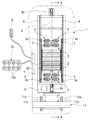
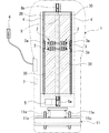
図1は本発明のマッサージ治療機の内部を説明する平面図、図2は図1のA−A線によるマッサージ治療機の断面図(一部側面)である。
【0013】
図1,2に示すように、本実施の形態のマッサージ治療機は、身体を横臥可能な本体としてのマット1(外形の二点鎖線にて図示)と、押圧ローラ2と、台車3と、ガイドレール4と、電動モータ5と、リモコン6と、電源ユニット7と、遠赤外線シート(一点鎖線で図示)8と、足マッサージ機11と、温熱治療機15と、を主要な構成としている。
【0014】
マット1は、ポリウレタンフォームなどの弾力性のある素材(図示せず)を包容して形成され、使用者の身体を横臥可能な幅と全長で外形を成している。
【0015】
台車3は、四隅に配置された車輪3aを身体の屈曲に沿って上下に並設されたガイドレール4に摺動させながら移動可能に形成され、台車3上の両端側にそれぞれ対を成して2箇所ずつ、合計8個の押圧ローラ2が設けられている。
前記台車3の中央部には複数本のニードルベアリング20が回転自在に設けられている。
さらに、台車3にはベルト9(二点鎖線で図示)が接続されると共に、このベルト9はピニオン9a,9bに連絡されると共に、前記ピニオン9aは電動モータ5の回転軸に接続されている。
【0016】
リモコン6は後述する遠赤外線ヒータ2j,3f、電動モータ5、電源ユニット7、遠赤外線シート8、足マッサージ機11、温熱治療機15にそれぞれ接続され、これらの動作を操作するためのものである。
【0017】
電源ユニット7は一般用家庭用電源100Vを電源とし、後述する遠赤外線ヒータ2j,3f、電動モータ5、遠赤外線シート8、足マッサージ機11、温熱治療機15にそれぞれ接続され電源を供給している。
前記遠赤外線シート8は、台車3の底面部に配置され、セラミック(図示せず)を加熱して遠赤外線を発生するものである。
【0018】
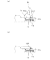
足マッサージ機11は使用者を横臥させた状態の足の裏をマッサージするためのものであって、図3(a)に示すように、突起11aが足の裏の踵と土踏まずに対応する位置に2箇所、両足で合計4箇所設けられ、この突起11aがソレノイド(図示せず)によって所定のリズムで水平方向に往復動することによって、足の裏を衝打するようになっている。
また、前記足マッサージ機11は台車11bの枢軸11fに回動自在に固定され、さらに、スプリング11cによって水平方向に付勢されている。
従って、足マッサージ機11の使用時は台車11bの車輪11dをレール11eに摺動させることにより使用者に合わせて水平方向位置調整可能となっている。
さらに、足マッサージ機11の未使用時には、図3(b)に示すように回動させてマット1内に格納できるようになっている。
【0019】
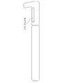
温熱治療機15は、図4に示すように、セラミック製で卵型に形成される押圧部15aが合計8箇所設けられ、この押圧部15aの内部は遠赤外線ランプ15bが設けられている。
また、前記押圧部15aの頂点位置には前記遠赤外線ランプ15bの設けられた空間と外部に連通した開口部15cが設けられている。
従って、温熱治療機15の使用時は、押圧部15aが熱せられてその表面から遠赤外線が放射され、さらに開口部15cを介して遠赤外線が放射されるため、この押圧部15aを使用者の腹部などの上方に直接当ててマッサージできるようになっている。
【0020】
次に、図5〜7に基づいて本実施の形態の押圧ローラ2について説明する。
なお、押圧ローラ2はニードルベアリング20を挟んだ状態で台車3の両側にそれぞれ対を成して2箇所ずつ、合計8個の押圧ローラ2が設けられているが、ここでは台車3の一方側に設けられた押圧ローラ2を図示して説明する。
図5は押圧ローラ2の平面図、図6は図5のB−B線による押圧ローラ2を示す図、図7は図5の矢視Cによる押圧ローラ2を示す図である。
【0021】
図5に示すように、押圧ローラ2は左右に対を成し、中央より上下対称位置にそれぞれ配置されている。
また、図6(a)に示すように、前記押圧ローラ2は3つの回転ローラ2a〜2cで構成されている。
前記回転ローラ2a〜2cはそれぞれ両端側に樹脂リング2dが嵌合されると共に、これら樹脂リング2dは内部に挿通されたローラシャフト2gに軸支されることによって、それぞれ独立して回転可能となっている。
【0022】
また、前記回転ローラ2a〜2cには磁石が混合した硬質プラスチックの揉み玉2hが複数個設けられている。
前記揉み玉2hは通称フェライトプラスチック磁石と呼ばれ、熱硬化性樹脂とフェライト粉末または希土類磁石粉末を混合して均一にした後、噴出成形して成型加工されたものである。
また、前記揉み玉2hには開口孔2iが設けられている。なお、開口孔2iは図中において二箇所のみ図示されているが、実際には回転ローラ2の中心から放射状に複数の個所に設けられている(図7参照)。
そして、前記ローラシャフト2gの中央内部には遠赤外線ヒータ2jが内設され、この遠赤外線ヒータ2jが設けられた空間はローラシャフト2gの開口部2kを介して揉み玉2hの開口孔2iと通じている。
【0023】
2lは前記ローラシャフト2gの開口部2kが上方となるように固定しているブラケットであって、上部ベース3bに固定されている。
さらに、前記上部ベース3bは下部ベース3cとピポット軸3dで軸支され、揺動自在に固定されている(図6(b)参照)。
なお、3eはダンパであって上部ベース3bと下部ベース3cとの四隅の衝突を避けるためスプリングである。
また、前記下部ベース3cの中央には、揉み玉2hと同一の素材で形成され、かつ、遠赤外線ヒータ3fが内設された遠赤外線機10が配置されている。
【0024】
続いて、本実施の形態のマッサージ治療機の動作を説明する。
使用者がマット1の上に横臥してマッサージ治療機をリモコン6で作動させると、押圧ローラ2の遠赤外線ヒータ2j、遠赤外線機10の遠赤外線ヒータ3f、遠赤外線シート8から遠赤外線が放射される。
なお、足マッサージ機11や温熱治療機15は適宜作動させ、足マッサージ機11で足の裏をマッサージしたり、温熱治療機15の揉み玉15aを使用者の上方の部位、例えば腹部や胸部に直接当ててマッサージする。
【0025】
次に、電動モータ5を作動させるとピニオン9aが回転駆動し、ベルト9を介して台車3がガイドレール2に沿って摺動しながら所定速度で往復移動を繰り返す。
このとき、台車3の両端部に設けられた押圧ローラ2はそれぞれ台車3とピポット軸3dで揺動自在となっているため、常に押圧ローラ2の揉み玉2hが身体に密着しながら回転移動する。
【0026】
前記押圧ローラ2は使用者の身体に密着して回転する際に、押圧ローラ2の揉み玉2hが身体のツボを刺激すると共に、揉み玉2hの開口孔2iとローラシャフト2gの開口部2kとが一致して遠赤外線ヒータ2jの遠赤外線が身体に直接放射されるようになっている。
【0027】
さらに、揉み玉2hの周囲には磁石による磁場が形成され、台車3がガイドレール4の両端を左右に往復移動する際に様々な身体のツボに作用している。
なお、台車3が使用者の臀部下方に位置する場合は、ニードルベアリング20が臀部に密着して回転するため、身体の屈曲が台車3の移動の妨げにならないようになっている。
【0028】
従って、本実施の形態のマッサージ治療機にあっては、複数の揉み玉2hが身体を次々とテンポ良く押圧し、身体のツボや筋肉に刺激を与えることができる。
【0029】
さらに、回転ローラ2a〜2cがそれぞれ独立して回転することにより、様々な身体のツボを数多く押圧することができる。
【0030】
また、ローラシャフト2gの開口部2kが上方に開口しているため、常に遠赤外線ヒータ2jの遠赤外線が上方に向かって放射され、回転してくる揉み玉2hの開口孔2iを通じて身体に遠赤外線が効率的に伝わる。
遠赤外線機10によって、遠赤外線の効果に即効性を持たせることができる。
足マッサージ機11や温熱治療機15を併用することにより、使用者はマット1に横臥した状態で足の裏や腹部などの上方の部位も同時にマッサージできる。
【0031】
次に、実施の形態2に係るマッサージ治療機について説明する。
本実施の形態の説明において、前記実施の形態1と同一の構成要素については同一の符号を付してその説明は省略する。
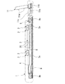
実施の形態2のマッサージ治療機は図9に示すように、身体を横臥可能な本体としてのマット1(外形の二点鎖線にて図示)と、押圧ローラ2と、台車3と、ガイドレール4と、電動モータ5と、リモコン6と、電源ユニット7と、足マッサージ機11を主要な構成としている。
前記実施の形態1では8個の押圧ローラを、4個づつ2連に分けて配置したが、本実施の形態では、それを1連として、台車3の幅を狭くし、さらに、背当て部にヒータ30を配設した構成である。
【0032】
前記ヒータ30は図9中斜線部分で示されるところであり、本体の左右に1枚づつ、合計2枚の板状ヒータ30によって構成され、それらのヒータ30は台車3の下側に配置され、台車3(ローラ2)の移動部分の全長に渡って配設されている。内部には電熱線が備えられ、荷電により、表面の板状セラミックを加熱して遠赤外線を放出させるしくみとなっている。
このように、背当て部分にヒータ30を配設することにより、揉み玉2hからの遠赤外線効果に加えて、背当て部全体から遠赤外線による暖熱効果が得られる。
台車が1連となっているので、患部にスポットを当てることが可能となり、また、背面ヒータからの遠赤外線が遮られずに十分に照射される。
【0033】
次に図10〜図12に基づいて実施の形態3に係るマッサージ治療機を説明する。
実施の形態3に係るマッサージ治療機は、前記実施の形態1、2のマッサージ治療機の揉み玉2hに代えて、ゲルマニウム製の円盤31上に磁石32を固定した揉み玉2mを使用したものである。
本発明に用いるゲルマニウムとしては無機ゲルマニウムや、有機ゲルマニウム(例えば、炭素2〜10個を含む有機ゲルマニウム錯体)を初め、ゲルマニウムを含むものが適用できるが、純度99%以上の無機ゲルマニウムが好ましい。
ゲルマニウムは肩こり、腰痛、筋肉痛などを解消する鎮痛効果や消炎効果を有している。
【0034】
前記ゲルマニウム製の円盤31の大きさは一例として直径2〜4cm、厚さ5〜6mmであり、円盤31の中央には雌ねじ孔33が貫通している。この雌ねじ孔33に磁石32の雄ねじ34がねじ込まれて固定されている。
前記磁石32は半球型の頭部35と、そこから突設した雄ねじ34によって略きのこ型に構成され、雄ねじ34がゲルマニウム製の円盤31の雌ねじ孔33に固着するようになっている。
また、磁石のねじ軸の中心を貫通して孔36が形成され、この孔36を通過して遠赤外線が放出されるようになっている。
また、孔36の先端は六角に形成されて締め付け工具の挿入孔となっている。
【0035】
この揉み玉2mをローラ2に装着する際には、先端の磁石32はN極、S極を交互に隣り合わせた状態で並べ、磁石32同士の磁力線が通過しながらマッサージ効果を発揮するようにする。
また、前記実施の形態で説明した足マッサージ機11の突起11aとしてこの揉み玉2mを使用することも可能である。
揉み玉2mの固定方法としては接着剤、あるいは取付金具等により、任意の方法により押圧ローラ2上または足マッサージ機11に固定する。
【0036】
ここで、前記揉み玉2h、2mにトルマリンを含有させることも可能である。
このトルマリンは、電気石とも呼ばれるように、その結晶の両端には電極が生じて、マイナスイオンを発する他、遠赤外線を発生し、また界面活性効果を有するなどの特性を持っている。
前記2h、2m全体をトルマリンとして、または内部にトルマリンの粉末を含有させることにより、患部にトルマリンから発生するマイナスイオンが働き、また、トルマリンの界面活性効果及び遠赤外線が患部に作用するようになる。
【0037】
次に、実施の形態4に係るマッサージ治療機を説明する。
実施の形態4のマッサージ治療機は、図13,14に示すような遠赤外線マット40を備えたものである。
この遠赤外線マット40はポリウレタンフォーム等の弾力性のある素材を包容して形成され、内部に遠赤外線を放出する面状のヒータ41を備えている。
表面の両端を除いた中央部分に全体に揉み玉2mが所定間隔で敷き詰められている。
この揉み玉2mは前記実施の形態3で説明したものであり、ゲルマニウム製(またはトルマリン)の円盤31上に磁石32を固定したものであり、先端の磁石32のN極とS極が交互に隣接している。
内部のヒータ41に荷電すると、面として全体が加熱され、遠赤外線の効果、ゲルマニウムの効果、磁力線による効果によりマッサージ効果が得られる。
または、トルマリンから発生するマイナスイオンが働き、また、トルマリンの界面活性効果及び遠赤外線が患部に作用するようになる。
マッサージ治療機には温熱治療機15と同様にコード42によって本体に接続されて、リモコンによって制御される。使用方法も同様に、揉み玉2m側を腹部などの上方に直接当ててマッサージを行う。
尚、この遠赤外線マット40は幅広として、全面に揉み玉2mを配置して、横臥した身体全体をカバーするマットレス等として使用することも可能である。
【0038】
次に、実施の形態5に係るマッサージ治療機を説明する。
実施の形態5のマッサージ治療機は、図15に示すような足マッサージ機50を備えたものである。
この足マッサージ機50は前記足マッサージ機11と同様に本体に横臥した状態で伸ばした足の裏をマッサージするものであって、図15に示すように、突起51が足の踵と土踏まずに対応する位置に左右2箇所、両足で4個設けられ、この突起51がソレノイドによるバイブレータ52によって所定のリズムで水平方向に往復動することによって、足の裏を衝打するようになっている。
また、足マッサージ機50の下は支持枠53内にレール上を移動可能に支持され、足マッサージ機50が足裏に当接するようにスプリングによって付勢されている。
そのため、本体に横臥して足をスプリングに抗して突起に当てて伸ばすと、突起51がスクリングによって足の裏を押圧し、バイブレータ52の作用によって足の裏をマッサージする。
本体への接続は、足が突起に当接するように、支持枠53を本体に接続するのであるが、その接続方法は取り付け具、バンド等により、任意の方法によって本体に固定する。
【0039】
また、突起51は台座54とその前面に配置された3個の磁石32によって構成されている。この磁石32は前記実施の形態3で説明したものと同一であり、半球型の頭部35と、そこから突設した雄ねじ34によって略きのこ型に構成されている。
そして、その雄ねじが台座54に固定され、3個の磁石が保持されている。
また、台座54は直径3〜4cm程度の円柱状であり、基部はソレノイドによるバイブレータ52に接続され、磁石32の台座54はトルマリンを含有した合成樹脂、あるいはゲルマニウムによって構成されている。
この、足マッサージ機50によって、トルマリン、磁石、ゲルマニウムの作用による優れたマッサージ効果が得られる。
【0040】
以上、本発明の実施の形態を説明してきたが、本発明の具体的構成は本実施の形態に限定されるものではなく、発明の要旨を逸脱しない範囲の設計変更などがあっても本発明に含まれる。
例えば、揉み玉2hの磁石と混合させる素材はプラスチック以外にセラミック、金属、ゴムなどの弾性体を用いても構わない。
押圧ローラ2、回転ローラ2a〜2c、揉み玉2h、遠赤外線機10の設置数は適宜設定することができる。
遠赤外線ヒータ2Jは遠赤外線を発するものであれば良く、これ以外に赤外線ランプなどを用いても良い。
【0041】
また、図8に示すように、足に位置する部分を取り外し可能な構造にして、内部にバイブレータを設けても良い。
【0042】
【発明の効果】
以上説明してきたように、本発明の請求項1記載のマッサージ治療機にあっては、上述したように構成したため、回転する押圧ローラの揉み玉による身体外部を刺激するマッサージと、磁気及び遠赤外線による身体内部を刺激するマッサージの両方を同時に行うことができ、従来と比べて身体を引張したり不快な痛みを伴うことなくマッサージの効果を体感することができる。
【0043】
遠赤外線ヒータの放射する遠赤外線によって身体の皮下深層の温度が上昇し、微細血管の拡張、血流循環の促進、代謝障害の一掃、組織の賦活、酵素生成促進などの様々な効果を得ることができる。
【0044】
揉み玉には磁石が混合されているため、押圧ローラが身体に沿ってマッサージする際に、揉み玉の周囲に形成される磁場が身体のツボを刺激し、微細血管の拡張、血流循環の促進の効果を得られる。
また、従来のように身体のツボを探して治療する必要がない。
【0045】
また、押圧ローラが台車にピポット軸で揺動自在に軸支されていることにより、マッサージ中に押圧ローラの揉み玉が使用者の身体に密着して効果的にマッサージすることができる。
【0046】
請求項2記載のマッサージ治療機にあっては、身体を横臥した状態で足マッサージ機を用いて足の裏をマッサージすることができる。
足マッサージ機は水平方向位置調整が可能であるため、使用者の足の裏にマッチする。
また、未使用時や運搬時には足マッサージ機を本体に格納してコンパクトにまとめることができる。
【0047】
請求項1記載のマッサージ治療機にあっては、身体を横臥した状態で温熱治療機を用いて腹部や胸部などをマッサージすることができる。
また、温熱治療機の押圧部に開口部が設けられることにより、遠赤外線が直接身体に放射され、遠赤外線による様々な効果が得られる。
【0048】
請求項3記載のマッサージ治療機にあっては、遠赤外線シートが身体の発汗作用を促し、汗腺から生体にたまった老廃物や、不要有害重金属、加工食品中の有害物、あるいは疲労や老化の原因である乳酸、遊離脂肪酸、脂肪、皮下脂肪、高血圧症の原因となる余分なナトリウム、疼痛の原因になる尿酸などを排泄させることができる。
また、身体をすばやく暖めて遠赤外線効果に即効性を持たせることができるという効果を奏する。
【0049】
請求項4記載のマッサージ治療機にあっては、ゲルマニウム製の基材上に磁石を固定した揉み玉であって、遠赤外線の通過孔を備えた揉み玉を使用する構成としたので、磁力線によるマッサージ効果に加え、ゲルマニウムによる肩こり、腰痛、筋肉痛などを解消する鎮痛効果や消炎効果が得られる。
【0050】
請求項5記載のマッサージ治療機にあっては、前記本体の背当て部の少なくともローラの通過部分に沿ってヒータを配設したので、背当て部全体から遠赤外線による暖熱効果が得られる。
【0051】
請求項6記載のマッサージ治療機にあっては、マッサージ治療機に、遠赤外線ヒータを内蔵した温熱マットを接続し、その温熱マットの表面にゲルマニウム製の基材上に磁石を固定した揉み玉であって、遠赤外線の通過孔を備えた揉み玉を多数配設したので、身体を横臥した状態で遠赤外線マットを用いて腹部や胸部などをマッサージすることができる。
そして、遠赤外線の効果、ゲルマニウムの効果、磁力線によるマッサージ効果が得られる。
【図面の簡単な説明】
【図1】 本発明の実施の形態のマッサージ治療機の内部を説明する平面図である。
【図2】 図1のA−A線によるマッサージ治療機の断面図(一部側面)である。
【図3】 足マッサージ機11の側面図(a)及び格納時の状態(b)を示す図である。
【図4】 温熱治療機15の側面図である。
【図5】 本実施の形態の台車3と押圧ローラ2を示す図である。
【図6】 図5のB−B線による押圧ローラ2を示す図である。
【図7】 図5の矢視Cによる押圧ローラ2を示す図である。
【図8】 その他の実施の形態を示す図である。
【図9】 実施の形態2に係るマッサージ治療機の内部を説明する平面図である。
【図10】 実施の形態3に係る揉み玉の斜視図である。
【図11】 実施の形態3に係る揉み玉の平面図である。
【図12】 実施の形態3に係る揉み玉のF−F断面図である。
【図13】 遠赤外線マットの平面図である。
【図14】 遠赤外線マットの側面図である。
【図15】 足マッサージ機の説明図である。
【符号の説明】
1 マット
2 押圧ローラ
2a、2b、2c 回転ローラ
2d 樹脂リング
2g ローラシャフト
2h 揉み玉
2i 開口孔
2j、3f 遠赤外線ヒータ
2k 開口部
2l ブラケット
2m 揉み玉
3 台車
3a 車輪
3b 上部ベース
3c 下部ベース
3d ピポット軸
3e ダンパ
4 ガイドレール
5 電動モータ
6 リモコン
7 電源ユニット
8 遠赤外線シート
9 ベルト
9a、9b ピニオン
10 遠赤外線機
11 足マッサージ機
11a 突起
11b 台車
11c スプリング
11d 車輪
11e レール
11f 枢軸
15 温熱治療機
15a 押圧部
15b 遠赤外線ランプ
15c 開口部
15a 押圧部
20 ニードルベアリング
30 ヒータ
31 円盤
32 磁石
33 雌ねじ孔
34 雄ねじ
35 頭部
36 孔
40 遠赤外線マット
41 ヒータ
42 コード
50 足マッサージ機
51 突起
52 バイブレータ
53 支持枠
54 台座[0001]
BACKGROUND OF THE INVENTION
The present invention relates to a massage treatment machine, and more particularly to a massage treatment machine that has massage balls and effectively massages an affected part while a pressing roller that emits magnetism and far infrared rays is in close contact with the user's body and rotates. .
[0002]
[Prior art]
2. Description of the Related Art Conventionally, there is a type of massage treatment machine in which a pressure roller and a kneading ball are built in a mat, and the pressure roller massages by rotating while closely contacting a user's body (see Patent Document 1).
In addition, as a method for relieving stiff shoulders and back pain, a method of sticking a magnet to the body's acupuncture point is used.
[0003]
[Patent Document 1]
JP 05-317374 A (
[0004]
[Problems to be solved by the invention]
However, the pressure roller of the massage treatment machine described above does not act to push the acupuncture points of the body, and the kneading balls have many problems that the body is pulled and unpleasant pain is accompanied.
In addition, there is a problem that the effect cannot be obtained for the affected part where the pressing roller and the kneading balls do not directly hit.
On the other hand, the method of sticking the magnet to the body acupuncture is effective, but it is difficult to accurately stick the magnet to the body acupoint, and it is troublesome to specify the position.
[0005]
Therefore, it has been strongly desired to provide a massage treatment machine that can stimulate the acupoints and muscles of the body without giving unpleasant pain to the user, and can feel the immediate effects of magnetism and far-infrared rays, and satisfy both mind and body.
The present invention has been made to solve the above-described problems, and the object of the present invention is to stimulate the body from the outside without causing unpleasant pain to the user, using magnetism and far infrared rays. The object of the present invention is to provide a massage treatment machine in which the effect of massage is remarkably improved as compared with the prior art by stimulating the body from the inside.
In addition, the massage treatment machine of the present invention is intended to massage the whole body in a state where the body is lying on its side by providing a foot massage machine or a hand-held thermotherapy machine.
[0006]
[Means for Solving the Problems]
In the massage treatment machine according to
A far-infrared heater is provided inside the pressing roller,
A plurality of kneading balls mixed with magnets are provided on the surface of the pressing roller, and the kneading balls are provided with an opening hole communicating with the space where the far infrared heater is provided, and the outside.
The main body is provided with a hand-held thermotherapy machine having a pressing portion in which a far-infrared lamp is installed,
The pressing portion is made of ceramic and has a space provided with the far-infrared lamp on the surface and an opening communicating with the outside.
[0007]
According to a second aspect of the present invention, in the massage treatment machine according to the first aspect, the main body is provided with a foot massage machine that reciprocates a protrusion on the sole of the foot in a state of lying down on the body, The foot massage machine is formed so that the position in the horizontal direction can be adjusted, and can be stored inside the mat when not in use.
[0008]
In invention of
[0009]
In invention of
[0010]
According to a fifth aspect of the present invention, in the massage treatment apparatus according to any one of the first to fourth aspects, a heater is disposed along at least a roller passing portion of the backrest portion of the main body.
[0011]
In invention of
[0012]
DETAILED DESCRIPTION OF THE INVENTION
Embodiments of the marsurge treatment device of the present invention will be described below with reference to the drawings.
FIG. 1 is a plan view for explaining the inside of the massage treatment machine of the present invention, and FIG. 2 is a cross-sectional view (partial side view) of the massage treatment machine along the line AA in FIG.
[0013]
As shown in FIGS. 1 and 2, the massage treatment machine according to the present embodiment includes a mat 1 (illustrated by a two-dot chain line in the outer shape), a
[0014]
The
[0015]
The
A plurality of
Further, a belt 9 (illustrated by a two-dot chain line) is connected to the
[0016]
The
[0017]
The
The far-
[0018]
The
The
Therefore, when the
Further, when the
[0019]
As shown in FIG. 4, the
In addition, an
Accordingly, when the
[0020]
Next, the
Note that a total of eight
5 is a plan view of the
[0021]
As shown in FIG. 5, the
Moreover, as shown to Fig.6 (a), the said
The
[0022]
The
The kneading
The kneading
A far-
[0023]
Reference numeral 2l denotes a bracket which is fixed so that the
Further, the
In the center of the
[0024]
Then, operation | movement of the massage treatment machine of this Embodiment is demonstrated.
When the user lies down on the
In addition, the
[0025]
Next, when the
At this time, since the
[0026]
When the
[0027]
Further, a magnetic field is formed around the kneading
When the
[0028]
Therefore, in the massage treatment machine according to the present embodiment, the plurality of kneading
[0029]
Furthermore, since the
[0030]
Further, since the
The far-
By using the
[0031]
Next, a massage treatment machine according to the second embodiment will be described.
In the description of the present embodiment, the same components as those in the first embodiment are denoted by the same reference numerals, and the description thereof is omitted.
As shown in FIG. 9, the massage treatment machine according to the second embodiment includes a mat 1 (illustrated by a two-dot chain line in the outer shape), a
In the first embodiment, the eight pressing rollers are divided into four groups of four, but in the present embodiment, this is used as a single station to reduce the width of the
[0032]
The
Thus, by providing the
Since the carriage is a single train, it is possible to apply a spot to the affected area, and far infrared rays from the rear heater are sufficiently irradiated without being blocked.
[0033]
Next, a massage treatment machine according to
The massage treatment machine according to the third embodiment uses a
As germanium used in the present invention, inorganic germanium and organic germanium (for example, an organic germanium complex containing 2 to 10 carbons) and germanium can be used, but inorganic germanium having a purity of 99% or more is preferable.
Germanium has an analgesic and anti-inflammatory effect that relieves stiff shoulders, back pain, muscle pain, and the like.
[0034]
The size of the
The
A
Further, the tip of the
[0035]
When the kneading
It is also possible to use the kneading
The kneading
[0036]
Here, it is also possible to contain tourmaline in the kneading
This tourmaline has characteristics such that, as it is called tourmaline, electrodes are generated at both ends of the crystal to emit negative ions, generate far-infrared rays, and have a surface-active effect.
By incorporating tourmaline powder in 2h and 2m as a whole, or containing tourmaline powder inside, negative ions generated from tourmaline act on the affected area, and the surface active effect of farmaline and far infrared rays act on the affected area. .
[0037]
Next, a massage treatment machine according to
The massage treatment machine according to
The far-
The kneading
This kneading
When the
Alternatively, negative ions generated from tourmaline act, and the surface active effect of farmaline and far infrared rays act on the affected area.
The massage treatment machine is connected to the main body by the
The far-
[0038]
Next, a massage treatment machine according to the fifth embodiment will be described.
The massage treatment machine according to the fifth embodiment includes a
This
The lower part of the
Therefore, when lying on the main body and extending the foot against the protrusion against the spring, the
The connection to the main body is such that the
[0039]
The
The male screw is fixed to the
The
The
[0040]
Although the embodiment of the present invention has been described above, the specific configuration of the present invention is not limited to the present embodiment, and the present invention can be applied even if there is a design change or the like without departing from the gist of the invention. include.
For example, the material to be mixed with the magnet of the kneading
The number of the
The far-infrared heater 2J only needs to emit far-infrared rays, and an infrared lamp or the like may be used in addition to this.
[0041]
Moreover, as shown in FIG. 8, you may make the structure which can remove the part located in a leg | foot, and may provide a vibrator inside.
[0042]
【The invention's effect】
As described above, since the massage treatment machine according to
[0043]
The far-infrared radiation emitted by the far-infrared heater increases the temperature of the body's subcutaneous deep layer, obtaining various effects such as dilation of microvessels, promotion of blood circulation, elimination of metabolic disorders, activation of tissues, and promotion of enzyme production. Can do.
[0044]
Since the kneading balls are mixed with magnets, when the pressure roller massages along the body, the magnetic field formed around the kneading balls stimulates the body's acupoints, dilates the fine blood vessels and prevents blood circulation. A promotion effect can be obtained.
Moreover, it is not necessary to search for acupoints on the body and treat them as in the past.
[0045]
Further, since the pressing roller is pivotally supported on the carriage by the pivot shaft, the massaging balls of the pressing roller can be in close contact with the user's body during the massage and can be effectively massaged.
[0046]
In the massage treatment machine according to
Since the foot massage machine can be adjusted in the horizontal direction, it matches the sole of the user's foot.
In addition, when not in use or transported, the foot massage machine can be stored in the main body for compact packaging.
[0047]
In the massage treatment machine according to the first aspect, the abdomen, the chest, and the like can be massaged using the thermal treatment machine in a state where the body is lying down.
Moreover, by providing an opening in the pressing portion of the thermal treatment machine, far infrared rays are directly emitted to the body, and various effects by the far infrared rays can be obtained.
[0048]
In the massage treatment machine according to
In addition, there is an effect that the body can be quickly warmed and the far infrared effect can be given immediate effect.
[0049]
In the massage treatment machine according to
[0050]
In the massage treatment machine according to
[0051]
In the massage treatment machine according to
And the effect of a far infrared ray, the effect of germanium, and the massage effect by a magnetic force line are acquired.
[Brief description of the drawings]
FIG. 1 is a plan view illustrating the inside of a massage treatment machine according to an embodiment of the present invention.
FIG. 2 is a cross-sectional view (partial side view) of the massage treatment machine along line AA in FIG. 1;
FIG. 3 is a side view of the
FIG. 4 is a side view of the
FIG. 5 is a diagram showing a
6 is a view showing the
7 is a view showing the
FIG. 8 is a diagram showing another embodiment.
FIG. 9 is a plan view for explaining the inside of the massage treatment machine according to the second embodiment.
10 is a perspective view of a kneading ball according to
11 is a plan view of a kneading ball according to
FIG. 12 is a cross-sectional view of the kneading balls taken along the line FF according to the third embodiment.
FIG. 13 is a plan view of a far-infrared mat.
FIG. 14 is a side view of a far-infrared mat.
FIG. 15 is an explanatory diagram of a foot massage machine.
[Explanation of symbols]
1
Claims (6)
前記押圧ローラの内部に遠赤外線ヒータが設けられ、
前記押圧ローラの表面に磁石が混合された複数の揉み玉が設けられると共に、この揉み玉に前記遠赤外線ヒータが設けられた空間と外部に連通した開口孔が設けられ、
前記本体に、遠赤外線ランプが内設された押圧部を備える手持ち式の温熱治療機が設けられ、
前記押圧部はセラミック製で、表面に前記遠赤外線ランプが設けられた空間と外部に連通した開口部が設けられることを特徴とするマッサージ治療機。A body having a pressing roller on a body capable of lying down on the body, a guide rail having a shape along the bending of the body, and an electric motor for moving the carriage while sliding on the guide rail, In the massage treatment machine in which the pressing roller rotates in close contact with the body when the carriage moves,
A far-infrared heater is provided inside the pressing roller,
A plurality of kneading balls mixed with magnets are provided on the surface of the pressing roller, and the kneading balls are provided with an opening hole communicating with the space where the far infrared heater is provided, and the outside.
The main body is provided with a hand-held thermotherapy machine having a pressing portion in which a far-infrared lamp is installed,
The massage treatment machine according to claim 1, wherein the pressing portion is made of ceramic and has a space provided with the far-infrared lamp on the surface and an opening communicating with the outside.
前記本体に、身体を横臥させた状態の足の裏に突起を往復動させて衝打する足マッサージ機が設けられ、
前記足マッサージ機は、水平方向位置調整可能に形成され、未使用時には前記マットの内部に格納可能に形成されることを特徴とするマッサージ治療機。The massage treatment machine according to claim 1,
The main body is provided with a foot massage machine for reciprocating the protrusion on the sole of the foot in a state where the body is lying on the back,
The foot massage machine is formed so that the position in the horizontal direction can be adjusted, and can be stored inside the mat when not in use.
前記台車に遠赤外線シートが設けられていることを特徴とするマッサージ治療機。In the massage treatment machine in any one of Claims 1-2,
A massage treatment machine, wherein a far-infrared sheet is provided on the carriage.
その温熱マットの表面にゲルマニウム製の基材上に磁石を固定した揉み玉であって、遠赤外線の通過孔を備えた揉み玉を多数配設したことを特徴とするマッサージ治療機。A heat treatment mat with a built-in far infrared heater is connected to the massage treatment machine according to claim 1,
A massage treatment machine characterized in that a number of kneading balls, each having a magnetium fixed on a base made of germanium, are provided on the surface of the thermal mat, and are provided with a far-infrared ray passage hole.
Priority Applications (2)
| Application Number | Priority Date | Filing Date | Title |
|---|---|---|---|
| JP2003060433A JP3671044B2 (en) | 2002-09-17 | 2003-03-06 | Massage treatment machine |
| KR1020030073503A KR20040079819A (en) | 2003-03-06 | 2003-10-21 | Massage machine |
Applications Claiming Priority (2)
| Application Number | Priority Date | Filing Date | Title |
|---|---|---|---|
| JP2002270556 | 2002-09-17 | ||
| JP2003060433A JP3671044B2 (en) | 2002-09-17 | 2003-03-06 | Massage treatment machine |
Publications (2)
| Publication Number | Publication Date |
|---|---|
| JP2004160154A JP2004160154A (en) | 2004-06-10 |
| JP3671044B2 true JP3671044B2 (en) | 2005-07-13 |
Family
ID=32827597
Family Applications (1)
| Application Number | Title | Priority Date | Filing Date |
|---|---|---|---|
| JP2003060433A Expired - Fee Related JP3671044B2 (en) | 2002-09-17 | 2003-03-06 | Massage treatment machine |
Country Status (1)
| Country | Link |
|---|---|
| JP (1) | JP3671044B2 (en) |
Families Citing this family (9)
| Publication number | Priority date | Publication date | Assignee | Title |
|---|---|---|---|---|
| KR100815095B1 (en) | 2004-05-28 | 2008-03-20 | 가부시키가이샤 닛폰 쇼쿠바이 | Transparent resin material |
| JP4638760B2 (en) * | 2004-11-02 | 2011-02-23 | 株式会社クマガワ | Health promotion tool |
| JP5487283B1 (en) * | 2012-12-05 | 2014-05-07 | 翔天電子實業有限公司 | Satsuma equipment |
| CN106563254A (en) * | 2016-10-18 | 2017-04-19 | 陈梦杰 | Auxiliary physiotherapy equipment for scapulobumeral periarthritis |
| CN109276428A (en) * | 2018-01-09 | 2019-01-29 | 厦门蒙发利电子有限公司 | A kind of massager core and massager |
| CN109954226B (en) * | 2019-04-18 | 2024-02-23 | 贝乐(广州)智能信息科技有限公司 | Neck massage instrument |
| CN113995642A (en) * | 2020-07-28 | 2022-02-01 | 章蓉 | Human body pressing device for simulating human hand pressing |
| CN113262147B (en) * | 2021-05-17 | 2022-07-01 | 何苗 | Clinical exercise and massage integrated rehabilitation device for cardiovascular internal medicine |
| CN115154145B (en) * | 2022-08-05 | 2023-10-20 | 董彩凤 | Acupuncture and moxibustion massage integrated treatment bed and use method thereof |
-
2003
- 2003-03-06 JP JP2003060433A patent/JP3671044B2/en not_active Expired - Fee Related
Also Published As
| Publication number | Publication date |
|---|---|
| JP2004160154A (en) | 2004-06-10 |
Similar Documents
| Publication | Publication Date | Title |
|---|---|---|
| KR101857555B1 (en) | Apparatus for physical therapy of bed type | |
| KR20090123029A (en) | A medical warmer of a bad type | |
| KR200408351Y1 (en) | The perineal region prostate curing apparatus | |
| JP3671044B2 (en) | Massage treatment machine | |
| CN110623833A (en) | Intelligent exercise massage chair | |
| CN208809003U (en) | Chinese medicine the five internal organs navel treats massage device | |
| KR20100002567A (en) | Functional massage apparatus | |
| KR20150001870U (en) | Multifunction frequency Heated Therapy | |
| CN108836786A (en) | A kind of intelligence Chinese physical therapy chair | |
| CN206026659U (en) | Foot massaging instrument | |
| KR20020075651A (en) | physical therapy bed | |
| CN201279260Y (en) | Multifunctional liquid crystal display massaging bed | |
| KR20040079819A (en) | Massage machine | |
| KR200197270Y1 (en) | The apparatus for thermotherapy | |
| KR100567191B1 (en) | The massage treatment machine | |
| CN207590938U (en) | A kind of massage pillow | |
| TWI236902B (en) | Massage therapy machine | |
| CN219921531U (en) | Neck fumigator | |
| KR200234830Y1 (en) | Spine treatment equipment | |
| CN216798061U (en) | Improved medical physiotherapy couch | |
| CN215740353U (en) | Circulation pressing type leg massager | |
| KR100531143B1 (en) | A rolling massage bed of using water | |
| KR200296464Y1 (en) | Movable type massage place that equip to all do cold wind and strong wind occurrence chapter | |
| KR101350625B1 (en) | A multi-purpose hand massager | |
| CN2933384Y (en) | Warm-heat physical therapeutic bed |
Legal Events
| Date | Code | Title | Description |
|---|---|---|---|
| A871 | Explanation of circumstances concerning accelerated examination |
Free format text: JAPANESE INTERMEDIATE CODE: A871 Effective date: 20040317 |
|
| A975 | Report on accelerated examination |
Free format text: JAPANESE INTERMEDIATE CODE: A971005 Effective date: 20040514 |
|
| A131 | Notification of reasons for refusal |
Free format text: JAPANESE INTERMEDIATE CODE: A131 Effective date: 20040525 |
|
| A521 | Written amendment |
Free format text: JAPANESE INTERMEDIATE CODE: A523 Effective date: 20040722 |
|
| A131 | Notification of reasons for refusal |
Free format text: JAPANESE INTERMEDIATE CODE: A131 Effective date: 20041019 |
|
| A521 | Written amendment |
Free format text: JAPANESE INTERMEDIATE CODE: A523 Effective date: 20041110 |
|
| TRDD | Decision of grant or rejection written | ||
| A01 | Written decision to grant a patent or to grant a registration (utility model) |
Free format text: JAPANESE INTERMEDIATE CODE: A01 Effective date: 20050405 |
|
| A61 | First payment of annual fees (during grant procedure) |
Free format text: JAPANESE INTERMEDIATE CODE: A61 Effective date: 20050415 |
|
| R150 | Certificate of patent (=grant) or registration of utility model |
Free format text: JAPANESE INTERMEDIATE CODE: R150 |
|
| LAPS | Cancellation because of no payment of annual fees |