JP3670497B2 - Adhesive applicator - Google Patents
Adhesive applicator Download PDFInfo
- Publication number
- JP3670497B2 JP3670497B2 JP32344598A JP32344598A JP3670497B2 JP 3670497 B2 JP3670497 B2 JP 3670497B2 JP 32344598 A JP32344598 A JP 32344598A JP 32344598 A JP32344598 A JP 32344598A JP 3670497 B2 JP3670497 B2 JP 3670497B2
- Authority
- JP
- Japan
- Prior art keywords
- adhesive
- shaft
- annular member
- shaft member
- annular
- Prior art date
- Legal status (The legal status is an assumption and is not a legal conclusion. Google has not performed a legal analysis and makes no representation as to the accuracy of the status listed.)
- Expired - Lifetime
Links
Images


Description
【0001】
【発明の属する技術分野】
本発明は、円環状部材用の接着剤塗布装置に関する。
【0002】
【従来の技術】
従来、孔部を有する円環状部材に接着剤を塗布する場合、円環状部材をバスケットに入れ、接着剤を収容した接着剤槽にバスケットごと円環状部材を浸漬し(いわゆる「どぶ付け」し)、バスケットを引き上げて余分な接着剤を円環状部材から液切りするという方法にて行われていた。
【0003】
【発明が解決しようとする課題】
しかしながら、上述の方法では、下記の問題を生じていた。
▲1▼ 液切りするための時間的ロスが生じる。
▲2▼ 均一で極薄い接着剤膜が理想的であるが、どぶ付けにより大量の接着剤が塗布されて接着剤膜が不均一となり、かつ、膜圧が厚くなってしまう。また、接着剤の無駄も多い。
▲3▼ 円環状部材の形状(例えば凹窪部を有する形状)によっては、接着剤が溜まったままの状態で乾燥し、不良品となる。
▲4▼ 接着剤槽にスラッジ等の汚れがある場合、その汚れが円環状部材表面に付着し、そのまま接着剤が乾燥してしまう。
▲5▼ 円環状部材同士あるいは円環状部材とバスケットとの接触部分では接着膜が歪に形成され、接着不良の原因となる。
▲6▼ バスケットごと接着剤槽に漬かるため、バスケットの後処理(接着剤の除去)が必要であり、手間を要する。
▲7▼ バスケットを昇降させる装置等により大がかりとなる。
【0004】
そこで、本発明は、上述の問題を解決して、作業能率が向上すると共に、高品質に仕上げることができる接着剤塗布装置を提供することを目的とする。
【0005】
【課題を解決するための手段】
上述の目的を達成するために、本発明に係る接着剤塗布装置は、中心に孔部を有する円環状部材に接着剤を塗布する装置であって、上記孔部に挿通されて複数個の上記円環状部材を相互に軸心所定間隔に吊持する軸本体を有する軸部材と、接着剤を収容した接着剤槽と、上記軸部材を回転可能に支持しつつ搬送して上記接着剤槽の接着剤液面に該軸部材を接近させて上記円環状部材の下部を該接着剤内へ浸漬させる搬送手段と、該搬送手段によって上記接着剤液面にまで接近した上記軸部材を回転させて該軸部材に吊持された上記円環状部材を連れ廻りさせる強制回転手段と、を備え、上記軸本体に軸心所定間隔に形成された複数の取付用凹周溝の夫々に、リング状の滑止め部材が外嵌され、該滑止め部材の外周面が、上記円環状部材を接触保持するように構成した。
【0006】
また、上記軸本体の取付用凹周溝の内側面と、上記滑止め部材の外周面とによって、円環状部材を保持する保持用凹周溝が、形成されている。
また、搬送手段が、平面的に見て平行に配設された2本のエンドレスチェーンと、該チェーンに所定ピッチで配設されて軸部材の両端近傍を着脱自在に支持する受け具と、を備えている。
【0007】
また、強制回転手段が、軸部材の一端側に設けられたピニオンギヤと、接着剤槽の接着剤液面に接近した高さ位置に設けられて上記ピニオンギヤと噛合するラック部材と、を備えている。
【0008】
【発明の実施の形態】
以下、実施の形態を示す図面に基づき、本発明を詳説する。
【0009】
図1と図2は、本発明の接着剤塗布装置の実施の一形態を示し、この接着剤塗布装置は、中心に孔部1aを有する円環状部材1に接着剤を塗布する装置であって、孔部1aに挿通されて円環状部材1を吊持する水平状軸部材2と、接着剤6を収容した上方開口状の接着剤槽3と、軸部材2を回転可能に支持しつつ搬送して接着剤槽3の接着剤液面6aに軸部材2を接近させて円環状部材1の下部を接着剤6内へ浸漬させる搬送手段4と、を備えている。円環状部材1の材質は例えば、金属やセラミック等が用いられる。
【0010】
ここで、図5と図7に示すように、円環状部材1は、中心に所定内径寸法φ1 の孔部1aを有すると共に、孔部1aの部分が凹部1bとされた円板形状である。
【0011】
しかして、本発明の接着剤塗布装置を具体的に説明すると、図1と図2と図8と図9に示すように、搬送手段4は、直方体型の上方開口状基台部12と、基台部12の凹所13にかつ平面的に見て平行に配設された左右2本のエンドレスチェーン8,8と、各チェーン8,8に所定ピッチで配設されて軸部材2の左右両端近傍を着脱自在に支持する複数個のコの字状受け具9…とを備え、左右のチェーン8,8は基台部12の左右側壁12a,12aに夫々取付けられた複数個のスプロケット14…に懸架されている。
【0012】
また、図3と図9に示す如く、基台部12の左右側壁12a,12aの上端縁15,15に於て、中間部よりもやや上流側Uには切欠部16が設けられている。この切欠部16は、上流側Uから下流側Dへ向かって下方へ傾斜する第1勾配面部17と、水平面部18と、上流側Uから下流側Dへ向かって上方へ傾斜する第2勾配面部19と、から成る。また、上記切欠部16,16を含む左右側壁12a,12aの上端縁15,15に沿って、チェーン8,8をガイドするガイド突条部20,20が付設されている。
【0013】
そして、スプロケット14…に懸架されたエンドレスチェーン8の上側は、上記ガイド突条部20に摺動自在に載置されており、スプロケット14を(図示省略の)駆動モータにて回転させることによって、チェーン8の上側をガイド突条部20に沿って上流側Uから下流側Dに摺動させるように構成している。なお、左右のチェーン8,8は同期機構等によって同一速度で移動する。
【0014】
また、図1〜図3に示すように、接着剤槽3は、上記基台部12の凹所13に、かつ、切欠部16に対応する位置に配設されており、接着剤6を収容している。
【0015】
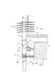
図4と図5と図7と図9に示すように、軸部材2は、複数個の円環状部材1…を相互に軸心所定間隔に保持する複数の凹周溝7…を有している。さらに、詳しく説明すると、軸部材2は、一端2a側と他端2b側に搬送手段4の受け具9,9にて支持される被支持部24,24を有し、かつ、被支持部24,24の間に軸心所定間隔に形成された複数の取付用凹周溝25…を有する軸本体23と、軸本体23の取付用凹周溝25…の各々に外嵌されたリング状の滑止め部材26…を有している。即ち、図6に示す如く、軸本体23の取付用凹周溝25に滑止め部材26を取付けて、滑止め部材26の外周面27と取付用凹周溝25の内側面28,28とで、軸部材2の上記凹周溝7を形成している。なお、滑止め部材26としては、例えばシリコーンゴム製の収縮チューブを輪切りして製作される。
【0016】
また、図4に示すように、軸本体23の一端2a側の被支持部24には、所定間隔で一対の外鍔部29,29が設けられると共に、一端2a側の外鍔部29近傍には、(後述の強制回転手段5の)ピニオンギヤ10が設けられている。
【0017】
しかして、本発明の接着剤塗布装置は、図1と図8と図9に示すように、搬送手段4によって接着剤6の液面6aにまで接近した軸部材2を(矢印Aの如く)回転させて軸部材2に吊持された円環状部材1…を(矢印Bの如く)連れ廻りさせる強制回転手段5を、具備している。
【0018】
即ち、強制回転手段5は、軸部材2の一端2a側に設けられた上記ピニオンギヤ10と、接着剤槽3の接着剤6の液面6aに接近した高さ位置及びその手前位置とその下流側Dの乾燥完了の位置にわたって設けられてピニオンギヤ10と噛合するラック部材11と、を備えている。さらに詳しくは、基台部12の左右側壁12a,12aの内の一方であって、切欠部16の水平面部18に上記ラック部材11が付設されている。
【0019】
また、接着剤槽3の下流側Dには、接着剤6が塗布された円環状部材1に冷風を送る液切用ファン21と、弱温風を送る乾燥用ファン22が設けられている。このように構成された接着剤塗布装置は、接着剤槽3よりも上流側Uを自動搬入手段又は人手(図示省略)によって円環状部材1を供給する円環状部材供給ゾーンとされ、接着剤槽3よりも下流側Dを接着剤乾燥ゾーンとされている。
【0020】
次に、本発明の接着剤塗布装置についての作用を説明する。図1と図2に示すように、接着剤6の塗布作業に於ては、先ず、搬送手段4の左右のチェ−ン8,8を低速───搬送速度としては、例えば100mm/min ───で駆動し、かつ、予め各凹周溝7…に1個ずつ円環状部材1を保持させておいた軸部材2を順次左右の受け具9,9に(自動搬入手段又は人力にて)設置していく。このとき、ラック部材11側にピニオンギヤ10を向けて軸部材2を受け具9,9に設置する。なお、図5に示す如く、軸部材2の凹周溝7に円環状部材1を保持させると、やや傾いた状態となる。
【0021】
図1と図2にもどって、受け具9,9に水平状に支持された各軸部材2…は、水平方向下流側Dへ順次搬送されていくが、円環状部材供給ゾーンから軸部材2…は回転を開始する。即ち、図8と図9に示す如く、ピニオンギヤ10がラック部材11に噛合して軸部材2が(矢印A方向に)回転を開始する。そして、軸部材2が接着剤槽3の位置まで搬送されると、図1と図8に示す如く、軸部材2が基台部12の第1勾配面部17に沿って下降して接着剤6の液面6aへ接近すると共に、軸部材2に吊持された複数個の円環状部材1…の下部が接着剤6内へ浸漬していく。
【0022】
軸部材2が水平面部18に沿ってさらに移動するが、このとき、図10に示す如く、軸部材2の各凹周溝7…に保持された各円環状部材1…が、回転する軸部材2にて連れ廻りされて(矢印B方向に)回転を続ける。即ち、軸部材2に対して各円環状部材1…は滑りを生ずることなく回転し、かつ、水平方向下流側Dへ移動していく。
【0023】
しかして、図11は、回転しつつ移動する円環状部材1に於て、接着剤6内を通って液面6aから上がっていく側の部分(図10のC−C線の拡大断面図)を示している。ところで、円環状部材1はゆっくりとした速度で回転するため、円環状部材1の液面6aから上がっていく側の部分に塗布された余分な接着剤6は、液面6a側に引き寄せられる。従って、接着剤6内にスラッジ等の汚れ30が混じっていても上記余分な接着剤6と一緒に液面6a側に流れ落ち、円環状部材1に汚れ30が付着しない。
【0024】
また、図6と図9に示すように、円環状部材1は傾斜状に軸部材2の凹周溝7に保持されているため、円環状部材1の孔部1aと凹周溝7の外周面27との間には隙間を生じ、円環状部材1と凹周溝7とは面接触しない。従って、円環状部材1の孔部1a内周縁に塗布された接着剤6が凹周溝7の外周面27に付着し難くなり、孔部1a内周縁に接着剤膜が薄くきれいに形成される。また、傾斜状に保持されているため、円環状部材1の凹部1bに接着剤6が溜まることがない。
【0025】
その後、ピニオンギヤ10がラック部材11に噛合したままであって、軸部材2は回転を続けて、各円環状部材1…がゆっくりと回転しながら、図1と図3に示すように、軸部材2は第2勾配面部19に沿って上昇すると共に、各円環状部材1…が接着剤6内から引き上げられる(乾燥が開始される)。そして、第2勾配面部19を通過した軸部材2は再び基台部12の上端縁15に沿って水平方向に移動し、液切用ファン21からの冷風にて各円環状部材1…に付着した余分な接着剤6が液切りされ、乾燥用ファン22からの弱温風にて接着剤6が乾燥して円環状部材1表面に接着剤膜が形成される。このように、接着剤槽3から出た瞬間から(ゆっくりと回転しながら)円環状部材1の接着剤付着部の乾燥が始まり、かつ、円環状部材1と凹周溝7とは面接触しない(図6と図9参照)ので、外周面27に接着剤が付着しない。
【0026】
そして、軸部材2が下流側Dまで搬送されると、(自動排出手段又は手動にて)軸部材2を受け具9,9から取外し、接着剤膜が形成された各円環状部材1…を軸部材2から抜き取って所定の場所に収納する。このように、接着剤膜が形成された円環状部材1…を吊持した軸部材2…が順次下流側Dに搬送される。
【0027】
ところで、図7に示すように、軸部材2の凹周溝7の外径寸法をφ2 とし、円環状部材1の孔部1aの内径寸法をφ1 とすると、軸部材2に対する円環状部材1の回転比はφ2 π/φ1 πとなる。
【0028】
しかして、本発明に於て、上記回転比は、円環状部材1の大きさが大小異なっても一定とされている。つまり、円環状部材1の孔部1aの内径寸法φ1 が大きくなれば、それに比例して軸部材2の凹周溝7の外径寸法φ2 も大きく設定する。なお、軸部材2のピニオンギヤ10の歯数は一定である。
【0029】
このように、円環状部材1の孔部1aの内径寸法φ1 に対応した外径寸法φ2 の凹周溝7を有する軸部材2を作製することによって、搬送速度を一定として軸部材2毎に異なる種類(大きさ)の円環状部材1を吊持して搬送させ、接着剤6を塗布させることができる。換言すると、ピニオンギヤ10がラック部材11に噛合して軸部材2が回転する間に於て、大きい円環状部材1も小さい円環状部材1も、回転する回数(例えば3回)は同じとなり、夫々にほぼ同一の薄い膜圧の接着剤膜を形成することができる。
【0030】
また、図12〜図14は、夫々異なる形状の軸部材2を示している。図12と図13に示す軸部材2は、軸本体23の取付用凹周溝25に(上述と同様の)滑止め部材26が外嵌されたものである。また、図14に示す軸部材2は、滑止め部材が省略されたものであり、軸部材2の凹周溝7にサンドブラストを施して滑止めを行っている。
【0031】
なお、本発明は上述の実施の形態に限定されず、例えば、本実施の形態では、円環状部材1下部を孔部1aまで接着剤6内に浸漬させた場合を例示したが、円環状部材1下部の外周縁近傍が浸漬する程度とする場合もある。また、本発明に於て、「接着剤」とは、溶剤や塗料を含むものと定義する。また、軸部材2は水平状に限らず、(水平に対して)傾斜状としても自由である。また、接着剤槽3は天井壁のある形状として、側壁窓部又は天井窓部から、チェーン8等の搬送手段の一部を搬入搬出移動させるも自由である。
【0032】
【発明の効果】
本発明は上述の如く構成されるので、次に記載する効果を奏する。
【0033】
(請求項1によれば)均一で極薄い接着剤膜を円環状部材1に確実かつ簡単に形成することができる。また、(従来のように)液切りする時間や円環状部材1をどぶ付けしたバスケットの後処理等の時間のロスや、接着剤の無駄が無くなり、効率良く塗布作業を行うことができる。
【0034】
また、円環状部材1を軸部材2にて吊持しつつ回転させて接着剤6を塗布するので、円環状部材1の凹部1bに接着剤6が溜まることが無く、かつ、接着剤6にスラッジ等の汚れ30が混じっていてもその汚れ30が接着剤6の液面6a側へ引き戻されて円環状部材1の表面に付着せず、不良品が大幅に減少する。
【0035】
(請求項2によれば)1個の凹周溝7に1個の円環状部材1を吊持して、1本の軸部材2に複数個の円環状部材1…を吊持しつつ回転させて接着剤6を塗布させることができる。このとき、各円環状部材1…は軸心所定間隔で吊持されるので、(従来のように)各円環状部材1…に塗布された接着剤6部分が相互に当たって接着剤膜が歪に形成されるようなことが無い。さらに、軸部材2毎に種類の異なる円環状部材1を吊持させて小量多品種生産に対応することもできる。
【0036】
(請求項3によれば)搬送手段の構造が簡単であり、作製が容易である。また、軸部材の搬送手段への取付け・取外しが容易かつ迅速に行い得る。
(請求項4によれば)搬送される軸部材2自体を利用して強制回転手段5を簡単な構造とすることができる。
【図面の簡単な説明】
【図1】本発明の実施の一形態を示す簡略構成説明図である。
【図2】下流側から見た簡略構成説明図である。
【図3】基台部を示す説明図である。
【図4】軸部材を示す平面図である。
【図5】軸部材に複数の円環状部材を吊持した状態を示す断面図である。
【図6】円環状部材と軸部材との接触部位を示す拡大断面図である。
【図7】軸部材に円環状部材を吊持した状態を示す断面図である。
【図8】軸部材が回転し始める状態を示す説明図である。
【図9】下流側から見て円環状部材が接着剤内に浸漬した状態を示す説明図である。
【図10】円環状部材が接着剤内に浸漬した状態を示す説明図である。
【図11】円環状部材の接着剤への浸漬状態を示す拡大断面図である。
【図12】他の形状の軸部材を示す要部半截断面図である。
【図13】別の形状の軸部材を示す要部半截断面図である。
【図14】さらに別の形状の軸部材を示す要部半截断面図である。
【符号の説明】
1 円環状部材
1a 孔部
2 軸部材
2a 一端
3 接着剤槽
4 搬送手段
5 強制回転手段
6 接着剤
6a 液面
7 凹周溝
8 チェーン
9 受け具
10 ピニオンギヤ
11 ラック部材
23 軸本体
25 取付用凹周溝
26 滑止め部材
27 外周面
28 内側面 [0001]
BACKGROUND OF THE INVENTION
The present invention relates to an adhesive application device for an annular member.
[0002]
[Prior art]
Conventionally, when an adhesive is applied to an annular member having a hole, the annular member is placed in a basket and the annular member is immersed in the adhesive tank containing the adhesive (so-called “dobbling”). The basket is pulled up to remove excess adhesive from the annular member.
[0003]
[Problems to be solved by the invention]
However, the above method has caused the following problems.
(1) A time loss for draining liquid occurs.
(2) A uniform and extremely thin adhesive film is ideal, but a large amount of adhesive is applied by bumping, resulting in non-uniform adhesive film and an increased film pressure. In addition, there is a lot of waste of the adhesive.
{Circle around (3)} Depending on the shape of the annular member (for example, the shape having a recessed portion), the adhesive is dried while it is accumulated, resulting in a defective product.
(4) When there is dirt such as sludge in the adhesive tank, the dirt adheres to the surface of the annular member, and the adhesive is dried as it is.
(5) The adhesive film is distorted at the contact portions between the annular members or between the annular member and the basket, which causes poor adhesion.
{Circle around (6)} Since the entire basket is immersed in the adhesive tank, post-treatment of the basket (removal of the adhesive) is necessary, which is troublesome.
(7) A large scale is required by a device for raising and lowering the basket.
[0004]
Therefore, an object of the present invention is to provide an adhesive application device that solves the above-described problems, improves work efficiency, and can finish with high quality.
[0005]
[Means for Solving the Problems]
In order to achieve the above-mentioned object, an adhesive application device according to the present invention is an apparatus for applying an adhesive to an annular member having a hole at the center, and is inserted into the hole to form a plurality of the above-mentioned objects. A shaft member having a shaft main body for mutually suspending the annular members at a predetermined axial center , an adhesive tank containing an adhesive, and transporting the shaft member while rotatably supporting the shaft member. Conveying means for bringing the shaft member close to the adhesive liquid level and immersing the lower part of the annular member in the adhesive; and rotating the shaft member approaching the adhesive liquid level by the conveying means. Forcibly rotating means for rotating the annular member suspended by the shaft member, and each of a plurality of mounting concave circumferential grooves formed at predetermined intervals on the shaft main body has a ring-like shape. A non-slip member is externally fitted, and the outer peripheral surface of the non-slip member contacts the annular member. It was configured to equity.
[0006]
Also, a holding concave circumferential groove for holding the annular member is formed by the inner side surface of the mounting concave circumferential groove of the shaft body and the outer circumferential surface of the non-slip member.
Further, the transporting means includes two endless chains arranged in parallel when viewed in plan, and a receiver that is arranged on the chain at a predetermined pitch and removably supports both ends of the shaft member. I have.
[0007]
The forced rotation means includes a pinion gear provided on one end side of the shaft member, and a rack member provided at a height position close to the adhesive liquid surface of the adhesive tank and meshing with the pinion gear. .
[0008]
DETAILED DESCRIPTION OF THE INVENTION
Hereinafter, the present invention will be described in detail with reference to the drawings illustrating embodiments.
[0009]
1 and 2 show an embodiment of an adhesive application device according to the present invention, which is an apparatus for applying an adhesive to an
[0010]
Here, as shown in FIGS. 5 and 7, the
[0011]
Thus, the adhesive application device of the present invention will be described in detail. As shown in FIGS. 1, 2, 8, and 9, the
[0012]
Further, as shown in FIGS. 3 and 9, a
[0013]
Then, the upper side of the
[0014]
As shown in FIGS. 1 to 3, the
[0015]
As shown in FIGS. 4, 5, 7, and 9, the
[0016]
Further, as shown in FIG. 4, the supported
[0017]
Thus, the adhesive application device of the present invention, as shown in FIGS. 1, 8, and 9, moves the
[0018]
That is, the forcible
[0019]
Further, on the downstream side D of the
[0020]
Next, the operation of the adhesive application device of the present invention will be described. As shown in FIG. 1 and FIG. 2, in the application work of the adhesive 6, first, the left and
[0021]
1 and 2, the
[0022]
The
[0023]
Thus, FIG. 11 shows the portion of the
[0024]
Further, as shown in FIGS. 6 and 9, since the
[0025]
Thereafter, the
[0026]
Then, when the
[0027]
By the way, as shown in FIG. 7, when the outer diameter of the
[0028]
Therefore, in the present invention, the rotation ratio is constant even when the size of the
[0029]
Thus, by producing the
[0030]
12 to 14
[0031]
In addition, this invention is not limited to the above-mentioned embodiment, For example, in this embodiment, although the case where the
[0032]
【The invention's effect】
Since this invention is comprised as mentioned above, there exists an effect described below.
[0033]
A uniform and extremely thin adhesive film can be reliably and easily formed on the annular member 1 (according to claim 1). Further, the time for draining (as in the prior art), the time loss of the post-treatment of the basket on which the
[0034]
Further, since the
[0035]
(According to claim 2) One
[0036]
(According to claim 3) The structure of the conveying means is simple and easy to manufacture. Further, the shaft member can be easily and quickly attached to and detached from the conveying means.
According to the fourth aspect, the forced rotation means 5 can have a simple structure by using the
[Brief description of the drawings]
FIG. 1 is an explanatory diagram of a simplified configuration showing an embodiment of the present invention.
FIG. 2 is an explanatory diagram of a simplified configuration viewed from the downstream side.
FIG. 3 is an explanatory view showing a base part.
FIG. 4 is a plan view showing a shaft member.
FIG. 5 is a cross-sectional view showing a state in which a plurality of annular members are suspended from a shaft member.
FIG. 6 is an enlarged cross-sectional view showing a contact portion between an annular member and a shaft member.
FIG. 7 is a cross-sectional view showing a state in which an annular member is suspended from a shaft member.
FIG. 8 is an explanatory view showing a state in which a shaft member starts to rotate.
FIG. 9 is an explanatory view showing a state in which an annular member is immersed in an adhesive as viewed from the downstream side.
FIG. 10 is an explanatory view showing a state in which an annular member is immersed in an adhesive.
FIG. 11 is an enlarged cross-sectional view showing a state in which an annular member is immersed in an adhesive.
FIG. 12 is a cross-sectional view of the main part of a shaft member showing another shape of a shaft member.
FIG. 13 is a cross-sectional view of a main part of a shaft showing another shape of a shaft member.
FIG. 14 is a cross-sectional view of a main part of a shaft showing another shape of the shaft member.
[Explanation of symbols]
DESCRIPTION OF
10 Pinion gear
11 Rack member
23 axis body
25 recessed groove for mounting
26 Non-slip member
27 outer peripheral surface
28 inner surface
Claims (4)
上記軸本体に軸心所定間隔に形成された複数の取付用凹周溝の夫々に、リング状の滑止め部材が外嵌され、該滑止め部材の外周面が、上記円環状部材を接触保持するように構成したことを特徴とする接着剤塗布装置。An apparatus for applying an adhesive to an annular member having a hole in the center, the shaft having a shaft body that is inserted through the hole and suspends the plurality of annular members from each other at a predetermined axial center. A member, an adhesive tank containing an adhesive, and the shaft member being rotatably supported while being conveyed, the shaft member being brought close to the adhesive liquid level of the adhesive tank, and the lower part of the annular member being Conveying means for immersing in the adhesive, and forced rotating means for rotating the shaft member approaching the adhesive liquid level by the conveying means and rotating the annular member suspended by the shaft member and, with a,
A ring-shaped non-slip member is fitted on each of the plurality of mounting concave grooves formed at predetermined intervals on the shaft main body, and the outer peripheral surface of the non-slip member holds the annular member in contact with the shaft main body. An adhesive application device characterized by being configured to do so .
Priority Applications (1)
| Application Number | Priority Date | Filing Date | Title |
|---|---|---|---|
| JP32344598A JP3670497B2 (en) | 1998-11-13 | 1998-11-13 | Adhesive applicator |
Applications Claiming Priority (1)
| Application Number | Priority Date | Filing Date | Title |
|---|---|---|---|
| JP32344598A JP3670497B2 (en) | 1998-11-13 | 1998-11-13 | Adhesive applicator |
Publications (2)
| Publication Number | Publication Date |
|---|---|
| JP2000140733A JP2000140733A (en) | 2000-05-23 |
| JP3670497B2 true JP3670497B2 (en) | 2005-07-13 |
Family
ID=18154755
Family Applications (1)
| Application Number | Title | Priority Date | Filing Date |
|---|---|---|---|
| JP32344598A Expired - Lifetime JP3670497B2 (en) | 1998-11-13 | 1998-11-13 | Adhesive applicator |
Country Status (1)
| Country | Link |
|---|---|
| JP (1) | JP3670497B2 (en) |
Families Citing this family (3)
| Publication number | Priority date | Publication date | Assignee | Title |
|---|---|---|---|---|
| JP6807022B2 (en) * | 2016-12-28 | 2021-01-06 | 日立金属株式会社 | Manufacturing method of resin-coated magnetic core and resin-coated magnetic core |
| JP2021005734A (en) * | 2020-10-12 | 2021-01-14 | 日立金属株式会社 | Magnetic core with resin coating |
| JP7310990B2 (en) | 2020-10-12 | 2023-07-19 | 株式会社プロテリアル | Method for manufacturing magnetic core with resin coating |
-
1998
- 1998-11-13 JP JP32344598A patent/JP3670497B2/en not_active Expired - Lifetime
Also Published As
| Publication number | Publication date |
|---|---|
| JP2000140733A (en) | 2000-05-23 |
Similar Documents
| Publication | Publication Date | Title |
|---|---|---|
| JPS6255906B2 (en) | ||
| JP2020032526A (en) | Apparatus and method for installing pre-molded seal cap | |
| US4385083A (en) | Apparatus and method for forming a thin film of coating material on a substrate having a vacuum applied to the edge thereof | |
| JP3670497B2 (en) | Adhesive applicator | |
| JPH0543428B2 (en) | ||
| CN113292246B (en) | Continuous production device for glass thinning | |
| JP2911406B2 (en) | Surface treatment equipment | |
| JPH08155357A (en) | Conveyor for spray coating | |
| JP2877217B2 (en) | Surface treatment equipment | |
| JPH0889875A (en) | Method and apparatus for coating simultaneously inner surface and outer surface of metal pipe | |
| JPH044844Y2 (en) | ||
| JPH0545408Y2 (en) | ||
| JPH01123656A (en) | Device for coating conduit tube | |
| JPS5855975Y2 (en) | Paint film uniformity device for electrical parts coating equipment | |
| JPS59172320A (en) | Device for supplying lubricant liquid to slat conveyor | |
| KR0159247B1 (en) | Device for coating substrates in semiconductor manufacture | |
| KR830001536B1 (en) | Coating method and device to maintain uniform thickness | |
| KR930003159Y1 (en) | Coating material carrier structure for decoration coating apparatus | |
| JPS5844950Y2 (en) | Conveyance device | |
| JPS6048824A (en) | Parts feeder | |
| JPS63232868A (en) | Continuous coating device | |
| JPS627620Y2 (en) | ||
| JPS6231178Y2 (en) | ||
| JPH046163Y2 (en) | ||
| JPS6212547A (en) | Semiconductor substrate conveying mechanism |
Legal Events
| Date | Code | Title | Description |
|---|---|---|---|
| A977 | Report on retrieval |
Free format text: JAPANESE INTERMEDIATE CODE: A971007 Effective date: 20040616 |
|
| A131 | Notification of reasons for refusal |
Free format text: JAPANESE INTERMEDIATE CODE: A131 Effective date: 20041005 |
|
| A521 | Written amendment |
Free format text: JAPANESE INTERMEDIATE CODE: A523 Effective date: 20041109 |
|
| TRDD | Decision of grant or rejection written | ||
| A01 | Written decision to grant a patent or to grant a registration (utility model) |
Free format text: JAPANESE INTERMEDIATE CODE: A01 Effective date: 20050315 |
|
| A61 | First payment of annual fees (during grant procedure) |
Free format text: JAPANESE INTERMEDIATE CODE: A61 Effective date: 20050414 |
|
| R150 | Certificate of patent or registration of utility model |
Free format text: JAPANESE INTERMEDIATE CODE: R150 |
|
| FPAY | Renewal fee payment (event date is renewal date of database) |
Free format text: PAYMENT UNTIL: 20090422 Year of fee payment: 4 |
|
| FPAY | Renewal fee payment (event date is renewal date of database) |
Free format text: PAYMENT UNTIL: 20100422 Year of fee payment: 5 |
|
| FPAY | Renewal fee payment (event date is renewal date of database) |
Free format text: PAYMENT UNTIL: 20110422 Year of fee payment: 6 |
|
| FPAY | Renewal fee payment (event date is renewal date of database) |
Free format text: PAYMENT UNTIL: 20110422 Year of fee payment: 6 |
|
| FPAY | Renewal fee payment (event date is renewal date of database) |
Free format text: PAYMENT UNTIL: 20120422 Year of fee payment: 7 |
|
| FPAY | Renewal fee payment (event date is renewal date of database) |
Free format text: PAYMENT UNTIL: 20130422 Year of fee payment: 8 |
|
| EXPY | Cancellation because of completion of term |