JP3669902B2 - Cargo handling vehicle - Google Patents
Cargo handling vehicle Download PDFInfo
- Publication number
- JP3669902B2 JP3669902B2 JP2000213627A JP2000213627A JP3669902B2 JP 3669902 B2 JP3669902 B2 JP 3669902B2 JP 2000213627 A JP2000213627 A JP 2000213627A JP 2000213627 A JP2000213627 A JP 2000213627A JP 3669902 B2 JP3669902 B2 JP 3669902B2
- Authority
- JP
- Japan
- Prior art keywords
- distance
- fork
- loading platform
- vehicle body
- cargo handling
- Prior art date
- Legal status (The legal status is an assumption and is not a legal conclusion. Google has not performed a legal analysis and makes no representation as to the accuracy of the status listed.)
- Expired - Fee Related
Links
Images


Description
【0001】
【発明の属する技術分野】
本発明はフォークリフト等の荷役車両に関する。
【0002】
【従来の技術】
荷役車両として一般的なフォークリフトのうちには、図4で示すような構成とされてカウンタバランス型といわれるものがある。そして、このフォークリフトは、荷物が載置される荷台であるフォーク21と、フォーク21の昇降動作を案内する支柱であるマスト22とが前側位置に配設されており、かつ、その後側位置にはカウンタウエイト23が配設された車両本体24を備えている。また、この際、フォーク21を昇降自在に支持したマスト22に沿っては油圧シリンダ25が立設されており、この油圧シリンダ25をアクチュエータとして車両本体24に配設された昇降装置(図示省略)によってフォーク21は昇降動作させられることになっている。
【0003】
さらに、車両本体24には走行モータ26が内装されており、この走行モータ26をアクチュエータとする走行装置(図示省略)によっては車両本体24そのもの、つまり、フォークリフト自体が前後方向に沿って進退動作させられると共に、旋回動作させられることになっている。さらにまた、この車両本体24に配設された運転席パネル27の内部には、マイクロコンピュータを利用して構成されたコントローラ28が設けられており、このコントローラ28によっては、昇降装置や走行装置などのような装置個々の動作や互いの連携した動作などが統括的に制御されている。
【0004】
【発明が解決しようとする課題】
ところで、この種のフォークリフトを使用することによっては、フォーク21を上昇動作させたうえでのラック棚(図示省略)に対する荷積み作業や荷取り作業が実行されることになっており、例えば、荷取り作業にあっては、車両本体24の前進動作に伴ってラック棚内に差し込まれたフォーク21上にパレット積みされた荷物を載置した後、車両本体24の後退動作に伴ってフォーク21をラック棚外にまで後退動作させたうえで下降動作させることが行われる。
【0005】
しかしながら、車両本体24に着座しているオペレータとフォーク21との間には、フォーク21の基端部に取り付けられたリフトブラケット(図示省略)やバックレスト29などが介在しているため、オペレータが目視によってフォーク21の後退動作を確認することは困難である。また、ラック棚は薄暗い倉庫内に設置されているのが通常であるから、フォーク21がラック棚外にまで出切ったことを視認するのもやはり困難であり、誤判断したオペレータがフォーク21を下降動作させたため、フォーク21がラック棚と接触する結果を招いて荷崩れが発生することも起こっていた。
【0006】
本発明はこのような不都合に鑑みて創案されたものであり、下降動作中のフォークがラック棚と接触することを有効に防止し得る構成とされた荷役車両の提供を目的としている。
【0007】
【課題を解決するための手段】
本発明の請求項1に係る荷役車両は、荷物が載置される荷台と、この荷台を支柱に沿って昇降動作させる昇降装置と、荷台及び支柱が前側位置に配設され、かつ、昇降装置が配設された車両本体と、この車両本体に配設されて車両本体そのものを進退動作させる走行装置とを備えていると共に、荷台の上昇動作後に前進動作を開始した車両本体の前進距離を測定し、かつ、前進動作の終了後に後退動作を開始した車両本体の後退距離を測定する移動距離測定手段と、移動距離測定手段の測定動作実行を指示する測定実行指示手段と、後退動作を開始した車両本体の後退距離がその前進距離以上となるまで荷台の下降動作を禁止する動作制御手段とを具備していることを特徴とする。
【0008】
本発明の請求項2に係る荷役車両は、荷台の高さ位置を検出する揚高検出手段を請求項1記載の構成に加えて具備したものであり、動作制御手段は、予め設定された基準位置を超えた高さ位置にある荷台が予め設定された上下許容範囲を超えるまで荷台の上昇動作及び下降動作を許容するものであることを特徴としている。
【0009】
本発明の請求項3に係る荷役車両は請求項1または請求項2に記載したものであり、動作制御手段は、車両本体の後退距離がその前進距離以上となった時点で車両本体の後退動作を停止させるものであることを特徴としている。
【0010】
本発明の請求項4に係る荷役車両は請求項1ないし請求項3のいずれかに記載したものであって、動作制御手段は、車両本体の後退距離がその前進距離以上となった時点で荷台の下降動作を開始させるものであることを特徴としている。
【0011】
本発明の請求項5に係る荷役車両は請求項1ないし請求項4のいずれかに記載したものであり、動作制御手段による下降動作の禁止制御を解除する制御解除手段を具備していることを特徴とする。
【0012】
本発明の請求項6に係る荷役車両は請求項1ないし請求項5のいずれかに記載したものであり、動作制御手段の動作状態を外部に告知する通報手段または警報手段を具備していることを特徴とする。
【0013】
【発明の実施の形態】
以下、本発明の実施の形態を図面に基づいて説明するが、本実施の形態では荷役車両がフォークリフトであるとしている。しかしながら、荷役車両がフォークリフトのみに限定されることはないのであり、荷物が載置される荷台と、この荷台を支柱に沿って昇降動作させる昇降装置と、荷台及び支柱が前側位置に配設され、かつ、昇降装置が配設された車両本体と、この車両本体に配設されて車両本体そのものを進退動作させる走行装置とを備えてなる荷役車両でありさえすればフォークリフト以外であってもよいことは勿論である。
【0014】
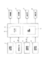
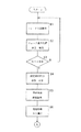
図1は本実施の形態に係るフォークリフトが具備している制御系統の要部を示すブロック図、図2は制御の前段過程を示すフローチャートであり、図3は制御の後段過程を示すフローチャートである。なお、本実施の形態に係るフォークリフトはカウンタバランス型であり、その全体構造は図4で示した従来の形態と基本的に異ならないので、ここでの図示は省略することとし、フォークリフトの全体構造については図4を参照しながら説明する。
【0015】
本実施の形態に係るフォークリフトは、図1及び図4で示すように、パレット積みなどされた荷物が載置される荷台であるフォーク21と、このフォーク21の昇降動作を案内する支柱であるマスト22とが前側位置に配設されており、その後側位置にはカウンタウエイト23が配設された車両本体24を備えている。そして、フォーク21を昇降自在に支持したマスト22に沿っては油圧シリンダ25が立設されており、この油圧シリンダ25をアクチュエータとして車両本体24の内部に配設された昇降装置1、つまり、油圧系の昇降装置1が運転されるのに伴ってフォーク21はマスト22に沿って昇降動作することになっている。
【0016】
なお、このフォーク21が上昇動作を開始したことはマスト22の所定位置に配置されたリミットスイッチなどのような検知センサである上昇開始検知手段2によって検知される一方、上昇動作したフォーク21の高さ位置はリール式ポテンショメータやマグネットセンサなどのような周知の揚高検出手段3を利用することによって検出されている。
【0017】
また、車両本体24の内部には走行モータ26が配設されており、この走行モータ26をアクチュエータとする電気系の走行装置4によっては車両本体24そのもの、つまり、フォークリフト自体が前後方向に沿って進退動作させられ、かつ、旋回動作させられることになる。さらに、この際における車両本体24の前進距離S1及び後退距離S2は、車両本体24の前進距離S1をアップカウントする一方で後退距離S2をダウンカウントするアップダウン式計測器のような移動距離測定手段5によって測定可能となっている。
【0018】
すなわち、本実施の形態においては、運転席パネル27に配置されたスイッチなどである測定実行指示手段6からのON信号、つまり、測定実行指示を示すON信号が入力したことに基づき、移動距離測定手段5は、フォーク21の上昇動作後に前進動作を開始した車両本体24の前進距離S1を測定し、かつ、この際の前進動作の終了後に後退動作を開始した車両本体24の後退距離S2を測定することになっている。なお、ここでの移動距離測定装置5が例えばタイヤ回転数をカウントするようなアップダウン式計測器のみに限定されず、ロータリエンコーダなどを利用して構成されたものであってもよいことは勿論である。
【0019】
さらにまた、運転席パネル27に対しては、昇降装置1などを手動操作する際に使用される各種の操作レバーと共に、液晶表示器やブザーなどのような通報手段7及び警報手段8が配置されており、この運転席パネル27の内部には、マイクロコンピュータを利用して構成されたコントローラ9、つまり、装置個々の動作及び各種装置の互いに連携した動作などを統括的に制御すると共に、フォーク21の下降動作を禁止しながら動作制御を実現するコントローラ9が配設されている。なお、ここでの通報手段7及び警報手段8それぞれは、コントローラ9の動作状態を外部に対して、具体的には、オペレータに対して告知する機能を果たすことになっている。
【0020】
そして、このコントローラ9は、各種のデータを記憶しているROMやRAMからなるメモリ部10と、CPUからなる演算処理部11とから構成されたものであり、メモリ部10には、荷積み作業時や荷取り作業時におけるフォーク21の下降動作を禁止すべき基準となる高さ位置のデータ、つまり、基準位置H1のデータが記憶されている。なお、この際における基準位置H1とは、荷物を積み込もうとするラック棚の高さ位置、あるいはまた、取り出そうとするラック棚の高さ位置を考慮したうえで予め設定されているフォーク21の到達すべき高さ位置のことである。
【0021】
また、本実施の形態に係るフォークリフトでは、基準位置H1を超えた高さ位置H2にあるフォーク21の上昇動作及び下降動作が許容される上下許容範囲h1が予め設定されており、この上下許容範囲h1に関わるデータもメモリ部10に記憶されている。すなわち、フォーク21による荷積み作業や荷取り作業に際しては、多少の高さ範囲にわたってフォーク21を上下動させるのが一般的であり、フォーク21の実際の高さ位置H2が基準位置H1を超えている限りはフォーク21を多少の高さ範囲にわたって上下動させても不都合はない。しかしながら、このフォーク21の上下移動範囲h2があまりにも大き過ぎると、荷取り作業などに支障を来すことも考えられるので、フォーク21の下降動作が許容される上下許容範囲h1を予め設定しておき、この上下許容範囲h1を設定しておくことによってフォーク21の上下移動範囲h2を規制することが行われる。
【0022】
さらに、コントローラ9を構成している演算処理部11は、車両本体24の前進動作がフォーク21の上昇動作後に開始されたか否か、測定実行指示手段6からON信号が出力されているか否かを判断すると共に、測定実行指示手段6からのON信号が入力している状態下で移動距離測定手段5が測定した車両本体24の後退距離S2がその前進距離S1以上となるまではフォーク21の下降動作を禁止する動作制御手段として機能するものである。そして、この演算処理部11は、荷取り作業などの実情を考慮したうえ、基準位置H1を超えた高さ位置H2にあるフォーク21の上下移動範囲h2が予め設定された上下許容範囲h1を超えるまではフォーク21の上昇動作及び下降動作を許容する制御も実行することになっている。
【0023】
そのため、図1で示すように、上昇開始検知手段2、揚高検出手段3、移動距離測定手段5、測定実行指示手段6のそれぞれからコントローラ9に対しては各種の動作信号及び検出信号が入力しており、コントローラ9から昇降装置1、走行装置4、通報手段7、警報手段8の各々に対しては指示信号が出力されることになっている。なお、本実施の形態では、フォーク21の下降動作が許容される上下許容範囲h1に関わるデータがコントローラ9のメモリ部10に記憶されており、上下移動範囲h2が上下許容範囲h1を超えるまではフォーク21の上昇動作及び下降動作を許容する制御が演算処理部11によって実行されるとしているが、上下許容範囲h1に関わるデータがメモリ部10に記憶されておらず、また、演算処理部11でフォーク21の下降動作を許容する制御が実行されない構成であっても本発明の適用範囲に含まれることは勿論である。
【0024】
つぎに、図2及び図3で示したフローチャートに基づき、本実施の形態に係るフォークリフトが実行する荷取り作業時の制御を説明する。なお、ここではフォークリフトによる荷取り作業時の制御のみを説明しているが、荷積み作業時の制御は荷取り作業時と基本的に同じであるから説明を省略する。
【0025】
まず、荷取り作業時のオペレータは、荷取り作業を実行しようとするラック棚の前面近くまで車両本体24を接近させておいた後、リフトレバーを手動操作することによって昇降装置1の運転を開始したうえ、この昇降装置1の運転に伴って油圧シリンダ25を進出動作させる。すると、フォーク21はマスト22に案内されながらの上昇動作を開始することになり(ステップ1)、フォーク21が上昇動作を開始したことは上昇開始検知手段2によって検知され、また、上昇動作しているフォーク21の実際の高さ位置H2は揚高検出手段3によって検出されることになる(ステップ2)。
【0026】
やがて、フォーク21の実際の高さ位置H2が基準位置H1を超えてしまうと(ステップ3)、引き続いてオペレータは手動によって測定実行指示手段6をON操作することになり(ステップ4)、走行装置4によって車両本体24は前進動作させられる(ステップ5)。そして、車両本体24の前進動作に伴ってはパレット積みの荷物が収納されているラック棚内へとフォーク21が差し込まれることになるが、この際にあっては、測定実行指示手段6がON操作済みであり、しかも、フォーク21の上昇動作後に車両本体24が前進動作を開始しているため、移動距離測定手段5によって車両本体24の前進距離S1が測定されることになる(ステップ6)。なお、ステップ3で測定実行指示手段6をON操作する必然性があるわけではなく、測定実行指示手段6のON操作をステップ3よりも前の時点で行ってもよいことは勿論である。
【0027】
さらに、ラック棚内へと差し込まれたフォーク21は上昇動作及び下降動作させられながらパレット積みされた荷物を持ち上げることになり、ラック棚に収納されていた荷物はフォーク21上に載置される(ステップ7)。ところで、このような上昇動作及び下降動作を実行中であるフォーク21の高さ位置H2も揚高検出手段3によって検出されており、上下それぞれの高さ位置H2に基づいて算出されるフォーク21の上下移動範囲h2が予め設定されている上下許容範囲h1を超えない限り、つまり、h2≦h1である限り、コントローラ9の演算処理部11によってフォーク21の上昇動作及び下降動作は許容されている。
【0028】
その後、荷物を載置したフォーク21は、走行装置4を運転して車両本体24を後退動作させるのに伴ってラック棚外へと後退動作させられることになり(ステップ8)、この際にあっては、フォーク21の現実の高さ位置H2が基準位置H1を超えている状態下で車両本体24が後退動作を開始したため、コントローラ9の演算処理部11によってフォーク21の下降動作を禁止する制御が実行される(ステップ9)。そして、車両本体24が前進動作の終了後に後退動作を開始しているので、フォーク21の後退動作に伴っては移動距離測定手段5によって車両本体24の後退距離S2が測定されることになり(ステップ10)、車両本体24の後退距離S2がその前進距離S1以上となるまではフォーク21の下降動作を禁止する制御が演算処理部11によって実行される(ステップ11)。
【0029】
すなわち、フォーク21が後退動作している間、コントローラ9の演算処理部11では、フォーク21の高さ位置H2が基準位置H1を超えている状態下で車両本体24が後退動作を開始したことに基づき、車両本体24の後退距離S2がその前進距離S1以上となったか否かが判断されており(ステップ11)、後退距離S2が前進距離S1以上とならない限り、つまり、S2<S1である限りはフォーク21の下降動作を禁止する制御が実行される(ステップ9)。そして、フォーク21の下降動作は、車両本体24の後退距離S2がその前進距離S1以上(S2≧S1)となるまで継続されることになり、車両本体24の後退距離S2がその前進距離S1以上になったと演算処理部11が判断した時点でフォーク21の下降動作を禁止する制御が解除される(ステップ12)。
【0030】
そこで、この時点以降においては、リフトレバーを手動操作して昇降装置1の運転を再開したうえで油圧シリンダ25を退入動作させながらフォーク21を基準位置H1よりも下側にまで下降動作させることが可能となる。なお、このフォーク21の下降動作に際してリフトレバーを手動操作する必然性があるわけではなく、車両本体24の後退距離S2がその前進距離S1以上となった時点でフォーク21の下降動作を自動的に開始させる機能を動作制御手段である演算処理部11に付与しておいてもよい。
【0031】
ところで、本実施の形態では、車両本体24の後退距離S2がその前進距離S1以上になったとコントローラ9の演算処理部11が判断した時点でフォーク21の下降動作を禁止する動作制御が解除されるとしているが、この判断を下した演算処理部11が、同時に、車両本体24の後退動作を停止させる動作制御を実行する構成であってもよいことは勿論である。なお、ラック棚内に差し込まれたフォーク21の上昇動作及び下降動作がステップ7で全く実行されない場合、また、車両本体24の後退動作がステップ8で全く実行されない場合などにおいては、通常の荷取り作業などでない、あるいは、故障が発生したとも考えられるので、所定時間の経過を待ったうえでフォーク21の下降動作を禁止する制御の実行を打ち切ってしまうのが実用的である。
【0032】
また、ここでの詳しい説明は省略するが、フォーク21の下降動作を禁止する制御が開始された旨やフォーク21が後退動作中である旨の動作状態を、通報手段7及び警報手段8によってオペレータへと適宜に告知する構成を採用してもよく、このような構成を採用している場合にはオペレータの誤判断が生じがたいという利点が確保される。なお、フォークリフトを使用して行われる荷取り作業の全てでフォーク21の下降動作を禁止する動作制御が必要なわけではなく、フォーク21の下降動作を禁止する必要がない場合には、運転席パネル27に配設されたスイッチなどのような制御解除手段(図示省略)を利用したうえでコントローラ9の演算処理部11によるフォーク21の下降動作の禁止制御を解除するような構成を採用してもよいことは勿論である。
【0033】
【発明の効果】
以上説明したように、本発明に係る荷役車両では、荷台の上昇動作後に前進動作を開始し、かつ、前進動作の終了後に後退動作を開始した車両本体の後退距離がその前進距離以上となるまでは荷台の下降動作を禁止する動作制御が実行されている。そのため、荷積み作業時や荷取り作業時におけるフォークがラック棚の外側に出切ってしまうまではフォークの下降動作が禁止されることとなる結果、下降動作を開始したフォークがラック棚と接触することは起こり得ず、荷崩れの発生を確実かつ有効に防止し得るという効果が得られる。
【図面の簡単な説明】
【図1】本実施の形態に係るフォークリフトが具備する制御系統の要部を示すブロック図である。
【図2】制御の前段過程を示すフローチャートである。
【図3】制御の後段過程を示すフローチャートである。
【図4】本実施の形態及び従来の形態に係るフォークリフトの全体構造を示す側面図である。
【符号の説明】
1 昇降装置
2 上昇開始検知手段
3 揚高検出手段
4 走行装置
5 移動距離測定手段
6 測定実行指示手段
7 通報手段
8 警報手段
9 コントローラ
10 メモリ部
11 演算処理部(動作制御手段)
21 フォーク(荷台)
24 車両本体
S1 前進距離
S2 後退距離[0001]
BACKGROUND OF THE INVENTION
The present invention relates to a cargo handling vehicle such as a forklift.
[0002]
[Prior art]
Among general forklifts as a cargo handling vehicle, there is a so-called counter balance type configured as shown in FIG. In this forklift, a
[0003]
Furthermore, the vehicle
[0004]
[Problems to be solved by the invention]
By the way, by using this type of forklift, the loading and unloading operations on the rack shelf (not shown) after the
[0005]
However, a lift bracket (not shown) or a
[0006]
The present invention has been made in view of such inconveniences, and an object of the present invention is to provide a cargo handling vehicle configured to effectively prevent a fork during a lowering operation from coming into contact with a rack shelf.
[0007]
[Means for Solving the Problems]
A cargo handling vehicle according to a first aspect of the present invention includes a loading platform on which a load is placed, a lifting device that moves the loading platform up and down along the column, a loading platform and a column arranged at a front side position, and the lifting device. And a traveling device that is disposed on the vehicle main body and moves the vehicle main body itself back and forth, and measures the forward distance of the vehicle main body that starts the forward movement after the lifting operation of the loading platform. In addition, the moving distance measuring means for measuring the backward distance of the vehicle body that started the backward movement after the completion of the forward movement, the measurement execution instructing means for instructing the execution of the measurement operation of the moving distance measuring means, and the backward movement started. And an operation control means for prohibiting the lowering operation of the loading platform until the backward distance of the vehicle body becomes equal to or longer than the forward distance.
[0008]
The cargo handling vehicle according to
[0009]
The cargo handling vehicle according to a third aspect of the present invention is the cargo handling vehicle according to the first or second aspect, wherein the operation control means performs the backward movement operation of the vehicle main body when the backward distance of the vehicle main body becomes equal to or greater than the forward distance. It is characterized by the fact that it stops.
[0010]
A cargo handling vehicle according to a fourth aspect of the present invention is the cargo handling vehicle according to any one of the first to third aspects, wherein the operation control means is configured such that when the backward distance of the vehicle body becomes equal to or greater than the forward distance, It is characterized in that the lowering operation of the is started.
[0011]
A cargo handling vehicle according to a fifth aspect of the present invention is the cargo handling vehicle according to any one of the first to fourth aspects, further comprising control release means for releasing the prohibition control of the descending operation by the operation control means. Features.
[0012]
A cargo handling vehicle according to a sixth aspect of the present invention is the cargo handling vehicle according to any one of the first to fifth aspects, and includes a reporting means or a warning means for notifying the operating state of the motion control means to the outside. It is characterized by.
[0013]
DETAILED DESCRIPTION OF THE INVENTION
Hereinafter, embodiments of the present invention will be described with reference to the drawings. In this embodiment, the cargo handling vehicle is a forklift. However, the cargo handling vehicle is not limited to a forklift, and a loading platform on which a load is placed, a lifting device that moves the loading platform up and down along the column, a loading platform and a column are disposed at the front side position. In addition, the vehicle may be other than a forklift as long as it is a cargo handling vehicle including a vehicle main body in which an elevating device is disposed and a traveling device that is disposed in the vehicle main body and moves the vehicle main body back and forth. Of course.
[0014]
FIG. 1 is a block diagram showing a main part of a control system provided in the forklift according to the present embodiment, FIG. 2 is a flowchart showing a pre-control process, and FIG. 3 is a flowchart showing a post-control process. . Note that the forklift according to the present embodiment is a counter balance type, and the overall structure thereof is basically not different from the conventional form shown in FIG. Will be described with reference to FIG.
[0015]
As shown in FIGS. 1 and 4, the forklift according to the present embodiment includes a
[0016]
It is to be noted that the start of the
[0017]
In addition, a traveling
[0018]
That is, in the present embodiment, based on the input of an ON signal from the measurement execution instruction means 6 such as a switch arranged on the driver's
[0019]
Further, the driver's
[0020]
The
[0021]
In the forklift according to the present embodiment, a vertical allowable range h1 in which the ascending and descending operations of the
[0022]
Further, the
[0023]
Therefore, as shown in FIG. 1, various operation signals and detection signals are input to the
[0024]
Next, based on the flowcharts shown in FIG. 2 and FIG. 3, the control at the time of the loading operation performed by the forklift according to the present embodiment will be described. Although only the control during the loading operation by the forklift is described here, the control during the loading operation is basically the same as that during the loading operation, and the description thereof will be omitted.
[0025]
First, the operator at the time of loading operation starts the operation of the
[0026]
Eventually, when the actual height position H2 of the
[0027]
Furthermore, the
[0028]
After that, the
[0029]
That is, while the
[0030]
Accordingly, after this point, the
[0031]
By the way, in the present embodiment, the operation control for prohibiting the lowering operation of the
[0032]
Although detailed explanation is omitted here, the reporting means 7 and the warning means 8 inform the operator that the control state for prohibiting the lowering operation of the
[0033]
【The invention's effect】
As described above, in the cargo handling vehicle according to the present invention, the forward movement is started after the lifting operation of the loading platform, and the backward movement distance of the vehicle main body that has started the backward movement after the completion of the forward movement is equal to or greater than the forward movement distance. The operation control for prohibiting the lowering operation of the cargo bed is executed. As a result, the fork descending operation is prohibited until the fork at the time of loading and unloading work is completely out of the rack shelf. As a result, the fork that has started descending comes into contact with the rack shelf. This is not possible, and the effect of reliably and effectively preventing the occurrence of cargo collapse is obtained.
[Brief description of the drawings]
FIG. 1 is a block diagram showing a main part of a control system provided in a forklift according to an embodiment.
FIG. 2 is a flowchart showing a pre-process of control.
FIG. 3 is a flowchart showing a subsequent process of control.
FIG. 4 is a side view showing the overall structure of a forklift according to the present embodiment and a conventional embodiment.
[Explanation of symbols]
DESCRIPTION OF
21 Fork
24 Vehicle body S1 Forward distance S2 Reverse distance
Claims (6)
Priority Applications (5)
| Application Number | Priority Date | Filing Date | Title |
|---|---|---|---|
| JP2000213627A JP3669902B2 (en) | 2000-07-14 | 2000-07-14 | Cargo handling vehicle |
| GB0114435A GB2366784B (en) | 2000-06-14 | 2001-06-14 | Cargo handling vehicle |
| US09/879,995 US20030024132A1 (en) | 2000-06-14 | 2001-06-14 | Cargo handling vehicle |
| FR0107810A FR2810307B1 (en) | 2000-06-14 | 2001-06-14 | HANDLING VEHICLE, RETRACTABLE TROLLEY AND FORKLIFT |
| DE10128905A DE10128905A1 (en) | 2000-06-14 | 2001-06-15 | Frachtverladunsgfahrzeug |
Applications Claiming Priority (1)
| Application Number | Priority Date | Filing Date | Title |
|---|---|---|---|
| JP2000213627A JP3669902B2 (en) | 2000-07-14 | 2000-07-14 | Cargo handling vehicle |
Publications (2)
| Publication Number | Publication Date |
|---|---|
| JP2002029692A JP2002029692A (en) | 2002-01-29 |
| JP3669902B2 true JP3669902B2 (en) | 2005-07-13 |
Family
ID=18709346
Family Applications (1)
| Application Number | Title | Priority Date | Filing Date |
|---|---|---|---|
| JP2000213627A Expired - Fee Related JP3669902B2 (en) | 2000-06-14 | 2000-07-14 | Cargo handling vehicle |
Country Status (1)
| Country | Link |
|---|---|
| JP (1) | JP3669902B2 (en) |
-
2000
- 2000-07-14 JP JP2000213627A patent/JP3669902B2/en not_active Expired - Fee Related
Also Published As
| Publication number | Publication date |
|---|---|
| JP2002029692A (en) | 2002-01-29 |
Similar Documents
| Publication | Publication Date | Title |
|---|---|---|
| EP2269942B1 (en) | Display device for cargo-handling vehicles | |
| US20030024132A1 (en) | Cargo handling vehicle | |
| GB2385312A (en) | Forklift with pallet clamp | |
| JP3669902B2 (en) | Cargo handling vehicle | |
| JP3669901B2 (en) | Cargo handling vehicle | |
| JP3589951B2 (en) | Reach type forklift | |
| JP4647269B2 (en) | forklift | |
| JP3578332B2 (en) | Cargo handling vehicle | |
| JP2002020093A (en) | Load lifter | |
| JP3578330B2 (en) | Cargo handling vehicle | |
| JP2002029693A (en) | Cargo handling vehicle | |
| JP2002029695A (en) | Cargo handling vehicle | |
| JP3578331B2 (en) | Cargo handling vehicle | |
| JP5489314B1 (en) | Falling prevention device for picking lift and picking lift provided with the fall prevention device | |
| JP2001226095A (en) | Control device for forklift | |
| JP3627978B2 (en) | Cargo handling vehicle | |
| JP2003267691A (en) | Forklift truck | |
| JP5900987B2 (en) | Cargo handling vehicle | |
| EP4292901A1 (en) | Methods for material handling vehicle | |
| JP2006225091A (en) | Fork lift | |
| JP2006298638A (en) | Fork lift | |
| JP4767506B2 (en) | Forklift fork control device | |
| JP3957269B2 (en) | Cargo handling vehicle | |
| JP5999737B2 (en) | Cargo handling vehicle | |
| JP2002068689A (en) | Picking forklift |
Legal Events
| Date | Code | Title | Description |
|---|---|---|---|
| A977 | Report on retrieval |
Free format text: JAPANESE INTERMEDIATE CODE: A971007 Effective date: 20040402 |
|
| A131 | Notification of reasons for refusal |
Free format text: JAPANESE INTERMEDIATE CODE: A131 Effective date: 20040422 |
|
| A02 | Decision of refusal |
Free format text: JAPANESE INTERMEDIATE CODE: A02 Effective date: 20041202 |
|
| A521 | Written amendment |
Free format text: JAPANESE INTERMEDIATE CODE: A523 Effective date: 20041213 |
|
| A911 | Transfer of reconsideration by examiner before appeal (zenchi) |
Free format text: JAPANESE INTERMEDIATE CODE: A911 Effective date: 20050107 |
|
| TRDD | Decision of grant or rejection written | ||
| A01 | Written decision to grant a patent or to grant a registration (utility model) |
Free format text: JAPANESE INTERMEDIATE CODE: A01 Effective date: 20050328 |
|
| A61 | First payment of annual fees (during grant procedure) |
Free format text: JAPANESE INTERMEDIATE CODE: A61 Effective date: 20050412 |
|
| R150 | Certificate of patent or registration of utility model |
Ref document number: 3669902 Country of ref document: JP Free format text: JAPANESE INTERMEDIATE CODE: R150 Free format text: JAPANESE INTERMEDIATE CODE: R150 |
|
| FPAY | Renewal fee payment (event date is renewal date of database) |
Free format text: PAYMENT UNTIL: 20080422 Year of fee payment: 3 |
|
| FPAY | Renewal fee payment (event date is renewal date of database) |
Free format text: PAYMENT UNTIL: 20090422 Year of fee payment: 4 |
|
| R250 | Receipt of annual fees |
Free format text: JAPANESE INTERMEDIATE CODE: R250 |
|
| FPAY | Renewal fee payment (event date is renewal date of database) |
Free format text: PAYMENT UNTIL: 20100422 Year of fee payment: 5 |
|
| R250 | Receipt of annual fees |
Free format text: JAPANESE INTERMEDIATE CODE: R250 |
|
| FPAY | Renewal fee payment (event date is renewal date of database) |
Free format text: PAYMENT UNTIL: 20100422 Year of fee payment: 5 |
|
| FPAY | Renewal fee payment (event date is renewal date of database) |
Free format text: PAYMENT UNTIL: 20110422 Year of fee payment: 6 |
|
| R250 | Receipt of annual fees |
Free format text: JAPANESE INTERMEDIATE CODE: R250 |
|
| FPAY | Renewal fee payment (event date is renewal date of database) |
Free format text: PAYMENT UNTIL: 20110422 Year of fee payment: 6 |
|
| FPAY | Renewal fee payment (event date is renewal date of database) |
Free format text: PAYMENT UNTIL: 20120422 Year of fee payment: 7 |
|
| R250 | Receipt of annual fees |
Free format text: JAPANESE INTERMEDIATE CODE: R250 |
|
| FPAY | Renewal fee payment (event date is renewal date of database) |
Free format text: PAYMENT UNTIL: 20130422 Year of fee payment: 8 |
|
| R250 | Receipt of annual fees |
Free format text: JAPANESE INTERMEDIATE CODE: R250 |
|
| FPAY | Renewal fee payment (event date is renewal date of database) |
Free format text: PAYMENT UNTIL: 20130422 Year of fee payment: 8 |
|
| FPAY | Renewal fee payment (event date is renewal date of database) |
Free format text: PAYMENT UNTIL: 20140422 Year of fee payment: 9 |
|
| R250 | Receipt of annual fees |
Free format text: JAPANESE INTERMEDIATE CODE: R250 |
|
| S533 | Written request for registration of change of name |
Free format text: JAPANESE INTERMEDIATE CODE: R313533 |
|
| R350 | Written notification of registration of transfer |
Free format text: JAPANESE INTERMEDIATE CODE: R350 |
|
| S533 | Written request for registration of change of name |
Free format text: JAPANESE INTERMEDIATE CODE: R313533 |
|
| R350 | Written notification of registration of transfer |
Free format text: JAPANESE INTERMEDIATE CODE: R350 |
|
| LAPS | Cancellation because of no payment of annual fees |