JP3669552B2 - Blender - Google Patents
Blender Download PDFInfo
- Publication number
- JP3669552B2 JP3669552B2 JP28606598A JP28606598A JP3669552B2 JP 3669552 B2 JP3669552 B2 JP 3669552B2 JP 28606598 A JP28606598 A JP 28606598A JP 28606598 A JP28606598 A JP 28606598A JP 3669552 B2 JP3669552 B2 JP 3669552B2
- Authority
- JP
- Japan
- Prior art keywords
- flow direction
- rotating shaft
- direction changing
- container
- mixture
- Prior art date
- Legal status (The legal status is an assumption and is not a legal conclusion. Google has not performed a legal analysis and makes no representation as to the accuracy of the status listed.)
- Expired - Fee Related
Links
Images


Landscapes
- Crushing And Pulverization Processes (AREA)
- Mixers Of The Rotary Stirring Type (AREA)
Description
【0001】
【発明の属する技術分野】
本発明は混合機に関する。
【0002】
【従来の技術】
実公平5−36493号公報は、容器内で軸中心に回転可能に設けられる回転シャフトと、その回転シャフトと同行回転するように設けられる撹拌部材と、その容器の容器内周部に回転可能に設けられる粉砕部材とを備え、その撹拌部材は被混合物を回転シャフトの外周部に向かって流動させる撹拌面を有し、被混合物が容器の容器内周部に付着するのを防止するためのエアー噴出ノズルを備える混合機を開示する。特公平8−15538号公報は、容器内で軸中心に回転可能に設けられる回転シャフトと、その回転シャフトと同行回転するように設けられる撹拌部材と、その容器の容器内周部に回転可能に設けられる粉砕部材とを備え、その撹拌部材は被混合物を回転シャフトの外周部に向かって流動させる撹拌部を有し、その粉砕部材は、同心状に相対回転するせん断リングから構成される混合機を開示する。
【0003】
【発明が解決しようとする課題】
これらの方法によれば、粉砕部材は凝集した被混合物を砕いたり微細化することができるが、粉砕部材は容器内周部に設けられており被混合物は回転シャフトの外周部に向かって流動する(被混合物は粉砕部材から離れる方向に流動する)ので被混合物の粉砕効率が低く、その結果として混合効率が低かった。
従って、本発明の課題はシンプルな構造で回転シャフトの動力負荷の増大を抑え、混合性能を低下させることなく、被混合物の粉砕効率を向上できる混合機を提供することにある。
【0004】
【課題を解決するための手段】
本発明は、被混合物を入れる容器と、容器内で軸中心に回転可能な回転シャフトと、回転シャフトと同行回転可能な撹拌部材及び流動方向変更部材と、回転シャフト外周部に対向する容器内周部で回転可能な粉砕部材とを備え、撹拌部材と流動方向変更部材とが回転シャフト外周部に対して回転径方向に容器内周部から間隔をおいて配置(但し、流動方向変更部材は撹拌部材と回転シャフトとの間に配置)され、且つ撹拌部材が被混合物を回転シャフト外周部に向かって流動させる撹拌面を有し、流動方向変更部材が1枚の曲面状の板状部材で形成され、回転シャフトの軸方向の粉砕部材側において、被混合物の流動方向を流動方向変更部材から容器内周部へ変更させる流動方向変更面を有する混合機を提供する。
【0005】
【発明の実施の形態】
図1、図2に示す横型混合機1は、被混合物を入れる容器2を備える。その容器2は、横軸心の円筒形容器本体2aと、被混合物の投入部2bと、被混合物の排出部2cと、排気部2dとを有する。
その容器2内で、その容器本体2aの軸と同心の横軸中心に回転可能に回転シャフト3が両端支持される。その回転シャフト3は、モータ等の駆動源(図示省略)により、図1において矢印100方向に回転される。
その回転シャフト3と矢印100方向に同行回転するように例えば6つの攪拌部材4が設けられる。本実施形態では、それら攪拌部材4は、回転シャフト3の軸方向において互いに離れた6位置において、回転方向において例えば60度毎に配置されている。なお、図1、図2では回転シャフト3の中央側の2つのみ表示し、回転シャフト3の両端側の4つの図示は省略している。その回転シャフト3の中央側の2つの攪拌部材4は回転方向において例えば180度離れて配置され、他の攪拌部材4も同様に配置される。各攪拌部材4は、容器本体2aの内周部(以下容器内周部2a’という)と非接触状にその近傍に位置するように、その回転シャフト3から突出するアーム5に取り付けられる。
【0006】
図3、図4に示すように、各攪拌部材4は、その回転方向においてアーム5の前方に位置する板状の前壁4aと、その回転シャフト3の軸方向においてアーム5の両側に位置する一対の板状の側壁4b、4cと、その回転シャフト3の径方向において側壁4b、4cの外方に位置する板状の底壁4dとを有する。
撹拌部材4の前壁4aの表面4a’と回転シャフト3の外周部(以下回転シャフト外周部3’という)との距離は、回転方向前方に向かうに従い大きくされており、側壁4bの表面4b’と回転シャフト3の外周部との距離は、回転方向前方に向かうに従い大きくされると共に回転シャフト3の一端に向かうに従い大きくされている。他方の側壁4cは側壁4bと対称形とされている。回転シャフト3の軸方向と径方向における各側壁4b、4cの寸法は、回転方向後方に向かうに従い大きくされている。
【0007】
このように設計することにより前壁4aの表面4a’と側壁4bの表面4b’、側壁4cの表面4c’が、回転シャフト3の回転により被混合物を回転シャフト外周部3’に向かって流動させる撹拌面を構成する。
図2、図3に示すように、各側壁4b、4cの外端縁に、回転時の負荷軽減のために複数の爪4eが好ましくは形成される。なお、爪4eは省略してもよい。その底壁4dの表面4d’は、容器内周部2a’に対して回転径方向(回転シャフト3の径方向)に容器内周部2a’から間隔をおいて配置され、その回転径方向の間隔が一定となるように、その容器内周部2a’、底壁4dの表面4d’及び後述の流動方向変更面7d’は、その回転シャフト3の軸心を中心とする回転体(本実施形態では円柱)に沿う曲面とされていることが好ましい。
【0008】
その容器内周部2a’に例えば6つの粉砕部材6が設けられている。各粉砕部材6は、容器本体2aの回転径方向に沿う軸中心に回転可能な回転シャフト6aと、この回転シャフト6aから回転径方向(回転シャフト6aの径方向)外方に突出する複数のブレード6bとを有し、モータ等の駆動源(図示省略)により回転される。
図1、図2に示すように、本実施形態では、その粉砕部材6は、回転シャフト3の軸方向に離れた3位置に、2つずつ回転シャフト3の回転方向に離れて配置される。
【0009】
即ち、図2、図4に示すように回転シャフト3の軸方向における中央に配置された2つの粉砕部材6の回転軸は回転シャフト3の中央側の2つの撹拌部材4の一方(例えば図2の左側)の撹拌面4b’よりも回転シャフト3の一端側(例えば図2の右端側)に配置され、その撹拌部材4の他方(例えば図2の右側)の撹拌面4c’よりも回転シャフト3の他端側(例えば図2の右端側)に配置される。
回転シャフト3の両端側に配置された4つの粉砕部材6の回転軸と撹拌部材4との位置関係は、回転シャフト3の軸方向における中央に配置されたそれらの関係と同じように配置される。
3つの粉砕部材6の配置高さは、容器本体2aの略1/2の高さとされ、残りの3つの粉砕部材6の配置高さは、容器本体2aの1/2の高さと底部との間とされている。
尚、粉砕部材6は、回転シャフト3の軸方向に離れた3位置に1つずつ配置してもよい。
【0010】
図1、2に示すように、本混合機には、その回転シャフト3と同行回転するように例えば6つの流動方向変更部材7を設けられる。本実施形態では、各流動方向変更部材7は、例えば曲面状部材で形成され、上記各攪拌部材4に一対一で対応し、その回転シャフト3の軸方向の粉砕部材6側で且つ、回転シャフト3の回転径方向で各攪拌部材4と回転シャフト3との間に配置され、上記アーム5に取り付けられる。また、流動方向変更部材7は、攪拌部材4で流動される被混合物の流動方向を流動方向変更部材7から容器内周部2a’へ変更させる機能がある流動方向変更面7d’を有する。この流動方向変更面7d’は図1の一点鎖線300で示すように、被混合物の流動方向を変更する。
流動方向変更部材7dは回転シャフト3の軸方向の粉砕部材6側に設置されているため、被混合物を流動方向変更部材7から容器内周部2a’へ変更(被混合物を粉砕部材6へ集約)する目的以外には被混合物の流動方向が変更されず、混合性能の低下を起こすことなく、回転シャフト3の動力負荷の増大を抑制し、被混合物の粉砕効率を向上できる。
【0011】
流動方向変更部材7は、板状部材で形成するのが好ましい。また、流動方向変更面7d’は、容器内周部2a’に向かって凸曲面部分及び/又は平面部分を有する形状とすることが好ましい。そして、流動方向変更部材7dの流動方向変更面7d’の少なくとも一部が、流動方向変更面7d’の回転軌跡の曲率の0.8〜1.2倍の曲率の曲率部分を有する形状とすることが、回転シャフト3の動力負荷の増大抑制のため、さらに好ましい。こうすれば、流動方向変更部材7d自体の回転抵抗が軽減されるばかりでなく、撹拌部材4により流動される被混合物を略垂直に流動方向変更面7d’で受け(被混合物が流動方向変更部材7dの回転抵抗になる方向で流動方向変更面7d’に当たり難い)、被混合物の流動方向を変更できるため、流動方向変更部材7dを設けたことによる、混合時の回転シャフト3の動力負荷の増大をさらに抑制できる。
【0012】
また、その流動方向変更面7d’は、上記撹拌面4a’、4b’と回転径方向の間隔をおいて対向する部分を有することが好ましい。本実施形態では、回転径方向における流動方向変更面7d’の寸法は回転方向における撹拌部材4の寸法と略等しくされ、回転シャフト3の軸方向における撹拌部材の寸法よりも大きくされることで、回転径方向において流動方向変更面7d’は、撹拌面4a’の略半分及び/又は4b’の全体を覆う。
流動方向変更面7d’の回転方向の前端位置は、撹拌部材4のそれと一致させるか、撹拌部材4の回転方向の前端位置よりも回転方向の後方に配置するのが好ましい。流動方向変更面7d’の回転方向の後端位置は、撹拌部材4と一致させるか撹拌部材4の回転方向の後端位置よりも回転方向の後方に配置するのが好ましい。
【0013】
また、その流動方向変更面7d’は、回転方向後方に向かうに従い回転シャフト3の軸方向における寸法が大きくされている部分を有することにより、回転シャフト外周部3’に向かうに従い回転シャフト3の一端に向かうように流動する被混合物に効率良く接触し、その流動方向を変更できるため、好ましい。
その流動方向変更面7d’は、回転途中で上記粉砕部材部材6の少なくとも一部(本実施形態では全体)と回転径方向において対向する部分を有することが好ましい。これにより、被混合物と粉砕部材6との接触機会をさらに増大し、粉砕部材6による被混合物の粉砕効率を向上できる。
流動方向変更面7d’を上述のように設計することによって、シンプルな構造で、撹拌部材4及び流動方向変更部材7にかかる撹拌抵抗の総和、即ち回転シャフト3の動力負荷の増大を抑え、混合性能を低下させることなく、粉砕効率を向上させることができる。
【0014】
また、図2に示すように、その回転シャフト3と同行回転するように2つの補助攪拌部材10を、回転シャフト3の両端近傍の2位置に設けてもよい。
図1、図2に示すように、その容器本体2aの内部に、被混合物の湿分、温度、組成等の物性調整に用いられる気体を噴出するため、3本のパイプ21を設けてもよい。その際、例えば被混合物の湿分調整のための乾燥した空気や不活性気体、被混合物の温度調整のための温度調節された空気や不活性気体、被混合物と反応して組成調整をするための反応気体等を噴出させるのが好ましい。
【0015】
それらガス供給用パイプ21は、本実施形態では、回転シャフト3の軸方向に離れた例えば3位置に設けられてもよい。例えば、各パイプ21は、容器本体2a内に挿入され、溶接等の公知の固定方法にて容器本体2aに対して一定位置に配される。各パイプ21の先端開口により構成される気体噴出口21aは、混合中の被混合物の中から気体を噴出できるように容器本体2aに対して一定位置に配置される。その容器本体2aに収納される被混合物の体積は、容器本体2aの容積よりも少なくされる。図1における二点鎖線200は、混合中における被混合物の分布領域の一例を示す。
【0016】
各気体噴出口21aから噴出される気体は、上記攪拌部材4の回転方向の前方側に向かうものとされる。さらに、各気体噴出口21aは、噴出気体が容器本体2aの下部から容器本体2aの容器内周部2a’に沿って上方に向かって流動するように、容器本体2aの底部近傍に配置されてもよい。このことにより、 被混合物の分布領域の内部での気体の滞留時間を長くし、被混合物の乾燥や冷却等により、粘着性等の物性調整を効率良く行うことができる。また、その噴出気体が容器本体2aの下部から容器の容器内周部に沿って上方に向かって流動するように、その気体噴出口21aを配置することにより、その容器本体2aに収納される被混合物の体積が容器本体2aに容積よりも大幅に少なくても、被混合物内における気体の滞留時間を可及的に長くし、気体と被混合物との接触効率を向上できる。
【0017】
尚、ガス供給用パイプ21を設ける場合、各パイプ21の先端面21bは、下方に向かうに従い撹拌部材4の回転方向の後方側に向かうように、水平面に対して傾斜させるのが好ましい。そして、そのパイプの先端面21bと水平面とがなす角度θを、粉体状被混合物の安息角以下とするのがさらに好ましい。このことにより、 被混合物がそのパイプ21内部に入り込むのを防止できる。
また、各気体噴出口21aの回転シャフト3の軸方向における位置と上記各粉砕部材6の回転シャフト3の軸方向における位置とは互いに一致するようにしてもよい。即ち、回転シャフト3の軸方向各位置において気体噴出口21aに対して、2つの粉砕部材6は、攪拌転動中の被混合物の中において攪拌部材4の回転方向の前方側に配置してもよい。
【0018】
さらに、図1、2に示されるように、容器本体2aの内部に液体を供給するための3本の液体供給用パイプ31を設けてもよい。その際その液体として、例えば、粉末状の被混合物を粒状にするための造粒液や、被混合物と接触することで化学反応を生じる反応液等を供給するのが好ましい。
それら液体供給用パイプ31は、本実施形態では、回転シャフト3の軸方向に離れた例えば3位置に配置される。 本実施形態では、各パイプ31の先端開口により構成される液体吐出口は、撹拌転動中の被混合物の中から液体を下向きに吐出できるように容器本体2aに対して一定位置に配置される。各液体供給用パイプ31から下向きに吐出される液体は、本実施形態では、上記撹拌部材4の回転方向の後方側に向かうものとされる。 また、パイプ31は同位置に複数配置してもよい。
【0019】
それら液体供給用パイプ31の液体吐出口の回転シャフト3の軸方向における位置と上記粉砕部材6の回転シャフト3の軸方向における位置とは互いに一致するようにしてもよい。 即ち、回転シャフト3の軸方向各位置において液体吐出口に容器本体2aの略1/2の高さに配置された粉砕部材6が対向する。これにより、その容器本体2aの略1/2の高さに配置された各粉砕部材6は、 各パイプ31から供給される液体を分散する分散部材を兼用する。その粉砕部材6の回転シャフト3の軸方向における位置と上記気体噴出口21aの回転シャフト3の軸方向における位置とは互いに一致するようにしてもよい。また、各気体噴出口21aの回転シャフト3の軸方向における位置と上記各粉砕部材6の回転シャフト3の軸方向における位置とは互いに一致させるようにすることが好ましい。これにより、各攪拌部材4は、粉砕部材6と干渉しないように、粉砕部材6が配置されている位置を含む容器本体2aの円周方向領域を通過しない。そのため、各気体噴出口21aの回転シャフト3の軸方向における位置と上記各粉砕部材6の回転シャフト3の軸方向における位置とが互いに一致され、各気体噴出口21aから噴出された気体により、各攪拌部材4が通過しない領域で被混合物が滞留するのが防止され、被混合物が粉砕部材6に向けて流動され、被混合物の粉砕効率が向上される。さらに、液体供給用パイプ31から液体が集中的に供給される部位に気体を流動させることで、その液体供給部位における気体と被混合物との接触効率を向上できる。これにより、その気体による被混合物の乾燥や冷却等により、粘着性等の物性調整を効率良く行うことができる。
【0020】
なお、本発明は上記実施形態に限定されない。
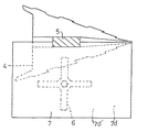
例えば、図5の第1変形例に示すように、流動方向変更面7d’は、回転途中で粉砕部材6の一部とのみ回転径方向において対向する部分を有するものでもよい。
また、流動方向変更面7d’の回転シャフト3の軸方向における寸法は、図5の第1変形例に示すように全体が回転方向後方に向かうに従い大きくされてもよいし、図6の第2変形例に示すように回転方向全域において一定とされてもよい。
また、図7の第3変形例に示すように、粉砕、分散効率を更に向上するため、粉砕部材を増設し、両側に粉砕部材が配置された撹拌部材を存在させた場合には、粉砕部材側に流動方向変更面7d’を配置した結果両側に流動方向変更部材を設置してもよい。
【0021】
また、流動方向変更部材7は、アーム5に直接取り付けなくてもよい。
また、流動方向変更面7d’は、回転シャフト3の径方向において撹拌面4b’と重なる位置に配置する必要はなく、撹拌面4a’、4b’、4c’により撹拌されることで回転シャフト3の外周部に向かって流動する被混合物が存在する粉砕部材6側に配置されていればよい。
上記実施形態では本発明を横型混合機1に適用したが、回転シャフトが縦軸中心に回転する竪型混合機にも本発明を適用できる。
【0022】
【発明の効果】
本発明によれば、シンプルな構造で回転シャフトの動力負荷の増大を抑え、混合性能を低下させることなく、被混合物の粉砕効率を向上できる混合機を提供できる。
【図面の簡単な説明】
【図1】 本発明の実施形態の混合機の側断面図。
【図2】 本発明の実施形態の混合機の部分破断正面図。
【図3】 本発明の実施形態の混合機の要部の斜視図。
【図4】 本発明の実施形態の混合機の要部の正面図。
【図5】 本発明の第1変形例の混合機の部分平面図。
【図6】 本発明の第2変形例の混合機の部分平面図。
【図7】 本発明の第3変形例の混合機の要部の正面図。
【符号の説明】
1;横型混合機
2;容器
2a’;容器内周部
3;回転シャフト
3’;回転シャフト外周部
4;攪拌部材
4a’4b’4c’;撹拌面
6;粉砕部材
7;流動方向変更部材
7d’;流動方向変更面
21;気体噴出パイプ
31;液体供給用パイプ[0001]
BACKGROUND OF THE INVENTION
The present invention relates to a mixer.
[0002]
[Prior art]
In Japanese Utility Model Publication No. 5-36493, a rotating shaft provided rotatably around the axis in a container, a stirring member provided so as to rotate along with the rotating shaft, and a container inner periphery of the container are rotatable. And a stirring member that has a stirring surface that allows the mixture to flow toward the outer peripheral portion of the rotating shaft, and that prevents the mixture from adhering to the inner peripheral portion of the container. Disclosed is a mixer comprising a jet nozzle. Japanese Patent Publication No. 8-15538 discloses a rotating shaft that is provided to be rotatable about an axis in a container, a stirring member that is provided so as to rotate along with the rotating shaft, and a container inner peripheral portion of the container that is rotatable. A mixer comprising: a crushing member provided; the agitation member having an agitation unit that causes the mixture to flow toward the outer peripheral portion of the rotating shaft; and the crushing member includes a concentric relative rotating shear ring Is disclosed.
[0003]
[Problems to be solved by the invention]
According to these methods, the pulverizing member can crush or refine the agglomerated mixture, but the pulverization member is provided on the inner periphery of the container, and the mixture flows toward the outer periphery of the rotating shaft. (The mixed material flows in a direction away from the pulverizing member), so the pulverization efficiency of the mixed material was low, and as a result, the mixing efficiency was low.
Accordingly, an object of the present invention is to provide a mixer capable of improving the pulverization efficiency of the mixture without reducing the power load of the rotating shaft and reducing the mixing performance with a simple structure.
[0004]
[Means for Solving the Problems]
The present invention includes a container for containing a mixture, a rotating shaft that can rotate about the axis in the container, an agitating member and a flow direction changing member that can rotate together with the rotating shaft, and an inner periphery of the container that faces the outer periphery of the rotating shaft. The stirring member and the flow direction changing member are arranged at a distance from the inner peripheral portion of the container in the rotational radial direction with respect to the outer peripheral portion of the rotating shaft (however, the flow direction changing member is agitated). The stirring member is disposed between the member and the rotating shaft), and the stirring member has a stirring surface for allowing the mixture to flow toward the outer peripheral portion of the rotating shaft, and the flow direction changing member is formed of a single curved plate-like member. is, in crushing member side in the axial direction of the rotating shaft, to provide a mixer having a flow direction changing surface that changes to the container inner peripheral portion of the flow direction of the mixture flow direction changing member.
[0005]
DETAILED DESCRIPTION OF THE INVENTION
A horizontal mixer 1 shown in FIGS. 1 and 2 includes a
Within the
For example, six stirring members 4 are provided so as to rotate along with the rotating
[0006]
As shown in FIGS. 3 and 4, each stirring member 4 is positioned on both sides of the
The distance between the front surface 4a ′ of the front wall 4a of the stirring member 4 and the outer peripheral portion of the rotating shaft 3 (hereinafter referred to as the outer peripheral portion of the rotating
[0007]
By designing in this way, the surface 4a ′ of the front wall 4a, the surface 4b ′ of the side wall 4b, and the surface 4c ′ of the side wall 4c cause the mixture to flow toward the
As shown in FIGS. 2 and 3, a plurality of
[0008]
For example, six crushing
As shown in FIG. 1 and FIG. 2, in this embodiment, the crushing
[0009]
That is, as shown in FIGS. 2 and 4, the rotation shafts of the two crushing
The positional relationship between the rotating shafts of the four crushing
The arrangement height of the three crushing
The crushing
[0010]
As shown in FIGS. 1 and 2, for example, six flow
Since the flow
[0011]
The flow
[0012]
Moreover, it is preferable that the flow
It is preferable that the front end position in the rotation direction of the flow
[0013]
Further, the flow
It is preferable that the flow
By designing the flow
[0014]
In addition, as shown in FIG. 2, two
As shown in FIGS. 1 and 2, three
[0015]
In the present embodiment, the
[0016]
The gas ejected from each
[0017]
In addition, when providing the
Further, the position of each
[0018]
Further, as shown in FIGS. 1 and 2, three
In the present embodiment, these
[0019]
The positions of the liquid discharge ports of the
[0020]
In addition, this invention is not limited to the said embodiment.
For example, as shown in the first modification of FIG. 5, the flow
Further, the dimension in the axial direction of the
Further, as shown in the third modified example of FIG. 7, in order to further improve the pulverization and dispersion efficiency, when the pulverizing member is added and the stirring member having the pulverizing members disposed on both sides is present, the pulverizing member As a result of disposing the flow
[0021]
Further, the flow
Further, the flow
In the above embodiment, the present invention is applied to the horizontal mixer 1, but the present invention can also be applied to a vertical mixer in which a rotating shaft rotates about the longitudinal axis.
[0022]
【The invention's effect】
ADVANTAGE OF THE INVENTION According to this invention, the mixer which can suppress the increase in the power load of a rotating shaft with a simple structure and can improve the grinding | pulverization efficiency of a to-be-mixed substance can be provided, without reducing mixing performance.
[Brief description of the drawings]
FIG. 1 is a side sectional view of a mixer according to an embodiment of the present invention.
FIG. 2 is a partially cutaway front view of the mixer according to the embodiment of the present invention.
FIG. 3 is a perspective view of a main part of the mixer according to the embodiment of the present invention.
FIG. 4 is a front view of a main part of the mixer according to the embodiment of the present invention.
FIG. 5 is a partial plan view of a mixer according to a first modification of the present invention.
FIG. 6 is a partial plan view of a mixer according to a second modification of the present invention.
FIG. 7 is a front view of an essential part of a mixer according to a third modification of the present invention.
[Explanation of symbols]
DESCRIPTION OF SYMBOLS 1;
Claims (4)
撹拌部材と流動方向変更部材とが回転シャフト外周部に対して回転径方向に容器内周部から間隔をおいて配置(但し、流動方向変更部材は撹拌部材と回転シャフトとの間に配置)され、且つ
撹拌部材が被混合物を回転シャフト外周部に向かって流動させる撹拌面を有し、流動方向変更部材が1枚の曲面状の板状部材で形成され、回転シャフトの軸方向の粉砕部材側において、被混合物の流動方向を流動方向変更部材から容器内周部へ変更させる流動方向変更面を有する混合機。A container for containing the mixture, a rotating shaft that can rotate about the axis in the container, an agitating member that can rotate along with the rotating shaft, a flow direction changing member, and an inner peripheral part of the container that faces the outer peripheral part of the rotating shaft. A suitable pulverizing member,
The agitating member and the flow direction changing member are arranged at a distance from the inner periphery of the container in the radial direction with respect to the outer peripheral portion of the rotating shaft (however, the flow direction changing member is arranged between the agitating member and the rotating shaft). And the stirring member has a stirring surface for allowing the mixture to flow toward the outer peripheral portion of the rotating shaft, the flow direction changing member is formed by a single curved plate-like member, and the axially pulverizing member side of the rotating shaft A mixer having a flow direction changing surface for changing the flow direction of the mixture from the flow direction changing member to the inner periphery of the container.
Priority Applications (1)
| Application Number | Priority Date | Filing Date | Title |
|---|---|---|---|
| JP28606598A JP3669552B2 (en) | 1998-09-22 | 1998-09-22 | Blender |
Applications Claiming Priority (1)
| Application Number | Priority Date | Filing Date | Title |
|---|---|---|---|
| JP28606598A JP3669552B2 (en) | 1998-09-22 | 1998-09-22 | Blender |
Publications (2)
| Publication Number | Publication Date |
|---|---|
| JP2000093776A JP2000093776A (en) | 2000-04-04 |
| JP3669552B2 true JP3669552B2 (en) | 2005-07-06 |
Family
ID=17699506
Family Applications (1)
| Application Number | Title | Priority Date | Filing Date |
|---|---|---|---|
| JP28606598A Expired - Fee Related JP3669552B2 (en) | 1998-09-22 | 1998-09-22 | Blender |
Country Status (1)
| Country | Link |
|---|---|
| JP (1) | JP3669552B2 (en) |
-
1998
- 1998-09-22 JP JP28606598A patent/JP3669552B2/en not_active Expired - Fee Related
Also Published As
| Publication number | Publication date |
|---|---|
| JP2000093776A (en) | 2000-04-04 |
Similar Documents
| Publication | Publication Date | Title |
|---|---|---|
| JP3209941B2 (en) | Mixing method and mixing device | |
| JP3136117B2 (en) | Mixing device | |
| JP4669253B2 (en) | Processing apparatus and powder processing method | |
| KR101290540B1 (en) | Dispersion method and dispersion system | |
| US20120024996A1 (en) | Mixer with a Chopper | |
| JP7155140B2 (en) | SLURRY MANUFACTURER AND METHOD OF OPERATION OF SLURRY MANUFACTURER | |
| JP3669552B2 (en) | Blender | |
| US20130294191A1 (en) | Mixer drum apparatus | |
| JP3631920B2 (en) | Rotary blade type agitator | |
| JP2006142134A (en) | Powder mixing crusher | |
| JP2007152224A (en) | Powder processing device and baffle device | |
| WO2025232382A1 (en) | Stirring device | |
| JPH0975703A (en) | Rotary blade type agitating granulator | |
| KR101290541B1 (en) | Centrifugation type distribution apparatus | |
| JPH10259013A (en) | High temperature heat treatment equipment for organic waste | |
| JP2003260346A (en) | High-speed agitation type disperser | |
| HK1032553B (en) | Mixing method and mixing device | |
| HK1027518B (en) | Mixer | |
| KR20190057816A (en) | Method for manufacturing cleaning agent | |
| JP2002002873A (en) | Bridge eliminating device for powdery particulate receptacle | |
| CN207576216U (en) | The efficient mixing arrangement of fine product chemical raw material | |
| JP3159086U (en) | Mixer | |
| CN215028333U (en) | Milling device and mixing device | |
| JP2001187115A (en) | Method and apparatus for powder and granule material treatment | |
| CN120817339A (en) | A chemical storage container |
Legal Events
| Date | Code | Title | Description |
|---|---|---|---|
| A131 | Notification of reasons for refusal |
Free format text: JAPANESE INTERMEDIATE CODE: A132 Effective date: 20040422 |
|
| A521 | Request for written amendment filed |
Free format text: JAPANESE INTERMEDIATE CODE: A523 Effective date: 20040621 |
|
| TRDD | Decision of grant or rejection written | ||
| A01 | Written decision to grant a patent or to grant a registration (utility model) |
Free format text: JAPANESE INTERMEDIATE CODE: A01 Effective date: 20050407 |
|
| A61 | First payment of annual fees (during grant procedure) |
Free format text: JAPANESE INTERMEDIATE CODE: A61 Effective date: 20050407 |
|
| FPAY | Renewal fee payment (event date is renewal date of database) |
Free format text: PAYMENT UNTIL: 20090422 Year of fee payment: 4 |
|
| FPAY | Renewal fee payment (event date is renewal date of database) |
Free format text: PAYMENT UNTIL: 20090422 Year of fee payment: 4 |
|
| FPAY | Renewal fee payment (event date is renewal date of database) |
Free format text: PAYMENT UNTIL: 20100422 Year of fee payment: 5 |
|
| FPAY | Renewal fee payment (event date is renewal date of database) |
Free format text: PAYMENT UNTIL: 20110422 Year of fee payment: 6 |
|
| FPAY | Renewal fee payment (event date is renewal date of database) |
Free format text: PAYMENT UNTIL: 20120422 Year of fee payment: 7 |
|
| FPAY | Renewal fee payment (event date is renewal date of database) |
Free format text: PAYMENT UNTIL: 20130422 Year of fee payment: 8 |
|
| FPAY | Renewal fee payment (event date is renewal date of database) |
Free format text: PAYMENT UNTIL: 20130422 Year of fee payment: 8 |
|
| FPAY | Renewal fee payment (event date is renewal date of database) |
Free format text: PAYMENT UNTIL: 20140422 Year of fee payment: 9 |
|
| R250 | Receipt of annual fees |
Free format text: JAPANESE INTERMEDIATE CODE: R250 |
|
| R250 | Receipt of annual fees |
Free format text: JAPANESE INTERMEDIATE CODE: R250 |
|
| R250 | Receipt of annual fees |
Free format text: JAPANESE INTERMEDIATE CODE: R250 |
|
| R250 | Receipt of annual fees |
Free format text: JAPANESE INTERMEDIATE CODE: R250 |
|
| LAPS | Cancellation because of no payment of annual fees |