JP3668709B2 - Seal device for pod propeller propulsion system - Google Patents
Seal device for pod propeller propulsion system Download PDFInfo
- Publication number
- JP3668709B2 JP3668709B2 JP2001339920A JP2001339920A JP3668709B2 JP 3668709 B2 JP3668709 B2 JP 3668709B2 JP 2001339920 A JP2001339920 A JP 2001339920A JP 2001339920 A JP2001339920 A JP 2001339920A JP 3668709 B2 JP3668709 B2 JP 3668709B2
- Authority
- JP
- Japan
- Prior art keywords
- air
- pressure
- pod
- chamber
- seal ring
- Prior art date
- Legal status (The legal status is an assumption and is not a legal conclusion. Google has not performed a legal analysis and makes no representation as to the accuracy of the status listed.)
- Expired - Lifetime
Links
Images


Description
【0001】
【発明の属する技術分野】
本発明は、ポッドプロペラ推進システムのシール装置に関するものである。
【0002】
【従来の技術】
近年、船体内のディーゼルエンジンで発生させた動力を電気推進システムによって電気信号に変換し、この信号を船体の船尾部分に回転自在に取り付けたポッド内の電動モーターにワイヤーで伝達し、このモーターに連結したプロペラシャフトでプロペラを回転させるようにしたポッドプロペラ推進システム(例えば、ABBアジポッド社の商品名「アジポッド」)が注目されており、このシステムによれば、ポッドが船体の外部で回転自在であるため舵取り機が不要でしかも操舵性能が高まる、電気推進であるため船内の騒音・振動を小さくできる、エンジンを船体の船首側に配置する等の設計の自由度が高まる、等の種々の利点があるとされている。
【0003】
かかるポッドプロペラ推進システムにおいても、勿論、シール装置が必要であり、この場合のシール装置は、船体等の浮上構造体に縦軸心回りに回転自在に設けられたポッドと、このポッドの後部側に接続された筒状のケーシングと、このケーシング内に同軸心状に挿通されかつポッド内に配置された電動モーターに連結されているプロペラシャフトと、このシャフトの外周面に摺接して外部水を密封する複数のシールリングと、を備えたものが採用されている。
ところで、最近では、船舶の大型化に伴う喫水圧の増大のために、シールリングが早期に損傷して潤滑油が船外へ漏洩し、このため環境汚染に繋がるという問題がある。
【0004】
そこで、上記ポッドプロペラ推進システムではない通常の船舶推進システムに採用されている船尾管シール装置として、複数のシールリングのうち隣合う一対のシールリング間で区画された空気チャンバー内に加圧空気を供給してそのチャンバーから船外水に向かって常に空気を吹き出させたり(実公平5−35249号公報、特開平11−304005号公報参照)、喫水圧の変動に対応して変化しかつその喫水圧よりも所定の差圧だけ低い加圧空気を空気チャンバー内に供給したりして(特許第2778899号公報参照)、シールリングのリップ部に作用する摺動負荷を低減させ、シールリングの耐久性を向上させるようにしたエアシールタイプの船尾管シール装置が知られている。
【0005】
【発明が解決しようとする課題】
従来のポッドプロペラ推進システムにおいても、船舶の大型化に伴って喫水圧が増大すると、シールリングが早期に損傷して潤滑油が船外へ漏洩し、環境汚染に繋がるという問題を克服する必要がある。そこで、通常の船舶推進システムに採用されていた上記エアシールタイプの船尾管シール装置をポッドプロペラ推進システムを構成するポッドの後尾部分に適用すれば、シールリングの耐久性を向上させることが可能になると考えられる。
【0006】
しかし、ポッドプロペラ推進システムのポッド内には水に弱い電動モーターや海水によって腐食し易いラジアル軸受け等が収納されているので、従来のエアシールタイプの船尾管シール装置を単にポッドの後尾部分に適用しただけでは、ポッドプロペラ推進システムが致命的なダメージを受ける恐れがある。
すなわち、ポッドの後尾部分に区画された空気チャンバーをそこから空気が吹き出す程度又は喫水圧よりやや低い圧力で加圧すると、当該チャンバーを構成する前部側のシールリングからポッド内に対しても加圧空気が吹き出し易くなるため、空気チャンバー内に侵入していた外部水がその加圧空気とともにポッド内に漏洩し、この漏洩水によって電動モーターが故障したりラジアル軸受けが腐食する恐れが高くなるという新たな課題が発生する。
【0007】
本発明は、このような事情に鑑み、ポッドプロペラ推進システムにエアシールタイプのシール装置を採用するに当たり、ポッド内に外部水が漏洩するのを有効に防止しながらポッドの後部側に設けた空気チャンバーに加圧空気を供給できるようにして、ポッドの内部機器の故障や腐食を伴わずにシールリングの耐久性を向上させることを目的とする。
【0008】
【課題を解決するための手段】
上記目的を達成すべく、本発明は次の技術的手段を講じた。
すなわち、本発明は、前記したポッドプロペラ推進システムのシール装置において、複数のシールリングのうち隣合う一対のシールリング間で区画された空気チャンバー内に加圧空気を供給する第一の空気供給手段と、前記空気チャンバー内の空気圧よりも高い状態で喫水圧の変動に対応して変化する加圧空気を前記ポッド内に供給する第二の空気供給手段と、を設けたものである。
【0009】
上記の本発明によれば、第一の空気供給手段がポッドの後部側に接続されたケーシングの内部の空気チャンバー内に加圧空気を供給するので、この空気チャンバーを区画するシールリングのリップ部に作用する摺動負荷が低減し、そのシールリングの耐久性が向上する。
他方、第二の空気供給手段は、上記空気チャンバー内の空気圧よりも高い状態で喫水圧の変動に対応して変化する加圧空気をポッド内に供給するので、上記のようにシールリングのリップ部に作用する摺動負荷を低減させたことによって空気チャンバー内に外部水が侵入してきても、その外部水が更にポッド内に漏洩するのが有効に防止されることになる。
【0010】
しかして、本発明によれば、第二の空気供給手段によってポッド内に外部水が漏洩するのを有効に防止しながら、第一の空気供給手段によってポッドの後部側に設けた空気チャンバーに加圧空気を供給することでシールリングのリップ部に作用する摺動負荷を低減させることができ、このため、ポッドの内部機器の故障や腐食を伴わずにシールリングの耐久性を向上させることができる。
以下、従属請求項の内容に基づいて、本発明のより好ましい実施態様を説明する。
【0011】
本発明において、シールリングの寿命をより確実に向上させるには、当該シールリングのリップ部をグリースや潤滑油等の潤滑材料によって潤滑にしておく必要がある。
そこで、前記空気チャンバーを区画する一対のシールリングのうちの前部側のシールリングとその更に前部側に配置されたシールリングとの間で潤滑チャンバーを構成し、この潤滑チャンバー内に潤滑液体を供給する液体供給手段を設けることが推奨される。
【0012】
そして、かかる液体供給手段を設けると、潤滑液体や外部水が空気チャンバー内に漏洩してくることが予想されるので、それらを浮上構造体内に回収するためのドレン回路を空気チャンバーに接続することが好ましい。
一方、前記空気チャンバーを区画する一方のシールリングのうちの後部側のシールリングを潤滑にしておくためには、そのシールリングとその更に後部側に配置されたシールリングとの間で区画された潤滑チャンバー内に、前記空気チャンバーから吹き出した加圧空気によっても後部側に吹き飛ばされない程度の高粘性を有する潤滑剤を充填しておくことが好ましい。
【0013】
この場合、空気チャンバーの後部側に位置する潤滑チャンバー内の潤滑剤が後部側に吹き飛ばされない程度の高粘性を有しているので、空気チャンバーから空気が吹き出す程度に加圧空気の圧力を増大させた場合でも潤滑剤が外部に飛散することがなく、環境汚染を未然に防止することができる。また、この潤滑チャンバー内の潤滑剤が上記のような高粘性である場合、油漏れの防止対策のために更に後部側にシールリングを追加する必要もなくなるので、シール装置の軸方向寸法をコンパクト化できるという利点もある。
【0014】
本発明において、シールリングを通して加圧空気を吹き出すタイプのシール装置を採用する場合には、前記第一の空気供給手段として、第一の圧縮空気源と、前記空気チャンバーを区画する一対のシールリングのうちの後部側のシールリングから外部に空気が吹き出す程度に前記圧縮空気源からの加圧空気の圧力を設定する空気制御ユニットと、この空気制御ユニットを通過した前記加圧空気を前記空気チャンバーに導く空気配管と、を備えたものを採用すればよい。
この場合、空気チャンバーから常時空気が吹き出されているので、前記第二の空気供給手段として、第二の圧縮空気源と、前記空気配管内の空気圧をパイロット圧として前記第二の圧縮空気源からの加圧空気を所定の出力圧に設定するエアリレーと、このエアリレーで設定された前記出力圧を前記ポッド内に印加する加圧配管と、を備えているものを採用すれば、エアリレーの出力圧を空気チャンバー内の空気圧よりも高めに設定することにより、空気チャンバー内の空気圧よりも高い状態で喫水圧の変動に対応して変化する加圧空気をポッド内に供給することができる。
【0015】
また、本発明において、空気チャンバー内の空気圧を変更できるタイプのシール装置を採用する場合には、前記第一の空気供給手段として、第一の圧縮空気源と、この圧縮空気源からの加圧空気を所定の圧力及び流量に設定する空気制御ユニットと、この空気制御ユニットを通過した前記加圧空気をシールリングを通過させずに直接外部水に吹き出して喫水圧を検出する検出配管と、この検出配管内の空気圧をパイロット圧として前記第一の圧縮空気源からの加圧空気を所定の出力圧に設定する第一のエアリレーと、この第一のエアリレーで設定された出力圧を前記空気チャンバー内に印加する空気配管と、を備えたものを採用すればよい。
【0016】
この場合、第一のエアリレーの出力圧を検出配管内の空気圧よりもガータスプリングの締め付け力の分だけ高めに設定すれば、空気チャンバーから空気が吹き出す程度にその内部の空気圧を設定できる。他方、第一のエアリレーの出力圧を検出配管内の空気圧とほぼ同等かそれよりやや低い値に設定すれば、空気チャンバーから加圧空気が吹き出なくなるので、その吹き出しに伴って外部に潤滑液体が漏洩するのを未然に防止できるとともに、空気消費量を低減できるという利点がある。
【0017】
そして、この場合には、空気チャンバーから常時空気が吹き出さない制御を行うことも可能になっているので、前記第二の空気供給手段は、第二の圧縮空気源と、前記検出配管内の空気圧をパイロット圧として前記第二の圧縮空気源からの加圧空気を所定の出力圧に設定する第二のエアリレーと、この第二のエアリレーで設定された出力圧を前記ポッド内に印加する加圧配管と、を備えたものを採用すれば、第二のエアリレーの出力圧を空気チャンバー内の空気圧よりも高めに設定することにより、空気チャンバー内の空気圧よりも高い状態で喫水圧の変動に対応して変化する加圧空気をポッド内に供給することができる。
【0018】
【発明の実施の形態】
以下、図面に基づいて本発明の実施の形態を説明する。
図1〜図3は、本発明に係るシール装置1の第一の実施形態を示している。
図1に示すように、本実施形態のシール装置1はポッドプロペラ推進システム2に使用されるものであり、この推進システム2は、浮上構造体の一例である船体3の船尾部分に縦軸心回りに回転自在に設けられたポッド4と、このポッド4の後部側に接続された筒状のケーシング5と、このケーシング5内に同軸心状に挿通されかつポッド4内に配置された電動モーター6に連結されているプロペラシャフト7と、を備えている。
【0019】
シャフト7の前部側端部(図1の右側端部)は、ポッド4の前部に配置されたスラスト軸受け8によって回転自在でかつ軸心方向に移動しないように支持されており、シャフト7の後部側端部(図1の左側端部)は、ポッド4の後端部に配置されたラジアル軸受け9によって回転自在に支持されている。このシャフト7の後部側端部はポッド4の外部に突出しており、この突出端部にプロペラ10が固定されている。
本実施形態のシール装置1はポッド4の後部側の外部に配置された外部シール装置であり、これに対して、ポッド4内のラジアル軸受け9とモーター6の間の部分には内部シール装置11が設けられている。
【0020】
図2に示すように、上記シール装置1は、船体3の底部に縦軸心回りに回転自在に設けられたポッド4と、このポッド4の後部側に接続された筒状のケーシング5と、このケーシング5内に同軸心状に挿通されかつポッド4内に配置された電動モーター6に連結されているプロペラシャフト7と、このシャフト7の外周面に摺接して外部水Wを密封する複数のシールリング12〜15と、を備えている。
このうち、プロペラシャフト7は、モーター6に直結されているシャフト本体16と、このシャフト本体16におけるケーシング5と対応する軸方向部分に取り付けられた円筒状のライナー17とから構成されており、このライナー17の外周面に、基端部分がケーシング5の内周面に固定された前記各シールリング12〜15のリップ部が摺接している。なお、シャフト7は、ライナー17を設けないでシャフト本体16のみで構成することもできる。
【0021】
本実施形態では、ケーシング5の内部に空気チャンバー20とこの前部側及び後部側の双方に潤滑チャンバー21,22を区画する関係で、シールリング12〜15は合計四本設けられている。
このうち、最も後部側(図2の左側)の第一シールリング12とそれより一つ前部側に位置する第二シールリング13は、そのリップ部の先端縁が後部側に向くように配置されており、最も後部側から数えて三つ目の第三シールリング14とそれより一つ前部側に位置する第四シールリング15は、そのリップ部の先端縁が前部側(図2の右側)に向くように配置されいる。なお、すべてのシールリング12〜15のリップ部にはリング状のガータスプリング23が巻き付けられている。
【0022】
そして、上記第二シールリング13と第三シールリング14との間で区画されるチャンバーは、加圧空気で内部が加圧される空気チャンバー20とされ、この空気チャンバー20を区画する一対のシールリング13,14のうちの後部側の第二シールリング13とその更に後部側に配置された第一シールリング12との間で区画されるチャンバーは、内部に高粘性の潤滑剤24が充填される第一潤滑チャンバー21とされている。
すなわち、この第一潤滑チャンバー21の内部には、空気チャンバー20から吹き出した加圧空気によっても後部側に吹き飛ばされない程度の高粘性を有するグリース等よりなる潤滑剤24が充填されている。
【0023】
また、空気チャンバー20を区画する一対のシールリング13,14のうちの前部側の第三シールリング14とその更に前部側に配置された第四シールリング14との間で区画されるチャンバーは、後述する液体供給手段37によって十分な流動性を有する潤滑液体25が内部に充填される第二潤滑チャンバー22とされている。
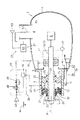
本実施形態のシール装置1は、上記空気チャンバー20内に加圧空気を供給する第一の空気供給手段26と、その空気チャンバー20内の空気圧P1よりも高い状態で喫水圧Pの変動に対応して変化する加圧空気をポッド4内に供給する第二の空気供給手段27と、を備えている。
【0024】
このうち、第一の空気供給手段26は、船体3内に配置されたコンプレッサー等よりなる第一の圧縮空気源28と、空気チャンバー20を区画する一対のシールリング13,14のうちの後部側の第二シールリング13から外部に空気が吹き出す程度に第一の圧縮空気源26からの加圧空気の圧力を設定する空気制御ユニット29と、この空気制御ユニット29を通過した加圧空気を空気チャンバー20に導く空気配管30とから構成されている。
空気制御ユニット29は、減圧弁31とその下流側に接続された流量調整弁32とを備えている。なお、本実施形態では、第一の圧縮空気源28として空気圧が7〜8(kg/cm2 )のものが使用され、この空気圧を減圧弁31で2〜3(kg/cm2 )程度に減圧している。また、流量調整弁32によって加圧空気の流量を10〜40(Nl/分)程度に設定して、空気チャンバー20に一定流量で加圧空気を送り込むことにより、第二シールリング13のリップ部から常に加圧空気を外部に向かって吹き出すようにしている。
【0025】
そして、シールリング13のガータスプリング23の締め付け力は概ね0.1(kg/cm2 )になっているから、外部水Wによるプロペラシャフト7の中心位置での喫水圧をP(kg/cm2 )とすると、上記した加圧空気の吹き出しにより、空気チャンバー20内の空気圧P1は、P+0.1(kg/cm2 )に設定され、喫水圧Pよりも常に一定の差圧だけ高い状態でかつその喫水圧Pの変動に対応した圧力に制御されることになる。
他方、第二の空気供給手段27は、船体3内に配置されたコンプレッサー等よりなる第二の圧縮空気源34と、空気配管30内の空気圧をパイロット圧として第二の圧縮空気源34からの加圧空気を所定の出力圧に設定するエアリレー35と、このエアリレー35で設定された出力圧をポッド4内に印加する加圧配管36と、を備えている。
【0026】
従って、上記エアリレー35の出力圧を空気チャンバー20内の空気圧P1よりも高めに設定することにより、空気チャンバー20内の空気圧P1よりも高い状態で喫水圧Pの変動に対応して変化する加圧空気をポッド4内に供給することができる。
なお、本実施形態では、エアリレー35の出力圧をパイロット圧に対して0.2(kg/cm2 )だけ高くなるように設定しており、このため、ポッド4の内部は、P1+0.2(kg/cm2 )=P+0.3(kg/cm2 )の圧力、すなわち、喫水圧Pに対して常に0.3(kg/cm2 )だけ高い状態に維持できるようになっている。
【0027】
また、本実施形態のシール装置1は、前記第二潤滑チャンバー22内に潤滑液体25を供給するためのオイルポンプ等よりなる液体供給手段37と、その供給によって空気チャンバー20内に漏洩してきた潤滑液体25や外部水Wを船内に回収するために当該空気チャンバー20に接続されたドレン回路38と、を備えている。このドレン回路38は、空気チャンバー20に接続された排出管路39と、船体3又はポッド4内に配置されたドレンタンク40とから構成されている。
【0028】
なお、液体供給手段37は、潤滑液体25を一定流量で常に少しずつ圧送するものであってもよいし、潤滑液体25を一定時間おきに間欠的に圧送するものであってもよい。また、ドレンタンク40や液体供給手段37は、ポッド4内に余裕があればその内部に設けることもできるが、船体3内に配置した方がポッド4のコンパクト化を図ることができる点で好ましい。
次に、上記構成に係るシール装置1の作用を説明する。
すなわち、本実施形態では、第一の空気供給手段26がポッド4の後部側に接続されたケーシング5の内部の空気チャンバー20内に加圧空気を供給しているので、この空気チャンバー20を区画するシールリング13,14のリップ部に作用する摺動負荷が低減し、そのシールリング13,14の耐久性が向上する。特に本実施形態では、第二シールリング13から常に加圧空気が吹き出しているので、そのリング13のリップ部がプロペラシャフト7の外周面に殆ど摺接しなくなり、このため、第二シールリング13の寿命を大幅に増大させることができる。
【0029】
他方、第二の空気供給手段27は、空気チャンバー20内の空気圧P1よりも高い状態で喫水圧Pの変動に対応して変化する加圧空気をポッド4内に供給しているので、上記のようにシールリング13,14のリップ部に作用する摺動負荷を低減させたことによって空気チャンバー20内に外部水Wが侵入してきても、その外部水Wが更にポッド4内に漏洩するのが有効に防止される。
このように、本実施形態のシール装置1によれば、第二の空気供給手段27によってポッド4内に外部水Wが漏洩するのを有効に防止しながら、第一の空気供給手段26によってポッド4の後部側に設けた空気チャンバー20に加圧空気を供給することでシールリング13,14のリップ部に作用する摺動負荷を低減させることができ、このため、ポッド1の内部機器の故障や腐食を伴わずにシールリング13,14の耐久性を向上させることができる。
【0030】
また、本実施形態によれば、第二潤滑チャンバー22内に潤滑液体25を供給する液体供給手段37を設けるとともに、空気チャンバー20にドレン回路38を接続しているので、潤滑液体25や外部水Wが空気チャンバー20内に漏洩してきてもそれらを船内に回収することができる。このため、潤滑液体25が外部に吹き出されることに伴う環境汚染を防止しながらシールリング14を潤滑状態にすることができる。
更に、本実施形態では、第一潤滑チャンバー21内の潤滑剤24が後部側に吹き飛ばされない程度の高粘性を有しているので、空気チャンバー20から空気が吹き出す程度に加圧空気の圧力を増大させた場合でも潤滑剤24が外部に飛散することがなく、この点でも環境汚染を未然に防止することができるし、油漏れの防止対策のために更に後部側にシールリングを追加する必要もなくなるので、シール装置1の軸方向寸法をコンパクト化することができる。
【0031】
図3は、第二循環チャンバー22の変形例を示している。
すなわち、この変形例では、第二循環チャンバー22を構成する第四シールリング15が、そのリップ部の先端縁が後部側に向くように配置されている。この場合、リップ部の先端縁同士が互いに向き合っている一対のシールリング14,15間で第二潤滑チャンバー22が区画されることになるので、潤滑液体25がポッド4側に漏洩するのをより有効に防止できるようになる。
もっとも、かかる構造の場合、液体供給手段37の圧送力によって第二循環チャンバー22の内部が高圧になり過ぎないように、安全弁41を第二潤滑チャンバー22に接続しておくことが必要であり、この安全弁41のリリーフ圧は、ポッド4内の空気圧P2よりも0.2(kg/cm2 )程度高いレベルに設定すればよい。
【0032】
図4は、本発明に係るシール装置1の第二の実施形態を示している。
上記第一の実施形態と本実施形態との主な相違点は、前者が、シールリングを通して加圧空気を吹き出すタイプであるのに対して、後者は、シールリングを通過させずに外部水Wに加圧空気を吹き出すことによって空気チャンバー内の空気圧を変更できるようになっている点にあり、その他の構成はほぼ同様である。
従って、以下においては、第一の実施形態と異なる点を重点的に説明し、構造ないし作用が同じ部材については図面に同じ参照符号を付することによって、重複説明を省略する。
【0033】
図4に示すように、本実施形態の第一の空気供給手段26は、船体3内に配置されたコンプレッサー等よりなる第一の圧縮空気源43と、この圧縮空気源43からの加圧空気を所定の圧力及び流量に設定する空気制御ユニット44と、この空気制御ユニット44を通過した加圧空気をシールリング12,13を通過させずに直接外部水Wに吹き出して喫水圧Pを検出する検出配管45と、この検出配管45内の空気圧をパイロット圧として第一の圧縮空気源43からの加圧空気を所定の出力圧に設定する第一のエアリレー46と、この第一のエアリレー46で設定された出力圧を空気チャンバー20内に印加する空気配管47と、を備えている。
【0034】
なお、本実施形態の空気制御ユニット44は、減圧弁48と、その下流側に接続された流量調整弁49と、上記第一のエアリレー46とを備えている。また、図例では、検出配管45の吹き出し口をケーシング5の基端部分に配置しているが、この吹き出し口をポッド4や船体3側に配置することもできる。
上記第一の空気供給手段43において、第一のエアリレー46の出力圧を検出配管45内の空気圧よりもガータスプリング23の締め付け力の分だけ高めに設定すれば、第一実施形態の場合と同様に、空気チャンバー20から加圧空気が吹き出す程度にその内部の空気圧を設定することができる。
【0035】
また、本実施形態の第一の空気供給手段43によれば、第一のエアリレー46の出力圧を検出配管45内の空気圧とほぼ同等かそれよりやや低い値に設定することもできる。この場合、空気チャンバー20から加圧空気が吹き出なくなるので、その吹き出しに伴って船外に潤滑液体25が漏洩するのを未然に防止できるとともに、空気消費量を可及的に低減できるという利点がある。
一方、第二の空気供給手段27は、船体3内に配置されたコンプレッサー等よりなる第二の圧縮空気源50と、検出配管45内の空気圧をパイロット圧として第二の圧縮空気源50からの加圧空気を所定の出力圧に設定する第二のエアリレー51と、この第二のエアリレー51で設定された出力圧をポッド4内に印加する加圧配管52と、を備えている。
【0036】
従って、かかる第二の空気供給手段27によれば、第二のエアリレー52の出力圧を空気チャンバー20内の空気圧P1よりも高めに設定することにより、空気チャンバー20内の空気圧P1よりも高い状態で喫水圧P1の変動に対応して変化する加圧空気をポッド4内に供給することができる。
なお、本発明は上記した各実施形態に限定されるものではなく、種々に変更することができる。例えば、第一シールリング12を省略して第一潤滑チャンバー21を設けない構造にすることもできる。
【0037】
また、上記実施形態では、船体3の船尾部分にポッドプロペラ推進システム2を設けているが、この推進システム2は、船体3の中央部や船首部分に設けることもできるし、海上に浮かぶ海底油田掘削プラントや空港等の種々の浮上構造物に設けることができる。
【0038】
【発明の効果】
以上説明したように、本発明によれば、ポッド内に外部水が漏洩するのを有効に防止しながらポッドの後尾部分に設けた空気チャンバーに加圧空気を供給できるので、ポッドの内部機器の故障や腐食を伴わずにシールリングの耐久性を向上させることができる。
【図面の簡単な説明】
【図1】第一実施形態のポッドプロペラ推進システムの概略側面図である。
【図2】第一実施形態のシール装置の側面断面図である。
【図3】第二潤滑チャンバーの変形例を示すためのケーシング内の断面図である。
【図4】第二実施形態のシール装置の側面断面図である。
【符号の説明】
1 シール装置
2 ポッドプロペラ推進システム
3 船体(浮上構造物)
4 ポッド
5 ケーシング
6 電動モーター
7 プロペラシャフト
12 第一シールリング
13 第二シールリング
14 第三シールリング
15 第四シールリング
20 空気チャンバー
21 第一循環チャンバー
22 第二循環チャンバー
24 潤滑剤
25 潤滑液体
26 第一の空気供給手段
27 第二の空気供給手段
28 第一の圧縮空気源
29 空気制御ユニット
30 空気配管
34 第二の圧縮空気源
35 エアリレー
36 加圧配管
37 液体供給手段
38 ドレン回路
43 第一の圧縮空気源
44 空気制御ユニット
45 検出配管
46 第一のエアリレー
47 空気配管
50 第二の圧縮空気源
51 第二のエアリレー
52 加圧配管[0001]
BACKGROUND OF THE INVENTION
The present invention relates to a sealing device for a pod propeller propulsion system.
[0002]
[Prior art]
In recent years, the power generated by the diesel engine in the hull is converted into an electric signal by an electric propulsion system, and this signal is transmitted by wire to an electric motor in a pod that is rotatably mounted on the stern part of the hull. A pod propeller propulsion system that rotates a propeller with a connected propeller shaft (for example, the product name “Adipod” from ABB Adipod) has been attracting attention. According to this system, the pod can be rotated outside the hull. There are various advantages such as no need for a steering machine and enhanced steering performance, electric propulsion can reduce noise and vibration in the ship, and the degree of freedom in design such as placing the engine on the bow side of the hull. It is said that there is.
[0003]
Of course, such a pod propeller propulsion system also requires a sealing device. In this case, the sealing device includes a pod that is provided on a floating structure such as a hull so as to be rotatable about a longitudinal axis, and a rear side of the pod. A cylindrical casing connected to the propeller shaft, a propeller shaft that is coaxially inserted into the casing and connected to an electric motor disposed in the pod, and slidably contacts the outer peripheral surface of the shaft to allow external water to flow. The thing provided with the some seal ring to seal is employ | adopted.
By the way, recently, due to an increase in the draft pressure accompanying the increase in size of the ship, there is a problem that the seal ring is damaged early and the lubricating oil leaks out of the ship, which leads to environmental pollution.
[0004]
Therefore, as a stern tube sealing device adopted in a normal marine vessel propulsion system that is not the pod propeller propulsion system, pressurized air is introduced into an air chamber partitioned between a pair of adjacent seal rings among a plurality of seal rings. The air is constantly blown out from the chamber toward the outboard water (see Japanese Utility Model Publication No. 5-35249, Japanese Patent Application Laid-Open No. 11-304005), and changes in response to fluctuations in draft pressure. By supplying pressurized air that is lower than the water pressure by a predetermined differential pressure into the air chamber (see Japanese Patent No. 2778899), the sliding load acting on the lip portion of the seal ring is reduced, and the durability of the seal ring is reduced. There is known an air seal type stern tube sealing device that improves the performance.
[0005]
[Problems to be solved by the invention]
Even in the conventional pod propeller propulsion system, it is necessary to overcome the problem that when the draft pressure increases as the size of the ship increases, the seal ring is damaged early and the lubricating oil leaks out of the ship, leading to environmental pollution. is there. Therefore, if the above-mentioned air seal type stern tube sealing device, which has been adopted in ordinary ship propulsion systems, is applied to the rear part of the pod that constitutes the pod propeller propulsion system, the durability of the seal ring can be improved. Conceivable.
[0006]
However, since the pod of the pod propeller propulsion system contains an electric motor that is vulnerable to water and a radial bearing that is easily corroded by seawater, the conventional air seal type stern tube sealing device was simply applied to the tail part of the pod. Alone, the pod propeller propulsion system can be fatally damaged.
In other words, when the air chamber partitioned in the tail part of the pod is pressurized to a level where air blows out from it or slightly lower than the draft pressure, the inside of the pod is also applied from the seal ring on the front side constituting the chamber. Because it is easy to blow out compressed air, external water that has entered the air chamber leaks into the pod together with the pressurized air, and this leaked water increases the risk of electric motor failure and corrosion of radial bearings. New challenges arise.
[0007]
In view of such circumstances, the present invention adopts an air seal type sealing device in a pod propeller propulsion system, and an air chamber provided on the rear side of the pod while effectively preventing external water from leaking into the pod. The purpose is to improve the durability of the seal ring without causing failure or corrosion of the internal equipment of the pod.
[0008]
[Means for Solving the Problems]
In order to achieve the above object, the present invention takes the following technical means.
That is, the present invention provides a first air supply means for supplying pressurized air into an air chamber defined between a pair of adjacent seal rings among a plurality of seal rings in the sealing device of the pod propeller propulsion system described above. And second air supply means for supplying pressurized air that changes in response to fluctuations in draft pressure in a state higher than the air pressure in the air chamber into the pod.
[0009]
According to the present invention described above, the first air supply means supplies pressurized air into the air chamber inside the casing connected to the rear side of the pod. Therefore, the lip portion of the seal ring that defines the air chamber The sliding load acting on the surface is reduced, and the durability of the seal ring is improved.
On the other hand, since the second air supply means supplies pressurized air that changes in response to fluctuations in draft pressure in a state higher than the air pressure in the air chamber, the lip of the seal ring as described above. By reducing the sliding load acting on the part, even if external water enters the air chamber, it is effectively prevented that the external water leaks into the pod.
[0010]
Thus, according to the present invention, while the second air supply means effectively prevents external water from leaking into the pod, the first air supply means adds to the air chamber provided on the rear side of the pod. By supplying compressed air, the sliding load acting on the lip part of the seal ring can be reduced, which can improve the durability of the seal ring without causing failure or corrosion of the internal equipment of the pod. it can.
Hereinafter, more preferred embodiments of the present invention will be described based on the contents of the dependent claims.
[0011]
In the present invention, in order to improve the life of the seal ring more reliably, it is necessary to lubricate the lip portion of the seal ring with a lubricating material such as grease or lubricating oil.
Therefore, a lubrication chamber is formed between a seal ring on the front side of the pair of seal rings that divides the air chamber and a seal ring disposed on the front side, and a lubricating liquid is contained in the lubrication chamber. It is recommended to provide a liquid supply means for supplying the liquid.
[0012]
If such a liquid supply means is provided, it is expected that the lubricating liquid and external water will leak into the air chamber, so a drain circuit for collecting them in the floating structure should be connected to the air chamber. Is preferred.
On the other hand, in order to keep the seal ring on the rear side of one of the seal rings defining the air chamber lubricated, the seal ring is defined between the seal ring and the seal ring disposed on the rear side. It is preferable to fill the lubrication chamber with a lubricant having such a high viscosity that the pressurized air blown out from the air chamber is not blown off to the rear side.
[0013]
In this case, since the lubricant in the lubrication chamber located on the rear side of the air chamber has such a high viscosity that it is not blown off to the rear side, the pressure of the pressurized air is increased to the extent that air is blown out from the air chamber. In this case, the lubricant is not scattered outside, and environmental pollution can be prevented. In addition, when the lubricant in the lubrication chamber is highly viscous as described above, it is not necessary to add a seal ring on the rear side to prevent oil leakage. There is also an advantage that can be made.
[0014]
In the present invention, when a sealing device that blows pressurized air through a seal ring is employed, a first compressed air source and a pair of seal rings that divide the air chamber are used as the first air supply means. An air control unit that sets the pressure of the compressed air from the compressed air source to such an extent that air is blown out from the rear side seal ring, and the compressed air that has passed through the air control unit is supplied to the air chamber. What is necessary is just to employ | adopt what is provided with the air piping led to.
In this case, since air is constantly blown out from the air chamber, the second compressed air source is used as the second compressed air source as the second compressed air source as the second compressed air source. If an air relay that sets the pressurized air of the air relay to a predetermined output pressure and a pressurized pipe that applies the output pressure set by the air relay into the pod is adopted, the output pressure of the air relay By setting the air pressure higher than the air pressure in the air chamber, it is possible to supply pressurized air that changes in response to fluctuations in the draft pressure in the pod in a state higher than the air pressure in the air chamber.
[0015]
In the present invention, when a seal device of a type that can change the air pressure in the air chamber is employed, the first compressed air source and the pressurized air from the compressed air source are used as the first air supply means. An air control unit that sets the air to a predetermined pressure and flow rate, a detection pipe that detects the draft pressure by blowing the pressurized air that has passed through the air control unit directly into the external water without passing through the seal ring, A first air relay that sets the pressurized air from the first compressed air source to a predetermined output pressure using the air pressure in the detection pipe as a pilot pressure, and the output pressure set by the first air relay as the air chamber What is necessary is just to employ | adopt what is provided with the air piping applied inside.
[0016]
In this case, if the output pressure of the first air relay is set higher than the air pressure in the detection pipe by an amount corresponding to the tightening force of the garter spring, the air pressure inside the air chamber can be set to the extent that air blows out. On the other hand, if the output pressure of the first air relay is set to a value approximately equal to or slightly lower than the air pressure in the detection pipe, pressurized air will not blow out from the air chamber. There is an advantage that leakage can be prevented and air consumption can be reduced.
[0017]
In this case, since it is also possible to perform control so that air does not always blow out from the air chamber, the second air supply means includes a second compressed air source, and a detection pipe. A second air relay that sets the pressurized air from the second compressed air source to a predetermined output pressure using the air pressure as a pilot pressure, and an application that applies the output pressure set by the second air relay to the pod. If the one with pressure piping is adopted, the output pressure of the second air relay is set higher than the air pressure in the air chamber, so that the draft pressure fluctuates in a state higher than the air pressure in the air chamber. Correspondingly changing pressurized air can be fed into the pod.
[0018]
DETAILED DESCRIPTION OF THE INVENTION
Hereinafter, embodiments of the present invention will be described with reference to the drawings.
1 to 3 show a first embodiment of a sealing device 1 according to the present invention.
As shown in FIG. 1, the sealing device 1 of this embodiment is used for a pod
[0019]
The front side end portion (right side end portion in FIG. 1) of the
The sealing device 1 of the present embodiment is an external sealing device arranged outside the rear side of the
[0020]
As shown in FIG. 2, the sealing device 1 includes a
Among these, the
[0021]
In this embodiment, a total of four
Among these, the
[0022]
The chamber defined between the
That is, the inside of the
[0023]
Further, the chamber defined between the
The sealing device 1 of the present embodiment copes with fluctuations in the draft pressure P in a state higher than the first air supply means 26 for supplying pressurized air into the
[0024]
Among these, the first air supply means 26 includes a first
The
[0025]
The tightening force of the
On the other hand, the second air supply means 27 is supplied from the second compressed air source 34 made of a compressor or the like disposed in the
[0026]
Therefore, by setting the output pressure of the
In the present embodiment, the output pressure of the
[0027]
Further, the sealing device 1 of the present embodiment includes a liquid supply means 37 including an oil pump for supplying the lubricating
[0028]
The liquid supply means 37 may be one that constantly pumps the lubricating
Next, the operation of the sealing device 1 according to the above configuration will be described.
That is, in the present embodiment, the first air supply means 26 supplies pressurized air into the
[0029]
On the other hand, the second air supply means 27 supplies the pressurized air that changes in response to the fluctuation of the draft pressure P in the
Thus, according to the sealing device 1 of the present embodiment, the first air supply means 26 effectively prevents the external water W from leaking into the
[0030]
Further, according to the present embodiment, the liquid supply means 37 for supplying the lubricating
Furthermore, in this embodiment, since the
[0031]
FIG. 3 shows a modification of the
That is, in this modification, the
However, in the case of such a structure, it is necessary to connect the
[0032]
FIG. 4 shows a second embodiment of the sealing device 1 according to the present invention.
The main difference between the first embodiment and the present embodiment is that the former is a type in which pressurized air is blown out through the seal ring, whereas the latter is the external water W without passing through the seal ring. The air pressure in the air chamber can be changed by blowing out pressurized air to the other, and other configurations are almost the same.
Therefore, in the following, points different from the first embodiment will be described with emphasis, and members having the same structure or function will be denoted by the same reference numerals in the drawings, and redundant description will be omitted.
[0033]
As shown in FIG. 4, the first air supply means 26 of the present embodiment includes a first
[0034]
The air control unit 44 of this embodiment includes a
In the first air supply means 43, if the output pressure of the
[0035]
Further, according to the first air supply means 43 of the present embodiment, the output pressure of the
On the other hand, the second air supply means 27 is supplied from the second
[0036]
Therefore, according to the second air supply means 27, the output pressure of the
In addition, this invention is not limited to each above-described embodiment, It can change variously. For example, the
[0037]
Moreover, in the said embodiment, although the pod
[0038]
【The invention's effect】
As described above, according to the present invention, it is possible to supply pressurized air to the air chamber provided in the rear part of the pod while effectively preventing external water from leaking into the pod. The durability of the seal ring can be improved without failure or corrosion.
[Brief description of the drawings]
FIG. 1 is a schematic side view of a pod propeller propulsion system according to a first embodiment.
FIG. 2 is a side sectional view of the sealing device of the first embodiment.
FIG. 3 is a cross-sectional view inside a casing for illustrating a modification of the second lubrication chamber.
FIG. 4 is a side sectional view of a sealing device according to a second embodiment.
[Explanation of symbols]
1 Sealing device
2 Pod propeller propulsion system
3 hull (floating structure)
4 Pods
5 Casing
6 Electric motor
7 Propeller shaft
12 First seal ring
13 Second seal ring
14 Third seal ring
15 Fourth seal ring
20 Air chamber
21 First circulation chamber
22 Second circulation chamber
24 Lubricant
25 Lubricating liquid
26 First air supply means
27 Second air supply means
28 First compressed air source
29 Air control unit
30 Air piping
34 Second compressed air source
35 Air Relay
36 Pressurized piping
37 Liquid supply means
38 Drain circuit
43 First compressed air source
44 Air control unit
45 Detection piping
46 First Air Relay
47 Air piping
50 Second compressed air source
51 Second air relay
52 Pressure piping
Claims (7)
前記複数のシールリング(12,13,14,15)のうち隣合う一対のシールリング(13,14)間で区画された空気チャンバー(20)内に加圧空気を供給する第一の空気供給手段(26)と、
前記空気チャンバー(20)内の空気圧(P1)よりも高い状態で喫水圧(P)の変動に対応して変化する加圧空気を前記ポッド(4)内に供給する第二の空気供給手段(27)と、
が設けられていることを特徴とするポッドプロペラ推進システムのシール装置。A pod (4) provided on the floating structure (3) so as to be rotatable about the longitudinal axis, a cylindrical casing (5) connected to the rear side of the pod (4), and the casing (5) A propeller shaft (7) that is coaxially inserted into the pod (4) and connected to an electric motor (6), and an outer water surface that is in sliding contact with the outer peripheral surface of the shaft (7). A seal device of a pod propeller propulsion system comprising a plurality of seal rings (12, 13, 14, 15) for sealing (W),
A first air supply that supplies pressurized air into an air chamber (20) defined between a pair of adjacent seal rings (13, 14) among the plurality of seal rings (12, 13, 14, 15). Means (26);
Second air supply means for supplying pressurized air that changes in response to fluctuations in draft pressure (P) in a state higher than the air pressure (P1) in the air chamber (20) into the pod (4). 27) and
A sealing device for a pod propeller propulsion system.
前記空気チャンバー(20)内に漏洩してきた前記潤滑液体(25)や外部水(W)を浮上構造体(3)内に回収するために当該空気チャンバー(20)に接続されたドレン回路(38)と、
が設けられていることを特徴とする請求項1に記載のポッドプロペラ推進システムのシール装置。Of the pair of seal rings (13, 14) defining the air chamber (20), a partition is formed between the seal ring (14) on the front side and the seal ring (15) disposed on the front side. Liquid supply means (37) for supplying a lubricating liquid (25) into the lubricated chamber (22),
A drain circuit (38) connected to the air chamber (20) for recovering the lubricating liquid (25) and external water (W) leaking into the air chamber (20) into the floating structure (3). )When,
The sealing device for a pod propeller propulsion system according to claim 1, wherein:
Priority Applications (1)
| Application Number | Priority Date | Filing Date | Title |
|---|---|---|---|
| JP2001339920A JP3668709B2 (en) | 2000-12-08 | 2001-11-05 | Seal device for pod propeller propulsion system |
Applications Claiming Priority (3)
| Application Number | Priority Date | Filing Date | Title |
|---|---|---|---|
| JP2000374745 | 2000-12-08 | ||
| JP2000-374745 | 2000-12-08 | ||
| JP2001339920A JP3668709B2 (en) | 2000-12-08 | 2001-11-05 | Seal device for pod propeller propulsion system |
Publications (2)
| Publication Number | Publication Date |
|---|---|
| JP2002234493A JP2002234493A (en) | 2002-08-20 |
| JP3668709B2 true JP3668709B2 (en) | 2005-07-06 |
Family
ID=26605519
Family Applications (1)
| Application Number | Title | Priority Date | Filing Date |
|---|---|---|---|
| JP2001339920A Expired - Lifetime JP3668709B2 (en) | 2000-12-08 | 2001-11-05 | Seal device for pod propeller propulsion system |
Country Status (1)
| Country | Link |
|---|---|
| JP (1) | JP3668709B2 (en) |
Families Citing this family (6)
| Publication number | Priority date | Publication date | Assignee | Title |
|---|---|---|---|---|
| EP2993123B1 (en) * | 2014-09-02 | 2017-03-08 | ABB Oy | Seal arrangement in a vessel |
| EP3015358B1 (en) * | 2014-11-03 | 2019-01-02 | ABB Oy | Seal arrangement for a propeller shaft |
| JP7251502B2 (en) * | 2020-03-11 | 2023-04-04 | Jfeスチール株式会社 | bearing device |
| EP4043335A1 (en) * | 2021-02-16 | 2022-08-17 | ABB Schweiz AG | Method and arrangement for sealing a propeller shaft located under water |
| EP4197898A1 (en) * | 2021-12-14 | 2023-06-21 | ABB Oy | Draining arrangement of a propulsion unit |
| CN114313189B (en) * | 2022-01-04 | 2024-03-01 | 武汉船用电力推进装置研究所(中国船舶重工集团公司第七一二研究所) | Sealing rim propeller |
-
2001
- 2001-11-05 JP JP2001339920A patent/JP3668709B2/en not_active Expired - Lifetime
Also Published As
| Publication number | Publication date |
|---|---|
| JP2002234493A (en) | 2002-08-20 |
Similar Documents
| Publication | Publication Date | Title |
|---|---|---|
| KR100301150B1 (en) | Lubrication unit for packing propeller drive mechanisms of ships equipped with two concentrically arranged double inverted propeller shafts | |
| JP6393833B2 (en) | Sealing structure for ship, propulsion device, ship and method for sealing propeller shaft of ship | |
| US4085941A (en) | Stern seals for ships | |
| CN111356631B (en) | Shaft seal device of double-reverse-rotation propeller device for ship | |
| EP1213221B1 (en) | Sealing device for pod propeller propulsion systems | |
| JP3668709B2 (en) | Seal device for pod propeller propulsion system | |
| JP2000238694A (en) | Stern tube sealing device | |
| JP3813842B2 (en) | Water lubricated stern tube sealing device | |
| JP2003127988A (en) | Sealing device for underwater structure | |
| US5795198A (en) | Floating seal for high rotational speed propeller shafts with integrated forced oil circulation generator and safety devices | |
| CN113825921B (en) | Sealing device | |
| JP3155505B2 (en) | Shaft sealing device for marine propulsion shaft | |
| JP2909948B2 (en) | Stern tube shaft sealing device | |
| JPH0972427A (en) | Stern pipe sealing device | |
| JP2005041348A (en) | Shaft seal device and shaft seal method for propeller shaft for ship | |
| JP3117333B2 (en) | Water supply to stern tube and shaft sealing / water supply device in contra-rotating propeller device | |
| JPH07242198A (en) | Stern tube sealing device | |
| JPH07242197A (en) | Stern tube sealing device | |
| JPH0717488A (en) | Stern tube shaft sealing device | |
| JP3693698B2 (en) | Device for sealing the end of a propeller shaft tube of a ship | |
| JP2005162066A (en) | Oiling device for stern tube | |
| JP2005133900A (en) | Stern tube sealing device | |
| JP2000065219A (en) | Bow side shaft sealing device for oil lubrication type stern tube bearing | |
| JP2003240130A (en) | Sealing device of underwater structure and assembly unit used in the same | |
| JP3229120B2 (en) | Lubricating device for sealing device of contra-rotating propeller shaft |
Legal Events
| Date | Code | Title | Description |
|---|---|---|---|
| A977 | Report on retrieval |
Free format text: JAPANESE INTERMEDIATE CODE: A971007 Effective date: 20050215 |
|
| TRDD | Decision of grant or rejection written | ||
| A01 | Written decision to grant a patent or to grant a registration (utility model) |
Free format text: JAPANESE INTERMEDIATE CODE: A01 Effective date: 20050405 |
|
| A61 | First payment of annual fees (during grant procedure) |
Free format text: JAPANESE INTERMEDIATE CODE: A61 Effective date: 20050411 |
|
| R150 | Certificate of patent or registration of utility model |
Ref document number: 3668709 Country of ref document: JP Free format text: JAPANESE INTERMEDIATE CODE: R150 Free format text: JAPANESE INTERMEDIATE CODE: R150 |
|
| FPAY | Renewal fee payment (event date is renewal date of database) |
Free format text: PAYMENT UNTIL: 20090415 Year of fee payment: 4 |
|
| R250 | Receipt of annual fees |
Free format text: JAPANESE INTERMEDIATE CODE: R250 |
|
| FPAY | Renewal fee payment (event date is renewal date of database) |
Free format text: PAYMENT UNTIL: 20090415 Year of fee payment: 4 |
|
| FPAY | Renewal fee payment (event date is renewal date of database) |
Free format text: PAYMENT UNTIL: 20100415 Year of fee payment: 5 |
|
| R250 | Receipt of annual fees |
Free format text: JAPANESE INTERMEDIATE CODE: R250 |
|
| FPAY | Renewal fee payment (event date is renewal date of database) |
Free format text: PAYMENT UNTIL: 20110415 Year of fee payment: 6 |
|
| R250 | Receipt of annual fees |
Free format text: JAPANESE INTERMEDIATE CODE: R250 |
|
| FPAY | Renewal fee payment (event date is renewal date of database) |
Free format text: PAYMENT UNTIL: 20110415 Year of fee payment: 6 |
|
| S533 | Written request for registration of change of name |
Free format text: JAPANESE INTERMEDIATE CODE: R313533 |
|
| FPAY | Renewal fee payment (event date is renewal date of database) |
Free format text: PAYMENT UNTIL: 20110415 Year of fee payment: 6 |
|
| R371 | Transfer withdrawn |
Free format text: JAPANESE INTERMEDIATE CODE: R371 |
|
| FPAY | Renewal fee payment (event date is renewal date of database) |
Free format text: PAYMENT UNTIL: 20110415 Year of fee payment: 6 |
|
| S533 | Written request for registration of change of name |
Free format text: JAPANESE INTERMEDIATE CODE: R313533 |
|
| FPAY | Renewal fee payment (event date is renewal date of database) |
Free format text: PAYMENT UNTIL: 20110415 Year of fee payment: 6 |
|
| R350 | Written notification of registration of transfer |
Free format text: JAPANESE INTERMEDIATE CODE: R350 |
|
| FPAY | Renewal fee payment (event date is renewal date of database) |
Free format text: PAYMENT UNTIL: 20120415 Year of fee payment: 7 |
|
| FPAY | Renewal fee payment (event date is renewal date of database) |
Free format text: PAYMENT UNTIL: 20130415 Year of fee payment: 8 |
|
| R250 | Receipt of annual fees |
Free format text: JAPANESE INTERMEDIATE CODE: R250 |
|
| S111 | Request for change of ownership or part of ownership |
Free format text: JAPANESE INTERMEDIATE CODE: R313111 |
|
| FPAY | Renewal fee payment (event date is renewal date of database) |
Free format text: PAYMENT UNTIL: 20130415 Year of fee payment: 8 |
|
| R350 | Written notification of registration of transfer |
Free format text: JAPANESE INTERMEDIATE CODE: R350 |
|
| FPAY | Renewal fee payment (event date is renewal date of database) |
Free format text: PAYMENT UNTIL: 20140415 Year of fee payment: 9 |
|
| R250 | Receipt of annual fees |
Free format text: JAPANESE INTERMEDIATE CODE: R250 |
|
| R250 | Receipt of annual fees |
Free format text: JAPANESE INTERMEDIATE CODE: R250 |
|
| R250 | Receipt of annual fees |
Free format text: JAPANESE INTERMEDIATE CODE: R250 |
|
| R250 | Receipt of annual fees |
Free format text: JAPANESE INTERMEDIATE CODE: R250 |
|
| R250 | Receipt of annual fees |
Free format text: JAPANESE INTERMEDIATE CODE: R250 |
|
| R250 | Receipt of annual fees |
Free format text: JAPANESE INTERMEDIATE CODE: R250 |
|
| R250 | Receipt of annual fees |
Free format text: JAPANESE INTERMEDIATE CODE: R250 |
|
| EXPY | Cancellation because of completion of term |