JP3668154B2 - Valve opener - Google Patents
Valve opener Download PDFInfo
- Publication number
- JP3668154B2 JP3668154B2 JP2001130272A JP2001130272A JP3668154B2 JP 3668154 B2 JP3668154 B2 JP 3668154B2 JP 2001130272 A JP2001130272 A JP 2001130272A JP 2001130272 A JP2001130272 A JP 2001130272A JP 3668154 B2 JP3668154 B2 JP 3668154B2
- Authority
- JP
- Japan
- Prior art keywords
- gear
- valve
- primary drive
- drive shaft
- air motor
- Prior art date
- Legal status (The legal status is an assumption and is not a legal conclusion. Google has not performed a legal analysis and makes no representation as to the accuracy of the status listed.)
- Expired - Lifetime
Links
Images


Classifications
-
- F—MECHANICAL ENGINEERING; LIGHTING; HEATING; WEAPONS; BLASTING
- F16—ENGINEERING ELEMENTS AND UNITS; GENERAL MEASURES FOR PRODUCING AND MAINTAINING EFFECTIVE FUNCTIONING OF MACHINES OR INSTALLATIONS; THERMAL INSULATION IN GENERAL
- F16K—VALVES; TAPS; COCKS; ACTUATING-FLOATS; DEVICES FOR VENTING OR AERATING
- F16K31/00—Actuating devices; Operating means; Releasing devices
- F16K31/02—Actuating devices; Operating means; Releasing devices electric; magnetic
- F16K31/04—Actuating devices; Operating means; Releasing devices electric; magnetic using a motor
- F16K31/046—Actuating devices; Operating means; Releasing devices electric; magnetic using a motor with electric means, e.g. electric switches, to control the motor or to control a clutch between the valve and the motor
-
- F—MECHANICAL ENGINEERING; LIGHTING; HEATING; WEAPONS; BLASTING
- F16—ENGINEERING ELEMENTS AND UNITS; GENERAL MEASURES FOR PRODUCING AND MAINTAINING EFFECTIVE FUNCTIONING OF MACHINES OR INSTALLATIONS; THERMAL INSULATION IN GENERAL
- F16K—VALVES; TAPS; COCKS; ACTUATING-FLOATS; DEVICES FOR VENTING OR AERATING
- F16K31/00—Actuating devices; Operating means; Releasing devices
- F16K31/02—Actuating devices; Operating means; Releasing devices electric; magnetic
- F16K31/04—Actuating devices; Operating means; Releasing devices electric; magnetic using a motor
- F16K31/047—Actuating devices; Operating means; Releasing devices electric; magnetic using a motor characterised by mechanical means between the motor and the valve, e.g. lost motion means reducing backlash, clutches, brakes or return means
-
- F—MECHANICAL ENGINEERING; LIGHTING; HEATING; WEAPONS; BLASTING
- F16—ENGINEERING ELEMENTS AND UNITS; GENERAL MEASURES FOR PRODUCING AND MAINTAINING EFFECTIVE FUNCTIONING OF MACHINES OR INSTALLATIONS; THERMAL INSULATION IN GENERAL
- F16K—VALVES; TAPS; COCKS; ACTUATING-FLOATS; DEVICES FOR VENTING OR AERATING
- F16K31/00—Actuating devices; Operating means; Releasing devices
- F16K31/44—Mechanical actuating means
- F16K31/53—Mechanical actuating means with toothed gearing
Description
【0001】
【発明の属する技術分野】
本発明はエアーモータで駆動されるバルブ開閉機に関する。より詳しくは配管等内の流体の遮断、通過、流量調整を行なうバルブを減速歯車を介してエアーモタで開閉するバルブ開閉機に関する。
【0002】
【従来の技術】
配管等内の流体の遮断、通過、流量調整を行なうバルブの開閉は人力、電気モータ等で行なわれている。しかし、石油、化学プラント等では防爆性に優れた工アーモータで駆動されるバルブ開閉機が多く用いられている。一般にバルブ開閉機の減速歯車はウオーム歯車が多く用いられるが効率が悪い欠点がある。又、バルブ全閉から開く時、バルブディスクとバルブボディ間の錆付きやカジリ等で作動不良がしばしば発生する。この対策として従来はバルブ開操作時にハンマーブローによる衝撃によって通常トルクの約5割増のトルクを与えていたが、このトルクは瞬間に作用するため確実性がなく信頼性が低いという欠点があった。
【0003】
【発明が解決しようとする課題】
本発明はかかる状況を鑑みて、バルブ全閉からの開操作を確実にして信頼性の向上を図り、小型で歯車効率の良いエアーモータ駆動式バルブ開閉機を提供することを課題とする。
【0004】
【課題を解決するための手段】
かかる課題を解決するために、本発明は1次駆動軸に回転自在に嵌合する高低速2個の1次駆動歯車を隣接して配設し、2次駆動軸に夫々の該1次駆動歯車に噛み合う被駆動歯と2次駆動歯を有する歯車を配設し、該各1次駆動歯車の内怪部に形成された各クラッチ歯の間を、エアーシリンダーによっていずれかのクラッチ歯と噛み合う1次駆動軸と1体化した突起を往復させる。バルブ全閉から開き始めの所定の距離は該突起が低速側の1次駆動歯車のクラッチ歯と噛み合って大きいトルクを発生させてバルブを確実に開き、所定の距離を過ぎた時点で該突起が高速側の1次駆動歯車のクラッチ歯と噛み合って通常のトルク、高速度でバルブの開操作を行なう。バルブを閉じる時は該突起は高速側の1次駆動歯車のクラッチ歯と噛み合い通常のトルク、高速度でバルブを閉じる。又、該各歯車は効率の良い平歯車系を使用した。
【0005】
【発明の実施の形態】
バルブ全閉から開く時、バルブディスクとバルブボディ間の錆付きやカジリによって開き難くなり、作動不良がしばしば発生している。この対策として、従来はバルブ開き始めにハンマーブローの衝撃によって通常トルクの約5割増しのトルクを与えていた。しかし、このトルクは瞬時に作用するため確実性がなく信頼性が低いという欠点があった。本発明ではこの対策としてバルブが開き始めるまでは約5割増しのトルクが継続して作用するようにした。又、駆動歯車内部にクラッチを内蔵して開閉機の小型化、平歯車を用いて伝達効率の向上を図った。以下、その一実施例を示し、本発明を詳細に説明する。
【0006】
【実施例】
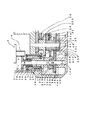
図1は本発明のバルブ開閉機の正面図を示し、図2は図1のA−A矢視図、図3はバルブの上部図を示す。図1において、本発明のバルブ開閉機1の原動機であるエアーモータ2はバルブ開閉機1の上部ケース3にボルト4で取付けられる。エアーモータ2の歯車2aの回転力は1次減速歯車部5、2次減速歯車部6、3次減速歯車部7を経て大歯車8に付勢される。
【0007】
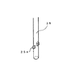
図3はバルブ9の上部図を示し、ヨーク10に回転自在に嵌合された雌ネジ11に回転せず上下のみ移行する雄ネジ12が係合している。従って、雌ネジ11が回転すると雄ネジ12が上下してバルブ9を開閉する。図4に示すように雌ネジ11の外周の一方には六角部11a、中心部に雌ネジl1bが加工されている。通常はバルブの手動ハンドルはこの六角部11aに取付けられるが、本発明のバルブ開閉機1を取付ける場合はこの六角部11aに図5に示すボス13を取付ける。図3において雌ネジ11の軸方向の移動は雌ネジ11の鍔部11cとカラー89、ボス13、座金14、ナット15によって制限される。
【0008】
図2にバルブ開閉機1とボス13の関係を示し、バルブ開閉機1の大歯車8の凹状穴8aとボス13の突起13aが係合して回転力を伝達する。又、本発明のバルフ開閉機1はバルブ9に図示しない取付け金具によって取付けられる。
【0009】
図1において大歯車8は上部ケース3と下部ケース16の軸穴3a、16aに回転自在に嵌合している。大歯車8の端面にはハンドル軸17がボルト18で取付けられている。手動ハンドル19の内径部は回転自在にハンドル軸17と嵌合して、手動時には連結ピン20でハンドル軸17と連結される。手動ハンドル19を使用しないときは、安全のために連結ピン20をハンドル軸17から抜いてハンドル軸17の回転力が手動ハンドル19に伝達しないようにする。連結ピン20はピン受け88内を摺動可能に支持されている。
尚、手動ハンドル19は上部ケース3にボルト21で取付けられるハンドル受け22に回転自在に嵌合し、軸芯方向の移動は止め輪23で制限される。上部ケース3と下部ケース16はパッキン24を介して図2に示すボルト94で固定される。
【0010】
図6は1次減速歯車部5の詳細図を示し、エアーモータ2の歯車2aには1次駆動軸25にピン26で固定された歯車27が噛み合っている。該軸25は軸受け28と下部ケース16の軸穴16aで支えられている。軸受け28はピストン29の内怪部に固定され、ピストン29が前進するとき1次駆動軸25と一緒に前進する。該軸25は上部ケース3に嵌着されているシリンダー30、低速側1次駆動歯車31、高速側1次駆動歯車32の中央穴31a、32aと該軸穴16aに回転自在及び軸方向摺動可能に配設されている。ピストン29の端面の空気室29aに図示しない空気穴から圧縮空気を供給するとピストン29は前進し、圧縮空気を排気するとバネ90によって後退する。
【0011】
図7に示すように1次駆動軸25の外怪部には突起25aが設けられ、該軸25が前進、後退すると該突起25aは図6に示す該歯車31又は該歯車32のクラッチ歯31b又は32bに係合して回転力を伝達する。該歯車31、該歯車32は2次減速歯車部6の歯車33の被駆動歯33a、33bと常時噛み合っている。従って、該歯車32より歯数の少ない該歯車31に該突起25aが係合すれば減速比は大きくなり、該突起25aが歯車32に係合すれは減速比は小さくなる。これらの減速比の比率は概ね5割増しである。このことはバルブ全閉から開き始めるときに有効に作用する。即ち、バルブ全閉から開き始めるときは図8に示すバルブディスク86とバルブボディ87の錆付きやカジリ等のため作動不良を起こす場合があるので一般にバルブ操作トルクを5割増しにする。尚、この方法のクラッチ機構84は従来のクラッチ機構に比較して非常に小型である.
【0012】
2次駆動軸34に回転自在に嵌合する歯車33の端部には3次減速歯車部7を駆動する2次駆動歯33cが歯車35の歯部35aと噛み合っている。図1、図6に示すように歯車35の他端の歯部35bは2次駆動軸34に回転自在に嵌合する歯車36の歯部36aに噛み合っている。歯車36の他端の歯部36bは駆動歯車として3次駆動軸37にキー38で廻り止めされている歯車39に噛み合っている。尚、歯車35は歯車39に対して回転自在である。又、3次駆動軸37にキー38で廻り止めされた歯車40によって大歯車8は回転力を伝達される。図1に示す3次駆動軸37は軸方向へ摺動可能に配設され、手動アーム41によって前進し、バネケース42内に収納されているバネ43によって後退する。手動ハンドル19でバルブ9を手動開閉するときは、該手動アーム41の軸41aを図示しないレバーで回転して3次駆動軸37を前進させて該キー38を歯車40から抜いて歯車40が3次駆動軸37に対して回転自在の状態にする。これによってバルブ9を手動開閉するときは大歯車8によって逆転される歯車は歯車40だけになるため、手動ハンドル19を軽く廻すことができる。
【0013】
歯車ケース44に軸支された3次駆動軸37は2次駆動軸34を中心に回転自在である。従って、図2において歯車40によって大歯車8が時計方向へ回転するとき3次駆動軸37と歯車ケース44は回転反力によって2次駆動軸34を中心に時計方向へ回転する。この回転反力は受け金45を介してバネ46、バネ受け93、ボルト47で支えられる。バネ46の力は使用前後はカバー92で保護されるボルト47で調節可能である。歯車ケース44の一端にはトルク検出アーム48がボルト49で取付けられ該トルク検出アーム48の先端で調整ボルト50を介してトルク検出弁51を作動させる。即ち、大歯車8の回転トルクが設定値に達したときトルク検出弁51が作動する。
【0014】
図2において、バルブ開閉検出機構52は大歯車8を駆動歯車として図示しない途中の減速機構によって駆動される。スライド軸53に固定されたストライカー54によってバルブ全開、全閉検出スイッチ55、56は作動する。スライド軸53はバネ57によって中立位置を保ち、該軸53に固定されたバルブ全閉検出アーム58又はバルブ全開検出アーム59が図示しない移動駒によって動かされることによって軸方向へ移動する。尚、検出アーム58、59はスライド軸53に図示しないセットネジによって任意の位置に固定できる。
【0015】
図9は本発明の空気制御系統図を示す。圧縮空気は空気源60から導管61、制止弁62、フイルター63、減圧弁64、導管65、給油器66、導管67を経て3位置4方弁68に入る。その後、導管69からエアーモータ2に入って導管70を通って該4方弁68から大気へ排出される。この場合、エアーモータ2は正転してバルブ9は開く。尚、圧縮空気が導管70から出るとこれらの関係は逆になりエアーモータ2は逆転してバルブ9は閉じる。
【0016】
導管65の圧縮空気は該4方弁68を操作するための3位置4方弁71、バルブ全閉検出スイッチ55、バルブ全開検出スイッチ56とクラッチシリンダー78を作動させるためのバネ式2位置3方弁85に入る。
該4方弁71を出た圧縮空気は導管72、74を経て該4方弁68の圧力作動アクチエーター68aに入って4方弁を正転位置に切り替えてエアーモータ2を正転させてバルブ9を開く。同様に圧縮空気が導管73、75を経て圧力作動アクチエーター68bに入るとエアーモータ2は逆転してバルブ9は閉じる。
尚、導管74の圧縮空気はバネ式2位置3方弁85の圧力作動アクチエーター85aにも流れ、クラッチシリンダー78が作動可能な状態にする。
バルブ全閉検出スイッチ55はバネ式2位置3方弁であり、バルブ9が全閉すると該検出スイッチ55が切り替わって圧縮空気は導管91に流れてトルク検出弁51、全閉表示ランプ76とクラッチシリンダー78を作動させるためのバネ式2位置3方弁77の圧力作動アクチエーター77aに入る。従って、クラッチシリンダー78が作動して該1次駆動軸25の突起25aが該低速側1次駆動歯車31のクラツチ歯31aに噛合って操作トルクが5割増しになる条件はバルブが開き始めるとき、即ちバルブ全閉から所定の距離開く場合である。この条件のとき以外はバルブ9を閉じる場合も含めて該突起25aは該高速側1次駆動歯車32のクラッチ歯32bに噛合い、通常操作トルクが作用し、バルブを高速開閉する。これによって、バルブを確実に且つ能率良く開閉することができる。
【0017】
トルク検出弁51はバネ式2位置3方弁であり、バルブ閉操作トルクが設定値に達すると圧縮空気は導管79から2位置4方弁80の圧力操作アクチエータ−80aに入って導管73から供給される圧縮空気を遮断してバルブ閉操作を停止する。
バルブ全開検出スイッチ56はバネ式2位置3方弁でありバルブ9が全開すると圧縮空気は導管81に流れて全開表示ランプ82を作動させると同時に2位置4方弁83の圧力作動アクチエー夕−83aに入って導管72から供給される圧縮空気を遮断してバルブ開操作を停止する。
尚、2位置4方弁80、83は開閉操作時に夫々の圧力作動アクチエータ−80b、83bに導管72、73から圧縮空気が入って切り替わり、操作前の原位置に復帰する。
【0018】
【発明の効果】
本発明によって、従来は減速歯車の外側にあったクラッチ機構を減速歯車の内部に組込むことによってバルブ開閉機を小型化することができた。又、バルブ全閉から開き始めるとき、バルブディスクとバルブボディの錆付きやカジリによる開操作不良に対して、従来はハンマーブロー効果によって瞬間的に約5割増しの操作トルクを作用させていたが、操作トルクは瞬間的に作用するため継続性がなく信頼性が低いという欠点があった。本発明では約5割増しトルクがバルブが全閉から開き始めるまでは継続して作用するため信頼性は非常に高くなる。又、従来のバルブ開閉機の減速歯車はウオーム歯車が主流で効率が低かったが、本発明では平歯車を使用しているため効率が高い。本発明は上記のような優れた効果を有する画期的な発明である。
【図面の簡単な説明】
【図1】本発明のバルブ開閉機の正面図である。
【図2】図1のA一A矢視図である。
【図3】バルブ上部図である。
【図4】雌ネジの姿図である。
【図5】ボスの姿図である。
【図6】1次減速歯車部の詳細図である。
【図7】1次駆動軸の姿図である。
【図8】バルブ下部図である。
【図9】本発明の空気制御系統図である。
【符号の説明】
1: バルブ開閉機
2: エアーモータ
2a: 歯車
3: 上部ケース
4: ボルト
5: 1次減速歯車部
6: 2次減速歯車部
7: 3次減速歯車部
8: 大歯車
9: バルブ
10: ヨーク
11: 雌ネジ
12: 雄ネジ
13: ボス
14: 座金
15: ナット
16: 下部ケース
17: ハンドル軸
19: 手動ハンドル
20: 連結ピン
22: ハンドル受け
25: 1次駆動軸
25a: 突起
27: 歯車
28: 軸受け
29: ピストン
30: シリンダー
31: 歯車
32: 歯車
33: 歯車
34: 2次駆動軸
35: 歯車
36: 歯車
37: 3次駆動軸
39: 歯車
40: 歯車
41: 手動アーム
42: バネケース
43: バネ
44: 歯車ケース
45: 受け金
46: バネ
48: トルク検出アーム
50: 調整ボルト
51: トルク検出弁
52: バルブ開閉検出機構
53: スライド軸
54: ストライカー
55: バルブ全閉検出スイッチ
56: バルブ全開検出スイッチ
57: バネ
58: バルブ全閉検出アーム
59: バルブ全開検出アーム
60: 空気源
61: 導管
63: フイルター
64: 減圧弁
65: 導管
66: 給油器
68: 3位置4方弁
68a: 圧力作動アクチエーター
71: 3位置4方弁
76: 全閉表示ランプ
77: バネ式2位置3方弁
78: クラッチシリンダー
79: 導管
80: 2位置4方弁
81: 導管
82: 全開表示ランプ
83: 2位置4方弁
84: クラッチ機構
85: バネ式2位置3方弁
86: バルブディスク
87: バルブボディ
88: ピン受け
89: カラー
90: バネ
91: 導管
92: カバー
93: バネ受け
94: ボルト[0001]
BACKGROUND OF THE INVENTION
The present invention relates to a valve opening / closing machine driven by an air motor. More specifically, the present invention relates to a valve opening / closing device that opens and closes a valve that performs blockage, passage, and flow rate adjustment of a fluid in a pipe or the like with an air motor via a reduction gear.
[0002]
[Prior art]
Valves that shut off, pass, and adjust the flow rate of fluid in piping and the like are opened and closed by human power, electric motors, and the like. However, in oil and chemical plants, etc., many valve opening / closing devices driven by an engineer motor having an excellent explosion-proof property are used. In general, a worm gear is often used as a reduction gear of a valve opening / closing device, but there is a disadvantage that the efficiency is poor. Also, when the valve is opened from the fully closed state, malfunctions often occur due to rusting or galling between the valve disk and the valve body. Conventionally, as a countermeasure, a torque that is about 50% higher than the normal torque is given by the impact of hammer blow when the valve is opened. However, since this torque acts instantaneously, there is a drawback that there is no certainty and the reliability is low.
[0003]
[Problems to be solved by the invention]
In view of such circumstances, it is an object of the present invention to provide an air motor-driven valve opening / closing device that is small and has high gear efficiency by ensuring the opening operation from fully closed valve and improving reliability.
[0004]
[Means for Solving the Problems]
In order to solve such a problem, the present invention has two primary drive gears that are rotatably fitted to the primary drive shaft so as to be rotatable, and each primary drive gear is disposed on the secondary drive shaft. A gear having a driven tooth and a secondary driving tooth meshing with the gear is disposed, and each clutch tooth formed in the internal defect portion of each primary driving gear meshes with any one of the clutch teeth by an air cylinder. The primary drive shaft and the integrated projection are reciprocated. The predetermined distance at which the valve starts to fully open after the valve is fully closed is that the protrusion meshes with the clutch teeth of the primary drive gear on the low speed side to generate a large torque, and the valve is reliably opened. Engage with the clutch teeth of the primary drive gear on the high speed side to open the valve at normal torque and high speed. When the valve is closed, the protrusion meshes with the clutch teeth of the primary drive gear on the high speed side to close the valve at a normal torque and a high speed. Each gear used an efficient spur gear system.
[0005]
DETAILED DESCRIPTION OF THE INVENTION
When the valve is opened from the fully closed position, it becomes difficult to open due to rust or galling between the valve disc and the valve body, and malfunctions often occur. As a countermeasure, conventionally, about 50% of the normal torque is applied by the impact of hammer blow at the beginning of valve opening. However, since this torque acts instantaneously, there is a drawback that there is no certainty and reliability is low. In the present invention, as a countermeasure, about 50% of torque is continuously applied until the valve starts to open. In addition, a clutch is built in the drive gear to reduce the size of the switch and to improve transmission efficiency by using a spur gear. Hereinafter, the present invention will be described in detail with reference to an example thereof.
[0006]
【Example】
FIG. 1 is a front view of a valve opening / closing device of the present invention, FIG. 2 is a view taken along the line AA of FIG. 1, and FIG. 3 is a top view of the valve. In FIG. 1, an
[0007]
FIG. 3 shows an upper view of the
[0008]
FIG. 2 shows the relationship between the valve opening /
[0009]
In FIG. 1, the
The
[0010]
FIG. 6 is a detailed view of the primary
[0011]
As shown in FIG. 7, the outer drive part of the
[0012]
A secondary drive tooth 33c for driving the tertiary
[0013]
A
[0014]
In FIG. 2, the valve opening /
[0015]
FIG. 9 shows an air control system diagram of the present invention. Compressed air enters the three-position four-
[0016]
The compressed air in the
The compressed air exiting the four-
The compressed air in the conduit 74 also flows to the pressure actuating actuator 85a of the spring type two-position three-
The valve full-close detection switch 55 is a spring-type two-position three-way valve. When the
[0017]
The
The valve full
The two-position four-
[0018]
【The invention's effect】
According to the present invention, it is possible to reduce the size of the valve opening / closing device by incorporating the clutch mechanism which has been conventionally outside the reduction gear into the reduction gear. In addition, when starting to open from the fully closed valve, the valve disk and valve body are rusted or poorly opened due to galling. Conventionally, an operating torque of about 50% was instantaneously applied due to the hammer blow effect. Since the operating torque acts instantaneously, there is a drawback that it is not continuous and has low reliability. In the present invention, since the torque continues to act until the valve starts to open from the fully closed state by about 50%, the reliability is very high. Moreover, the worm gear is the mainstream and the efficiency of the reduction gear of the conventional valve opening / closing machine is low, but in the present invention, the efficiency is high because a spur gear is used. The present invention is an epoch-making invention having the excellent effects as described above.
[Brief description of the drawings]
FIG. 1 is a front view of a valve switch according to the present invention.
FIG. 2 is a view taken along arrow A-1A in FIG. 1;
FIG. 3 is a top view of the valve.
FIG. 4 is a view of a female screw.
FIG. 5 is a view of a boss.
FIG. 6 is a detailed view of a primary reduction gear unit.
FIG. 7 is a view of a primary drive shaft.
FIG. 8 is a bottom view of the valve.
FIG. 9 is an air control system diagram of the present invention.
[Explanation of symbols]
1: Valve switch 2: Air motor 2a: Gear 3: Upper case 4: Bolt 5: Primary reduction gear 6: Secondary reduction gear 7: Tertiary reduction gear 8: Large gear 9: Valve 10: Yoke 11: Female thread 12: Male thread 13: Boss 14: Washer 15: Nut 16: Lower case 17: Handle shaft 19: Manual handle 20: Connection pin 22: Handle receiver 25: Primary drive shaft 25a: Projection 27: Gear 28 : Bearing 29: Piston 30: Cylinder 31: Gear 32: Gear 33: Gear 34: Secondary drive shaft 35: Gear 36: Gear 37: Tertiary drive shaft 39: Gear 40: Gear 41: Manual arm 42: Spring case 43: Spring 44: Gear case 45: Receptacle 46: Spring 48: Torque detection arm 50: Adjustment bolt 51: Torque detection valve 52: Valve open / close detection mechanism 53 : Slide shaft 54: Striker 55: Valve full close detection switch 56: Valve full open detection switch 57: Spring 58: Valve full close detection arm 59: Valve full open detection arm 60: Air source 61: Pipe 63: Filter 64: Pressure reducing valve 65 : Conduit 66: Refueling device 68: 3 position 4 way valve 68a: Pressure actuated actuator 71: 3 position 4 way valve 76: Fully closed indicator lamp 77: Spring type 2 position 3 way valve 78: Clutch cylinder 79: Conduit 80: 2-position 4-way valve 81: Conduit 82: Fully open indicator lamp 83: 2-position 4-way valve 84: Clutch mechanism 85: Spring-type 2-position 3-way valve 86: Valve disc 87: Valve body 88: Pin receiver 89: Color 90: Spring 91: Conduit 92: Cover 93: Spring receiver 94: Bolt
Claims (2)
Priority Applications (2)
| Application Number | Priority Date | Filing Date | Title |
|---|---|---|---|
| JP2001130272A JP3668154B2 (en) | 2001-04-26 | 2001-04-26 | Valve opener |
| KR10-2001-0047076A KR100520492B1 (en) | 2001-04-26 | 2001-08-03 | Valve Opening Shutting Switch |
Applications Claiming Priority (1)
| Application Number | Priority Date | Filing Date | Title |
|---|---|---|---|
| JP2001130272A JP3668154B2 (en) | 2001-04-26 | 2001-04-26 | Valve opener |
Publications (2)
| Publication Number | Publication Date |
|---|---|
| JP2002323164A JP2002323164A (en) | 2002-11-08 |
| JP3668154B2 true JP3668154B2 (en) | 2005-07-06 |
Family
ID=18978678
Family Applications (1)
| Application Number | Title | Priority Date | Filing Date |
|---|---|---|---|
| JP2001130272A Expired - Lifetime JP3668154B2 (en) | 2001-04-26 | 2001-04-26 | Valve opener |
Country Status (2)
| Country | Link |
|---|---|
| JP (1) | JP3668154B2 (en) |
| KR (1) | KR100520492B1 (en) |
Families Citing this family (3)
| Publication number | Priority date | Publication date | Assignee | Title |
|---|---|---|---|---|
| CN102927353B (en) * | 2012-11-15 | 2014-03-12 | 无锡智能自控工程股份有限公司 | Multi-rotary pneumatic executive regulator |
| KR101742475B1 (en) | 2015-07-20 | 2017-06-05 | (주)플로트론 | When adjusting the valve torque transmission for enforcement of the valve actuator |
| CN105587829A (en) * | 2015-12-17 | 2016-05-18 | 北京南口轨道交通机械有限责任公司 | Mechanical transmission system of drilling rig winch |
Family Cites Families (6)
| Publication number | Priority date | Publication date | Assignee | Title |
|---|---|---|---|---|
| JPS5712750Y2 (en) * | 1978-02-24 | 1982-03-13 | ||
| JPS6056842U (en) * | 1983-09-27 | 1985-04-20 | 日立建機株式会社 | Travel drive device for a traveling vehicle with a revolving body |
| JPH055350Y2 (en) * | 1985-10-08 | 1993-02-12 | ||
| JPH01156378U (en) * | 1988-04-21 | 1989-10-27 | ||
| JPH0735728Y2 (en) * | 1990-03-14 | 1995-08-16 | リョービ株式会社 | Shifting mechanism for polishing machine |
| JP2900280B2 (en) * | 1990-07-27 | 1999-06-02 | 株式会社 三協精機製作所 | Opening / closing drive |
-
2001
- 2001-04-26 JP JP2001130272A patent/JP3668154B2/en not_active Expired - Lifetime
- 2001-08-03 KR KR10-2001-0047076A patent/KR100520492B1/en active IP Right Grant
Also Published As
| Publication number | Publication date |
|---|---|
| JP2002323164A (en) | 2002-11-08 |
| KR20020083099A (en) | 2002-11-01 |
| KR100520492B1 (en) | 2005-10-11 |
Similar Documents
| Publication | Publication Date | Title |
|---|---|---|
| JP6520208B2 (en) | Electric valve actuator | |
| CN201281161Y (en) | Electric actuating unit for rotary motion valve | |
| CN203099040U (en) | Fault safety protection device used for fluid valve | |
| CN109681690A (en) | The deceleration device of valve intelligent actuator | |
| US4380325A (en) | Gas operated valve actuator | |
| US6585228B1 (en) | Electric valve actuator with eddy current clutch | |
| JP3668154B2 (en) | Valve opener | |
| CA1074778A (en) | Power tong apparatus | |
| US4611630A (en) | Single hydraulic line choke valve system | |
| CN2921505Y (en) | Valve electric device | |
| JP5493156B2 (en) | Electric valve actuator | |
| CN104100311A (en) | Hydraulic planetary drive type turning gear | |
| US2286597A (en) | Valve control | |
| US2251633A (en) | Valve control | |
| KR102223559B1 (en) | Declutchable unit apparatus for actuator | |
| RU92930U1 (en) | CONTROL DEVICE FOR PIPELINE CONTROL BODY | |
| RU179686U1 (en) | ELECTRIC PNEUMATIC SERVO DRIVE | |
| CA2781421A1 (en) | Actuating device for housed or unhoused valves | |
| JP3939120B2 (en) | Emergency shut-off valve device | |
| JPH07208638A (en) | Valve opening/closing device for tank in tanker | |
| RU2364780C1 (en) | Electric drive for stop valves | |
| US3172512A (en) | Positioning means for wire wrapping tool | |
| JP2003113811A (en) | Rotary valve device | |
| CN214037081U (en) | Variable speed ratio large torque valve driving device | |
| CN217842897U (en) | Marine valve hydraulic drive mechanism |
Legal Events
| Date | Code | Title | Description |
|---|---|---|---|
| A977 | Report on retrieval |
Free format text: JAPANESE INTERMEDIATE CODE: A971007 Effective date: 20041130 |
|
| A131 | Notification of reasons for refusal |
Free format text: JAPANESE INTERMEDIATE CODE: A131 Effective date: 20050114 |
|
| A521 | Written amendment |
Free format text: JAPANESE INTERMEDIATE CODE: A523 Effective date: 20050315 |
|
| TRDD | Decision of grant or rejection written | ||
| A01 | Written decision to grant a patent or to grant a registration (utility model) |
Free format text: JAPANESE INTERMEDIATE CODE: A01 Effective date: 20050404 |
|
| A61 | First payment of annual fees (during grant procedure) |
Free format text: JAPANESE INTERMEDIATE CODE: A61 Effective date: 20050407 |
|
| R150 | Certificate of patent or registration of utility model |
Ref document number: 3668154 Country of ref document: JP Free format text: JAPANESE INTERMEDIATE CODE: R150 Free format text: JAPANESE INTERMEDIATE CODE: R150 |
|
| FPAY | Renewal fee payment (event date is renewal date of database) |
Free format text: PAYMENT UNTIL: 20080415 Year of fee payment: 3 |
|
| FPAY | Renewal fee payment (event date is renewal date of database) |
Free format text: PAYMENT UNTIL: 20090415 Year of fee payment: 4 |
|
| R250 | Receipt of annual fees |
Free format text: JAPANESE INTERMEDIATE CODE: R250 |
|
| FPAY | Renewal fee payment (event date is renewal date of database) |
Free format text: PAYMENT UNTIL: 20090415 Year of fee payment: 4 |
|
| FPAY | Renewal fee payment (event date is renewal date of database) |
Free format text: PAYMENT UNTIL: 20090415 Year of fee payment: 4 |
|
| FPAY | Renewal fee payment (event date is renewal date of database) |
Free format text: PAYMENT UNTIL: 20100415 Year of fee payment: 5 |
|
| R250 | Receipt of annual fees |
Free format text: JAPANESE INTERMEDIATE CODE: R250 |
|
| FPAY | Renewal fee payment (event date is renewal date of database) |
Free format text: PAYMENT UNTIL: 20100415 Year of fee payment: 5 |
|
| FPAY | Renewal fee payment (event date is renewal date of database) |
Free format text: PAYMENT UNTIL: 20110415 Year of fee payment: 6 |
|
| R250 | Receipt of annual fees |
Free format text: JAPANESE INTERMEDIATE CODE: R250 |
|
| FPAY | Renewal fee payment (event date is renewal date of database) |
Free format text: PAYMENT UNTIL: 20110415 Year of fee payment: 6 |
|
| FPAY | Renewal fee payment (event date is renewal date of database) |
Free format text: PAYMENT UNTIL: 20120415 Year of fee payment: 7 |
|
| R250 | Receipt of annual fees |
Free format text: JAPANESE INTERMEDIATE CODE: R250 |
|
| FPAY | Renewal fee payment (event date is renewal date of database) |
Free format text: PAYMENT UNTIL: 20130415 Year of fee payment: 8 |
|
| R250 | Receipt of annual fees |
Free format text: JAPANESE INTERMEDIATE CODE: R250 |
|
| FPAY | Renewal fee payment (event date is renewal date of database) |
Free format text: PAYMENT UNTIL: 20130415 Year of fee payment: 8 |
|
| FPAY | Renewal fee payment (event date is renewal date of database) |
Free format text: PAYMENT UNTIL: 20140415 Year of fee payment: 9 |
|
| R250 | Receipt of annual fees |
Free format text: JAPANESE INTERMEDIATE CODE: R250 |
|
| R250 | Receipt of annual fees |
Free format text: JAPANESE INTERMEDIATE CODE: R250 |
|
| R250 | Receipt of annual fees |
Free format text: JAPANESE INTERMEDIATE CODE: R250 |
|
| R250 | Receipt of annual fees |
Free format text: JAPANESE INTERMEDIATE CODE: R250 |
|
| R250 | Receipt of annual fees |
Free format text: JAPANESE INTERMEDIATE CODE: R250 |
|
| R250 | Receipt of annual fees |
Free format text: JAPANESE INTERMEDIATE CODE: R250 |
|
| R250 | Receipt of annual fees |
Free format text: JAPANESE INTERMEDIATE CODE: R250 |
|
| R250 | Receipt of annual fees |
Free format text: JAPANESE INTERMEDIATE CODE: R250 |