JP3667056B2 - Clip removal tool - Google Patents
Clip removal tool Download PDFInfo
- Publication number
- JP3667056B2 JP3667056B2 JP31118197A JP31118197A JP3667056B2 JP 3667056 B2 JP3667056 B2 JP 3667056B2 JP 31118197 A JP31118197 A JP 31118197A JP 31118197 A JP31118197 A JP 31118197A JP 3667056 B2 JP3667056 B2 JP 3667056B2
- Authority
- JP
- Japan
- Prior art keywords
- clip
- tool
- plate
- shaped
- lining
- Prior art date
- Legal status (The legal status is an assumption and is not a legal conclusion. Google has not performed a legal analysis and makes no representation as to the accuracy of the status listed.)
- Expired - Fee Related
Links
Images


Classifications
-
- C—CHEMISTRY; METALLURGY
- C23—COATING METALLIC MATERIAL; COATING MATERIAL WITH METALLIC MATERIAL; CHEMICAL SURFACE TREATMENT; DIFFUSION TREATMENT OF METALLIC MATERIAL; COATING BY VACUUM EVAPORATION, BY SPUTTERING, BY ION IMPLANTATION OR BY CHEMICAL VAPOUR DEPOSITION, IN GENERAL; INHIBITING CORROSION OF METALLIC MATERIAL OR INCRUSTATION IN GENERAL
- C23C—COATING METALLIC MATERIAL; COATING MATERIAL WITH METALLIC MATERIAL; SURFACE TREATMENT OF METALLIC MATERIAL BY DIFFUSION INTO THE SURFACE, BY CHEMICAL CONVERSION OR SUBSTITUTION; COATING BY VACUUM EVAPORATION, BY SPUTTERING, BY ION IMPLANTATION OR BY CHEMICAL VAPOUR DEPOSITION, IN GENERAL
- C23C14/00—Coating by vacuum evaporation, by sputtering or by ion implantation of the coating forming material
- C23C14/22—Coating by vacuum evaporation, by sputtering or by ion implantation of the coating forming material characterised by the process of coating
- C23C14/34—Sputtering
- C23C14/3407—Cathode assembly for sputtering apparatus, e.g. Target
Description
【0001】
【発明の属する技術分野】
本発明は主に自動車の内張り等を固定しているクリップを容易に取り外す為のクリップ取り外し工具に関するものである。
【0002】
【従来の技術】
パワーウインドーの取り付けや修理時に、また事故などによる板金修理時等にドアやバックゲートの内側に取り付けられた装飾板、一般的に言うところの内張りを外す必要がある。
【0003】
内張りは、図7に示す様にクリップを介してボディーパネルに固定されている。
内張り6をボディーパネルから取り外すには、このクリップをボディーパネルに設けられた取り付け孔から抜き出せばよく、抜き出す工具としては図5に示すようなクリップ外し工具120が以前から存在する。
【0004】
クリップ外し工具は、U字状の嵌合溝を有する板状薄肉部を一端に設けた棒状の軸をドライバー等に用いているグリップに挿入したものであり、図5に示す様に軸部は先端から1/3あたりで略への字状にオフセット部126を設けて曲げてあって、この曲がりを支点として梃子の原理によりクリップを抜くものである。
【0005】
この様なクリップ外し工具の一般的な大きさは、全長が200mm程で、軸長が100mm程のものである。
【0006】
クリップの形状は図7に示すように、内張りに固定するためのプレートA43とプレートB44と、ボディーパネルに設けられた孔に挿入される楔状の弾性係合部42と、この弾性係合部42と一対となってボディーパネルを挟み込む傘状プレート41と、内張りに固定される為のプレートA43とプレートB44とから一般的に構成されている。
【0007】
内張り6におけるクリップ取り付け孔5は、クリップのプレートA43より若干大きめの孔51とクリップ軸部の径よりも若干大きめの孔52とからなる瓢箪状をしており、、クリップ4をまず大きい方の孔51に挿入した後、孔51と孔52の結合部はくびれを経て小さい方の孔52にスライドすることによりクリップ4は内張り6に固定されている。
【0008】
クリップ4をボディーパネルの孔から引き抜くには、傘状プレート41とプレートA43との間の溝45にクリップ引き抜き具120の先端二股部U字状溝121を挿入し、軸123の曲がりを利用して梃子操作により行っていた。
【0009】
しかしながら車両自体の形状が様々であり、当然のことながら内張りの形状及びその取り付け状態や周りの環境も様々であり、例えば図11に示す様に内張り6の外周61の他に、中央部辺り62にもクリップを使用して内張り6をより確実に固定させているものもある。
【0010】
内張り6の外周61に使用されているクリップ4については従来からあるクリップ外し工具でも外すことができるが、内張り中央部あたり62のクリップ4については、従来の取り外し工具の軸部の長さが短か過ぎてクリップ40に到達する事が出来なかったり、到達出来たとしてもボディーパネルと内張りとの限られた空間では梃子操作が出来ずに取り外すことが出来なかった。
【0011】
この様な場合には、クリップをボディーパネル取り付け孔から外すことにより内張りを取り外すのではなく、内張り自体を無理矢理引き上げて外さざる負えなかった。
【0012】
無理矢理引き上げて外した場合、内張りの瓢箪状のクリップ取り付け孔5を破損したり、クリップ4を破損してしまうことが多く、瓢箪状のクリップ取り付け孔5やクリップ4を破損させれば、内張りの建て付け状態が不完全になったり、走行時などの振動により異音を発生する原因にもなっていた。
【0013】
クリップの形状・大きさは車種により様々であり、極めて多くの種類のものが存在するため、一般的に整備工場では在庫を置かずに必要に応じて発注し入手しており、クリップを破損すれば修理期間が延長するばかりか、修理費として修理依頼者である車の持ち主に余計な金銭的な負担を強いるもとにもなっていた。
【0014】
また傘状プレート41とプレートA43との間の溝45は断面が略V字状である場合が多く、図11に示す様に板状薄肉部が四角断面の従来品では、薄肉部U字溝が十分に嵌合することができずに浅掛かりとなり、クリップを破損させてしまうことも多かった。
【0015】
【発明が解決しようとする課題】
本発明は、上記の問題点に鑑み、内張りのクリップ取り付け孔やクリップ自体を破損させることなく、内張りの中心部辺りに取り付けられたクリップをも取り外すことが出来るクリップ外し工具の提供を課題とするものである。
【0016】
【課題を解決するための手段】
前記従来品における課題は、次の通り本発明によって解決できる。
【0017】
即ち、本発明の第一のクリップ外し具は、U字状の嵌合溝21を有する板状薄肉部22を一端に設けた棒状のクリップ引き抜き具2と、クリップ引き抜き具2の下方に挿入し、クリップ引き抜き具2の先端方向に滑動することにより板状薄肉部22を上方に押し上げる為の先端略L字またはT字棒状の腕部31を有する押し上げ具3とを組み合わせたものである。
【0018】
また、本発明に係る第二のクリップ外し具は、第一のクリップ外し具の棒状の引き抜き具2を、オフセットのないストレート状とし、内張り中央部のクリップにも対応できる様に軸長を350mm以上としたものである。
【0019】
また、本発明に係る第三のクリップ外し具は、第一または第二のクリップ外し具の板状薄肉部22の傘状プレート嵌合面に、傘状プレート41に対応した凹部23を設けたものである。
【0020】
【発明の実施の形態】
以下、本発明の実施の形態を図面に基づき説明する。
【0021】
図3は、本発明のクリップ引き抜き具2の正面図であり、図5は従来品のクリップ引き抜き具の側面図であり、軸23の一端には板状の薄肉部22を設け、この薄肉部22にはクリップ4のプレートA43と傘状プレート41との間の溝45に係合出来る程度に薄肉状とし、且つU字状の嵌合溝22を設けてある。
【0022】
軸23は、オフセットを設けないストレート状としても、従来品同様に略への字状に曲げてもよいが、特に作業スペースが狭い場合には、ストレート状の物の方がより有効的である。
【0023】
U字状の嵌合溝21は、より多くのクリップの大きさに対応できる様に若干口開き状のU字状としてある。
【0024】
軸23のもう一端には、ドライバーハンドルに用いるハンドル24を樹脂成形してあり、より持ちやすく、また力が掛けやすくしてある。
【0025】
軸部の長さXは、内張りの中央辺りに使われているのクリップの取り外しを考慮して、350mm以上あることが好ましいが、350mm以下であってもクリップの取り付けられている位置によっては同様に押し上げ具を使用してのクリップ取り外し作業を行うことが出来、絶対的な条件ではない。
【0026】
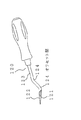
図4は、本発明の押し上げ具であり、丸または角棒状の軸33の一端にL字またはT字状の腕部を設けてあり、クリップ外し具2同様に軸部33の長さYが350mm以上あることが好ましく、また把持する為のグリップ34を一端に設けてある。
【0027】
押し上げ具の軸33は丸断面の棒でも角断面の棒でも差し支えないが、クリップ外し具の引き上げ量の関係上、5〜10mm程度の太さがあり、また腕部31にはクリップ外し具との位置関係を調整し、滑動操作や梃子操作が円滑に行える様に窪み35を設けることが好ましい。
【0028】
また、板状薄肉部22の傘状プレート嵌合面に傘状プレート41に対応した凹部24を設けることにより、クリップ4と板状薄肉部22が奥深くまで嵌合することが出来、浅係りによるクリップの破損を防ぐことが出来る。
【0029】
特に板状薄肉部22の厚みを1mm程度に薄く出来るので有れば図9に示す様に傘状又は球面状の凹部24とする必要はないが、一般的には強度的な問題により端に向かってテーパー状に薄肉部22を次第に薄くなる様にしてあり、傘状又は球面状のプレートに対応した凹部24を設けることに大きな効果がある。
【0030】
次に実際の取り外し手順を図面に基づき説明する。
【0031】
図11はバックゲート63の内張りの取り付け状態を示す図であり、内張りを取り外すにはまず外周のクリップを取り外すわけであるが、特に従来同様梃子の原理で取り外してもかまわない。
【0032】
次に中央あたり62のクリップを取り外す為にクリップ4のプレートAと傘状プレート41の間の溝45にクリップ引き抜き具先端薄肉部22を挿入嵌合させた後に、クリップ引き抜き具2の軸23に沿わして押し上げ具3の腕部31を挿入し、クリップ引き抜き具2の先端方向へ滑動すれば、腕部31がクリップ引き抜き具の先端に近付くにつれてクリップ引き抜き具2の板状薄肉部22が押し上げられ、クリップ4をボディーパネルに設けたクリップ取り付け孔から引き抜くことが出来る。
【0033】
作業スペースがあれば、押し上げ具3の腕部31を支点として梃子操作を行えばより容易にクリップを引き抜くことも可能である。
【0034】
従来品と本発明との作業スペースの比較を第9図に基づき説明する。
【0035】
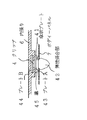
第8図はクリップ4の右側に本発明の取り外し状況を実線で、また左側に従来品による取り外し状況を想像線により示したものである。
【0036】
従来品においては梃子操作時のグリップ振り幅Zが必要となるのに対し、工具を挿入することのできるスペースさえ有れば取り外し作業が可能であり、従来に比し上下方向にW分の差がある小さなスペースであっても取り外し作業が可能である。
【0037】
【発明の効果】
以上説明したとおり、本発明の第一のクリップ外し具1は、U字状の嵌合溝21を有する板状薄肉部22を一端に設けた棒状のクリップ引き抜き具2と、クリップ引き抜き具2の下方に挿入し、クリップ引き抜き具2の先端方向へ滑動することにより板状薄肉部22を上方に押し上げる為の先端略L字またはT字棒状の腕部31を有する押し上げ具3とを組み合わせたことにより、内張りのクリップ取り付け孔やクリップ自体を破損させることなく、また内張りの中心部辺りに取り付けられたクリップの様に上下方向の作業スペースの極めて小さい場合にも取り外しを可能にし、また板状薄肉部22の傘状プレート嵌合面に傘状プレートに対応した凹部24を設けることにより確実にクリップをホールドすることが出来るクリップ外し工具である。
【0038】
従って、本発明の産業上利用性は非常に高いといえる。
【図面の簡単な説明】
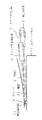
【図1】本発明に係るクリップ引き抜き具の下方に押し上げ具を挿入し、クリップ引き抜き具の先端付近まで滑動した状態を示す図。
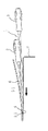
【図2】本発明に係るクリップ引き抜き具の下方に押し上げ具を挿入してクリップを引き抜く前段階の状態を示す図。(矢印は押し上げ具3の滑動方向を示す。)
【図3】本発明のクリップ引き抜き具や従来からのクリップ外し具を示す正面図。
【図4】本発明に係る押し上げ具の斜視図。
【図5】本発明のクリップ引き抜き具や従来からのクリップ外し具において、軸にオフセットを設けた状態を示す側面図。
【図6】内張りの瓢箪状のクリップ取り付け孔にクリップをスライド固定する状態を示す図。(矢印はクリップのスライド方向を示す。)
【図7】ボディーパネルにクリップにより内張りが固定されている状態を示す図。
【図8】本発明に係るクリップ外し具と従来品との作業スペースを比較する図。
【図9】クリップの傘状プレートに対応した凹部を設け板状薄肉部をクリップに嵌合させた状態を示す一部断面図。
【図10】従来品における板状薄肉部をクリップに嵌合させた状態を示す一部断面図。
【図11】内張りの中央にもクリップを使用しているバックドアの一例を示す図。
【符号の説明】
1 クリップ外し具
2 クリップ引き抜き具
21 U字状嵌合溝
22 板状薄肉部
23 軸(クリップ引き抜き具)
24 傘状凹部
25 クリップ引き抜き具ハンドル
3 押し上げ具
31 腕部
33 軸(押し上げ具)
34 クリップ押し上げ具ハンドル
35 窪み
4 クリップ
41 傘状プレート
42 弾性係合部
43 プレートA
44 プレートB
45 溝
5 瓢箪状クリップ取り付け孔
51 孔(大)
52 孔(小)
6 内張り
7 ボディーパネル
120 従来品のクリップ引き抜き具
121 従来品のクリップ引き抜き具におけるU字状嵌合
122 従来品のクリップ引き抜き具における板状薄肉部
123 従来品のクリップ引き抜き具における軸
124 従来品のクリップ引き抜き具における軸オフセット部
X クリップ引き抜き具の軸長
Y 押し上げ具の軸長
Z 従来品におけるグリップの振り幅(必要なスペース)
W 従来品と本発明との最低必要な作業環境の差[0001]
BACKGROUND OF THE INVENTION
The present invention mainly relates to a clip removal tool for easily removing a clip that fixes an automobile lining or the like.
[0002]
[Prior art]
When installing or repairing power windows, or when repairing sheet metal due to an accident, etc., it is necessary to remove the decorative plate attached to the inside of the door or back gate, generally called lining.
[0003]
The lining is fixed to the body panel via a clip as shown in FIG.
In order to remove the
[0004]
The clip removal tool is a tool in which a rod-shaped shaft provided with a plate-shaped thin wall portion having a U-shaped fitting groove at one end is inserted into a grip used for a driver or the like. As shown in FIG. An offset portion 126 is provided and bent in a substantially square shape around 1/3 from the tip, and the clip is pulled out by the lever principle with this bend as a fulcrum.
[0005]
The general size of such a clip removing tool has a total length of about 200 mm and an axial length of about 100 mm.
[0006]
As shown in FIG. 7, the clip has a plate A43 and a plate B44 for fixing to the lining, a wedge-shaped elastic engagement portion 42 inserted into a hole provided in the body panel, and this elastic engagement portion 42. And an umbrella-shaped plate 41 sandwiching the body panel, and a plate A43 and a plate B44 for fixing to the lining.
[0007]
The clip mounting hole 5 in the
[0008]
In order to pull out the
[0009]
However, the shape of the vehicle itself is various, and of course, the shape of the lining, its attachment state, and the surrounding environment are also various. For example, as shown in FIG. In some cases, the
[0010]
Although the
[0011]
In such a case, instead of removing the lining by removing the clip from the body panel mounting hole, the lining itself could not be removed by forcibly pulling it up.
[0012]
If it is pulled up and removed by force, the lining-like clip attachment hole 5 or the
[0013]
The shape and size of the clip varies depending on the type of vehicle, and there are many types of clips. Generally, a maintenance shop orders and obtains it as necessary without stocking it, and the clip is damaged. In addition to extending the repair period, the repair owner also imposed an extra financial burden on the owner of the car as the repair requester.
[0014]
Further, the groove 45 between the umbrella-shaped plate 41 and the plate A43 often has a substantially V-shaped cross section. As shown in FIG. 11, in the conventional product having a plate-shaped thin-walled section, the thin-walled section U-shaped groove. In many cases, however, the clip could not be sufficiently fitted, resulting in shallowness and damage to the clip.
[0015]
[Problems to be solved by the invention]
In view of the above problems, the present invention has an object to provide a clip removal tool that can also remove a clip attached around the center of the lining without damaging the clip attachment hole of the lining or the clip itself. Is.
[0016]
[Means for Solving the Problems]
The problems in the conventional products can be solved by the present invention as follows.
[0017]
That is, the first clip remover of the present invention is inserted into a bar-
[0018]
In addition, the second clip remover according to the present invention is such that the rod-
[0019]
Further, the third clip remover according to the present invention is provided with the concave portion 23 corresponding to the umbrella-like plate 41 on the umbrella-like plate fitting surface of the plate-like
[0020]
DETAILED DESCRIPTION OF THE INVENTION
Hereinafter, embodiments of the present invention will be described with reference to the drawings.
[0021]
FIG. 3 is a front view of the
[0022]
The shaft 23 may have a straight shape with no offset, but may be bent into a substantially square shape as in the conventional product, but a straight object is more effective especially when the work space is narrow. .
[0023]
The U-shaped
[0024]
At the other end of the shaft 23, a
[0025]
The length X of the shaft portion is preferably 350 mm or more in consideration of the removal of the clip used around the center of the lining. However, even if it is 350 mm or less, the length X is the same depending on the position where the clip is attached. The clip can be removed using a push-up tool, and this is not an absolute requirement.
[0026]
FIG. 4 shows a push-up tool according to the present invention, in which an L-shaped or T-shaped arm portion is provided at one end of a round or square rod-shaped shaft 33, and the length Y of the shaft portion 33 is the same as that of the
[0027]
The shaft 33 of the push-up tool can be either a round cross-section bar or a square cross-section bar, but has a thickness of about 5 to 10 mm due to the lifting amount of the clip remover. It is preferable to provide the
[0028]
Further, by providing the
[0029]
In particular, if the thickness of the plate-like
[0030]
Next, an actual removal procedure will be described with reference to the drawings.
[0031]
FIG. 11 is a view showing a state where the lining of the back gate 63 is attached. In order to remove the lining, the outer peripheral clip is first removed, but it may be removed by the lever principle as in the prior art.
[0032]
Next, in order to remove 62 clips around the center, after inserting and fitting the clip puller distal end
[0033]
If there is a work space, the clip can be pulled out more easily by performing the lever operation using the
[0034]
A comparison of the work space between the conventional product and the present invention will be described with reference to FIG.
[0035]
FIG. 8 shows the removal state of the present invention on the right side of the
[0036]
In the conventional product, the grip swing width Z at the time of lever operation is required, but if there is a space where the tool can be inserted, it can be removed, and the difference in W in the vertical direction compared to the conventional product Even a small space can be removed.
[0037]
【The invention's effect】
As described above, the
[0038]
Therefore, it can be said that the industrial applicability of the present invention is very high.
[Brief description of the drawings]
FIG. 1 is a view showing a state in which a push-up tool is inserted below a clip pulling tool according to the present invention and slid to the vicinity of the tip of the clip pulling tool.
FIG. 2 is a view showing a state before the clip is pulled out by inserting a push-up tool below the clip pull-out tool according to the present invention. (The arrow indicates the sliding direction of the push-up
FIG. 3 is a front view showing a clip pulling tool of the present invention and a conventional clip removing tool.
FIG. 4 is a perspective view of a push-up tool according to the present invention.
FIG. 5 is a side view showing a state in which an offset is provided on a shaft in the clip pulling tool of the present invention and the conventional clip removing tool.
FIG. 6 is a view showing a state in which a clip is slid and fixed in a lining-like clip attachment hole on the lining. (The arrow indicates the sliding direction of the clip.)
FIG. 7 is a view showing a state in which the lining is fixed to the body panel by a clip.
FIG. 8 is a diagram for comparing work spaces between a clip remover according to the present invention and a conventional product.
FIG. 9 is a partial cross-sectional view showing a state in which a concave portion corresponding to the umbrella-shaped plate of the clip is provided and a thin plate-like portion is fitted to the clip.
FIG. 10 is a partial cross-sectional view showing a state in which a plate-like thin portion in a conventional product is fitted to a clip.
FIG. 11 is a view showing an example of a back door using a clip also in the center of the lining.
[Explanation of symbols]
DESCRIPTION OF
24 Umbrella-shaped recessed part 25 Clip extraction tool handle 3 Push-
34 Clip push-up tool handle 35
44 Plate B
45 Groove 5 Gutter-shaped clip mounting hole 51 Large hole
52 holes (small)
6 Liner 7
W Difference in minimum working environment between conventional products and the present invention
Claims (3)
Priority Applications (2)
| Application Number | Priority Date | Filing Date | Title |
|---|---|---|---|
| JP31118197A JP3667056B2 (en) | 1997-10-27 | 1997-10-27 | Clip removal tool |
| PCT/JP1999/003480 WO2001000899A1 (en) | 1997-10-27 | 1999-06-29 | Sputtering target backing plate and sputtering target/backing plate assembly |
Applications Claiming Priority (2)
| Application Number | Priority Date | Filing Date | Title |
|---|---|---|---|
| JP31118197A JP3667056B2 (en) | 1997-10-27 | 1997-10-27 | Clip removal tool |
| PCT/JP1999/003480 WO2001000899A1 (en) | 1997-10-27 | 1999-06-29 | Sputtering target backing plate and sputtering target/backing plate assembly |
Publications (2)
| Publication Number | Publication Date |
|---|---|
| JPH11123665A JPH11123665A (en) | 1999-05-11 |
| JP3667056B2 true JP3667056B2 (en) | 2005-07-06 |
Family
ID=26440156
Family Applications (1)
| Application Number | Title | Priority Date | Filing Date |
|---|---|---|---|
| JP31118197A Expired - Fee Related JP3667056B2 (en) | 1997-10-27 | 1997-10-27 | Clip removal tool |
Country Status (2)
| Country | Link |
|---|---|
| JP (1) | JP3667056B2 (en) |
| WO (1) | WO2001000899A1 (en) |
Families Citing this family (5)
| Publication number | Priority date | Publication date | Assignee | Title |
|---|---|---|---|---|
| HUT40576A (en) * | 1984-09-21 | 1987-01-28 | Vnii Chistykh Bio | Process for producing human leucocite interferon |
| EP1715077A4 (en) | 2003-12-25 | 2010-09-29 | Nippon Mining Co | Copper or copper alloy target/copper alloy backing plate assembly |
| JP6915856B2 (en) * | 2017-07-20 | 2021-08-04 | 京都機械工具株式会社 | Clip removal tool |
| CN112406649B (en) * | 2019-08-22 | 2023-04-18 | Ykk株式会社 | Seat cover fastening clip |
| US11332056B2 (en) * | 2019-08-22 | 2022-05-17 | Ykk Corporation | Seat cover fastening clip |
Family Cites Families (4)
| Publication number | Priority date | Publication date | Assignee | Title |
|---|---|---|---|---|
| JPH0379734A (en) * | 1989-08-23 | 1991-04-04 | Sumitomo Kinzoku Kozan Shindo Hanbai Kk | Copper alloy for backing plate |
| JPH0448072A (en) * | 1990-06-14 | 1992-02-18 | Mitsui Mining & Smelting Co Ltd | Backing plate for sputtering target |
| JP3660014B2 (en) * | 1995-03-31 | 2005-06-15 | 株式会社テクノファイン | Sputtering target |
| JPH10330929A (en) * | 1997-05-28 | 1998-12-15 | Japan Energy Corp | Backing plate for sputtering target and sputtering target and backing plate assembled body |
-
1997
- 1997-10-27 JP JP31118197A patent/JP3667056B2/en not_active Expired - Fee Related
-
1999
- 1999-06-29 WO PCT/JP1999/003480 patent/WO2001000899A1/en active Application Filing
Also Published As
| Publication number | Publication date |
|---|---|
| JPH11123665A (en) | 1999-05-11 |
| WO2001000899A1 (en) | 2001-01-04 |
Similar Documents
| Publication | Publication Date | Title |
|---|---|---|
| US5495651A (en) | Hand tool for removing hoses | |
| US20080035900A1 (en) | Belt molding removal tool | |
| CA1260681A (en) | Clip removing tool | |
| US20080127473A1 (en) | Tool kit for removing decorative plates and trims of vehicles | |
| JP3667056B2 (en) | Clip removal tool | |
| US20130192040A1 (en) | Tool | |
| AU2020203595B2 (en) | Non-marring panel remover | |
| US4039140A (en) | Nail extractor | |
| US6216568B1 (en) | Pliers for removing knockouts | |
| US6260824B1 (en) | Board saver pry bar | |
| US20060032338A1 (en) | Device for assisting the removal of automobile hubs | |
| JPH09206833A (en) | Tool and metal pin for drawing motorcar repairing panel metal plate and panel metal plate drawing method using these | |
| US6052883A (en) | Broken key extractor | |
| US4120189A (en) | Pulling hook apparatus | |
| JP3060201U (en) | Nail hammer | |
| JP3055269U (en) | Tool for removing car lining materials | |
| JP3650093B2 (en) | Door molding remover | |
| JP2018071103A (en) | Construction and pull-out method of internal cone type post-construction anchor and construction and pull-out tool | |
| KR19980031514U (en) | Clip Removal Tool | |
| KR200148469Y1 (en) | Installing structure of regulator handle of door for a car | |
| JP3062535U (en) | Driving aid for anchor bolt with driving pin | |
| US8230565B2 (en) | Tool | |
| JPH11235681A (en) | Punch for nail puller | |
| FR2635711A1 (en) | Device used for nailing into hard materials | |
| JP2020175769A (en) | Foreign object removal tool for tire |
Legal Events
| Date | Code | Title | Description |
|---|---|---|---|
| A977 | Report on retrieval |
Free format text: JAPANESE INTERMEDIATE CODE: A971007 Effective date: 20041224 |
|
| A131 | Notification of reasons for refusal |
Free format text: JAPANESE INTERMEDIATE CODE: A131 Effective date: 20050208 |
|
| A521 | Written amendment |
Free format text: JAPANESE INTERMEDIATE CODE: A523 Effective date: 20050215 |
|
| TRDD | Decision of grant or rejection written | ||
| A01 | Written decision to grant a patent or to grant a registration (utility model) |
Free format text: JAPANESE INTERMEDIATE CODE: A01 Effective date: 20050329 |
|
| A61 | First payment of annual fees (during grant procedure) |
Free format text: JAPANESE INTERMEDIATE CODE: A61 Effective date: 20050405 |
|
| R150 | Certificate of patent or registration of utility model |
Free format text: JAPANESE INTERMEDIATE CODE: R150 |
|
| FPAY | Renewal fee payment (event date is renewal date of database) |
Free format text: PAYMENT UNTIL: 20080415 Year of fee payment: 3 |
|
| FPAY | Renewal fee payment (event date is renewal date of database) |
Free format text: PAYMENT UNTIL: 20110415 Year of fee payment: 6 |
|
| FPAY | Renewal fee payment (event date is renewal date of database) |
Free format text: PAYMENT UNTIL: 20110415 Year of fee payment: 6 |
|
| FPAY | Renewal fee payment (event date is renewal date of database) |
Free format text: PAYMENT UNTIL: 20130415 Year of fee payment: 8 |
|
| FPAY | Renewal fee payment (event date is renewal date of database) |
Free format text: PAYMENT UNTIL: 20130415 Year of fee payment: 8 |
|
| FPAY | Renewal fee payment (event date is renewal date of database) |
Free format text: PAYMENT UNTIL: 20140415 Year of fee payment: 9 |
|
| LAPS | Cancellation because of no payment of annual fees |