JP3667006B2 - Doctor holder - Google Patents
Doctor holder Download PDFInfo
- Publication number
- JP3667006B2 JP3667006B2 JP28184696A JP28184696A JP3667006B2 JP 3667006 B2 JP3667006 B2 JP 3667006B2 JP 28184696 A JP28184696 A JP 28184696A JP 28184696 A JP28184696 A JP 28184696A JP 3667006 B2 JP3667006 B2 JP 3667006B2
- Authority
- JP
- Japan
- Prior art keywords
- plate
- doctor blade
- doctor
- plate cylinder
- holder
- Prior art date
- Legal status (The legal status is an assumption and is not a legal conclusion. Google has not performed a legal analysis and makes no representation as to the accuracy of the status listed.)
- Expired - Lifetime
Links
Images


Landscapes
- Rotary Presses (AREA)
- Inking, Control Or Cleaning Of Printing Machines (AREA)
Description
【0001】
【発明の属する技術分野】
本発明は、印刷機やコーター、特に、グラビア印刷機やグラビアコーターにおいて、グラビアの凹版のセル以外に付着したインキをかき取るドクタリング機構に用いるドクタホルダに関する。
【0002】
【従来の技術】
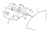
従来、グラビア印刷機は、図13〜図15に示すように、外周面に絵柄に対応したセル(凹部)を有する版胴1と、その版胴1にインキを供給するインキパン2と、版胴1のセル以外に付着したインキをかき取るドクタリング機構3と、印刷すべきウェブ4を版胴1に押し付ける圧胴5等を備えている。ドクタリング機構3は、ドクタ刃7と、そのドクタ刃7を保持するためのドクタホルダ8(詳細は後述)と、そのドクタホルダ8を支持して、軸線O−Oを中心として回転可能なホルダ台9と、そのホルダ台9に回転力Fを加えるエアシリンダなどの駆動機構(図示せず)等を備えており、そのホルダ台9に回転力Fを加えることによってドクタ刃7の先端を版胴1に押し付け、インキのかき取りを行っていた。
【0003】
ここで、ドクタ刃7は通常、幅50mm程度の帯状の平板で、基材として、高炭素鋼が使われており、ベース部の厚みは0.2mm程度であり、先端部分は2mm程度の長さで刃先加工がされている。刃先部分の厚みは0.1mm程度である。このドクタ刃7は、図14から良く分かるように、印刷版胴1の幅(軸線方向の長さ)よりも50mm程度長い幅に仕上げられている。ドクタホルダ8は、ドクタ刃7を上下からはさみ保持する上板11と下板12を有しており、両者は厚み10mm程度のアルミ合金で作られている。下板12は断面が長方形の帯状材の1面に大きく面取り加工を施したものである。上板11は、ドクタ刃7を版胴1に押し付けた際に、上方向への刃先のそりを支持するために、1面に鍔11aを備えている。この鍔11aは鋼材で別に作り、ねじ止めされるのが一般的である。上板11には幅方向に適当な間隔を開けて複数のボルト孔11bが形成されており、下板12にはそのボルト孔11bに対応する位置にねじ孔12bが形成され、締付ボルト13をボルト孔11bに通し且つねじ孔12bにねじ込むことにより、上板11と下板12とがドクタ刃7をはさんで締め付けられている。締付ボルト13は、ドクタホルダ8のサイズにもよるが、幅方向に5から10個程度設けられており、比較的短いピッチで上板11と下板12を締め付け、これによりドクタ刃7を幅方向に比較的均一な力で締め付け、固定している。ドクタ刃7は刃先が上板11の先端部よりも5〜10mm程度飛び出るようにセットされている。
【0004】
そして、使用に当たっては、ドクタ刃7を保持したドクタホルダ8をホルダ台9に取り付け、そのホルダ台9の位置を、ドクタ刃7が印刷に合わせたドクタ角度となるように設定し、また、版胴1の表面のインキのかき取りむらがないように、ドクタ刃7の版胴1に対する当たりの調整を行い(この調整はドクタホルダ8のホルダ台9に対する取り付け位置を調整することによって行う)、その後、ホルダ台9に回転力Fを加えて、ドクタ刃7の先端を版胴1に均一に押し付け、インキかき取りを行っていた。また、ホルダ台9をドクタ刃7の幅方向(版胴1の軸線に平行方向)に5mm程度往復動させ、ドクタ刃7の版胴1に対する幅方向の接触位置を変化させることも行われていた。
【0005】
【発明が解決しようとする課題】
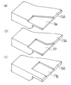
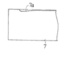
しかしなから、従来装置では上記したようにドクタ刃7を版胴1に対して均一に押し付けてインキのかき取りを行い、また、ドクタ刃7の往復動を行っているにもかかわらず、ドクタ刃7の刃先が局部的に磨耗するという現象があり、特に、図16に示すように、ドクタ刃7の両端近傍に局部摩耗部7aが生じていた。このような局部的な磨耗が著しくなると、版面上のインキのかき取り不良が起こるので、ドクタを交換しなければならないが、ドクタの交換は印刷機を停止させての作業であり、その交換作業には多くの準備時間がかかり、生産物の大幅な低下を招き、また、ドクタは消耗品であり、原材料費に占める割合が高く、結局印刷コストを高くするという問題となっていた。特に、最近は印刷物のカラー化が進み、グラビア印刷のほとんどが多色のカラー印刷となっているので、インキの色数だけ版胴とドクタが存在しており、ドクタ交換に伴う上記問題は重大な問題となっていた。
【0006】
本発明は、上述の問題点に鑑みて為されたもので、ドクタ刃の局部的な磨耗を防止し、ドクタ刃の寿命を長くすることの可能なドクタホルダを提供することを目的とする。
【0007】
【課題を解決するための手段】
本発明者らはドクタ刃に生じる局部的な磨耗を防止すべく検討した結果、この局部的な磨耗がドクタ刃の版胴の端部に接触する部分に生じており、これが以下の理由によって生じていることを見出した。すなわち、ドクタ刃にはドクタホルダを介して版胴に押し付けるための荷重がかけられ、版面に押し付けられているが、ドクタ刃は版胴幅よりも長く版胴の端部を越えて外側にまで延びているため、版胴の端部を越えた外側の部分では、ドクタ刃を受ける版面が無くなり、このため、版胴の端部では荷重が集中することとなる。このため、この部分ではドクタ刃の押付力が局部的に増大し、ドクタ刃の磨耗が著しく促進されていた。従って、この部分の押付力を低下させれば局部的な摩耗を抑制することができると考えられる。本発明はかかる知見に基づいてなされたもので、版胴幅よりも長いドクタ刃をドクタホルダで保持して版胴に押し付けた際に、版胴の端部に対応する部分のドクタ刃を上板で拘束せず、上板の方向に逃がすことができる構成とし、これによって版胴端部における荷重の集中を緩和し、ドクタ刃の局部磨耗を防止したものである。この構成により、版胴の端部に対応する部分でのドクタ刃の局部的な磨耗を低減させ、ドクタ刃の寿命を延長させ、印刷機の生産性を向上させることができる。
【0008】
【発明の実施の形態】
本発明の一つの実施形態では、版胴幅よりも長いドクタ刃を上板と下板で、はさみ保持する形式のドクタホルダにおいて、前記上板を、少なくとも版胴に対する側が版胴幅より短い寸法でドクタ刃を拘束する構造としたことを特徴とするものである。この構成により、ドクタホルダがドクタ刃を版胴に対して適当なドクタ角度で押し付けた際に、ドクタ刃の両端部を除いた部分では上板がドクタ刃を確実に押して版胴に押し付けるが、ドクタ刃の両端部分では上板の少なくとも版胴に対する側がドクタ刃を拘束していないため、ドクタ刃が上板の方向に逃げることができ、従って、版胴端部における荷重の集中を緩和し、ドクタ刃の局部磨耗を防止することができる。
【0009】
ここで、上板がドクタ刃を拘束しない領域は、版胴の側面に対応する部分から少なくとも内側に10mm以上に渡る範囲とすることが好ましい。また、上板がドクタ刃を拘束しない領域を形成するには、上板を全体的に切り欠いた形状としてもよいし、或いは上板のドクタ刃に面する面を凹んだ形状としてもよい。
【0010】
また、本発明の他の実施形態では、版胴幅よりも長いドクタ刃を少なくとも1枚の薄いあて板を介して上板と下板で、はさみ保持する形式のドクタホルダにおいて、前記上板とドクタ刃の間に位置する上部あて板を、少なくとも版胴に対する側において版胴幅より短い寸法としたことを特徴とするものである。この構成とすると、やはりドクタ刃の両端部分の少なくとも版胴に対する側が、上板及び上部当て板によって拘束されず、このため、ドクタ刃が上板の方向に逃げることができ、従って、版胴端部における荷重の集中を緩和し、ドクタ刃の局部磨耗を防止することができる。
【0011】
この場合においても、上部あて板の少なくとも版胴に対する側を、版胴の幅より片側10mm以上に渡り短い寸法とすることが好ましい。
【0012】
【実施例】
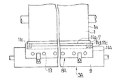
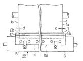
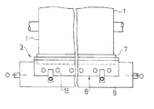
図1は本発明の一実施例によるドクタホルダを用いたドクタリング機構を示す概略平面図、図2はその主要部の概略側面図であり、図13〜図15に示す従来例と同一部品には同一符号を付して示している。図1、図2において、1は版胴、3Aは、版胴1のセル以外に付着したインキをかき取るドクタリング機構であり、ドクタ刃7と、そのドクタ刃7を保持したドクタホルダ8Aと、ドクタホルダ8Aを支持したホルダ台9等を備えている。ここで使用するドクタ刃7は従来と同一のものであり、版胴1の幅よりも少し(例えば、50mm程度)大きい長さのものであり、ドクタホルダ8Aをホルダ台9に取り付けた状態では、ドクタ刃7が版胴1の両側の側面1aよりも外側に延び出している。また、ホルダ台9にはエアシリンダ等の駆動機構が連結され、ドクタ刃7を版胴1に押し付けるための回転力Fが付与される構成となっている。
【0013】
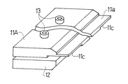
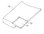
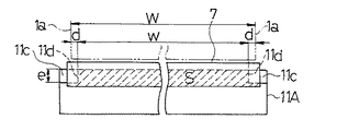
ドクタホルダ8Aは、ドクタ刃7を上下からはさみ保持する上板11A及び下板12と、この上板11Aと下板12とを一体に締め付ける締付ボルト13を有している。ここで、下板12は従来と同一構成のものである。上板11Aも、従来と同様に、ドクタ刃7を版胴1に押し付けた際に、上方向への刃先のそりを支持するための鍔11aを備えたものであるが、その下面(ドクタ刃7に面する面)の両端部で且つ版胴に対する側には従来と異なり、図3〜図5に示すように、1mm程度、平坦に凹んだ形状の凹部11cを形成している。このため、上板11Aがドクタ刃7に接触してドクタ刃7を拘束する領域は、図5に破線のハッチングで示す領域Sとなり、凹部11cに対応する領域は上板11Aで拘束されていない。ここで、凹部11cの形成位置は、その凹部11cの内側の側縁11dが版胴1の側面1aよりも内側となるように、従って、上板11Aがドクタ刃7に接触して拘束する領域の少なくとも版胴に対する側の長さwが、版胴幅Wよりも短い寸法となるように定められている。更に具体的には、凹部11cの内側の側縁11dと版胴1の側面1aとの間隔dが10mm以上、25mm以下となるように定められている。
【0014】
上記構成のドクタホルダ8Aも従来と同様にホルダ台9に取り付けられて使用される。すなわち、図1、図2に示すように、ドクタ刃7が版胴1に対して所定のドクタ角度となるようにホルダ台9の位置、角度が調整され、且つエアシリンダ等の駆動機構によってホルダ台9に矢印F方向の回転力が加えられ、それによってドクタ刃7の刃先が版胴1に押し付けられ、インキのかき取りが行われる。この時、上板11Aの鍔11aがドクタ刃7に接触し、拘束してこれを版胴1に押し付けるが、ドクタ刃7の両端部分は上板11Aに形成している凹部11cに面しているため、上板11Aでは拘束されず、このため、上板11A側に逃げることができ、この部分のドクタ刃7の版胴1に対する押付力は小さくなっている。一方、ドクタ刃7の版胴1の端部に接触する部分は、その外側にドクタ刃7を受ける版面がないため荷重の集中が生じて、押圧力が高くなる傾向があるが、前記したようにこの部分の押付力が小さくなっているため、結局、ドクタ刃7の版胴1の端部に接触する部分に過大な押付力が生じるという現象が回避される。かくして、ドクタ刃7の版胴端部に接触する部分に生じ勝ちなドクタ刃の局部磨耗が低減される。
【0015】
ここで、従来装置において、ドクタ刃7の版胴1の端部に接触する部分に生じていた局部磨耗は、5〜10mm幅程度であるため、上記したように、凹部11cの内側の側縁11dと版胴1の側面1aとの間隔dを10mm以上に設定しておけぱ、ドクタ刃7を5mm程度、往復動させた場合においても、局部磨耗を生じる恐れのある領域の押付力を低減させることができ、従って、局部磨耗を良好に防止できる。なお、この間隔dがあまり大きくなると、ドクタ刃7の中央領域の押付力が低下し、印刷領域におけるインキのかき取り不良を生じる恐れが生じるが、上記したように、25mm以下としておけば、印刷領域にほとんど影響を与えず、従って、印刷不良を生じることはない。
【0016】
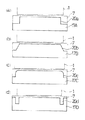
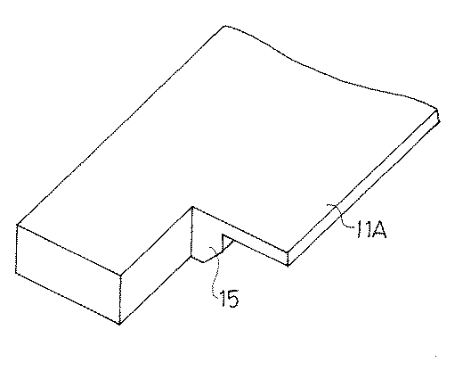
なお、凹部11cの奥行き方向の寸法e(図5参照)は、ドクタ刃7の版胴端部に接触する領域に荷重の集中によって生じる過大な荷重を緩和しうるように適当に定めればよい。更に、上記実施例では、凹部11cが一定深さに凹んだ浅い矩形状のものであるが、この形状は図示のものに限らず、ドクタ刃7を拘束せず、ドクタ刃7に生じる過大な荷重を緩和しうるものであれば任意である。例えば、図6(a)に示すように、斜めの側縁を有する凹部11e、図6(b)に示すように、円弧状の側縁を有する凹部11f、図6(c)に示すように、上板11Aの端部を残してその内側に形成した凹部11g等としてもよい。また、凹部11c、11e〜11g等は一定深さのものに限らず、深さが変化したものでもよく、更には、凹部に代えて、図7に示すように、切欠15を形成してもよい。
【0017】
上記実施例は、本発明をドクタ刃を上板と下板とで直接はさんで保持する形式のドクタホルダに適用したものである。ところで、この構成のドクタホルダでは、ドクタ刃をはさんだ上下の板が締付ボルトで締め付けられるが、上下板の厚さや材料強度の点から締付ボルトの位置で強く締め付けられ、締付ボルトから遠いほど締付力が低くなる現象が、程度の差はあるが、存在する。この影響でドクタ刃の刃先が波打ってしまい、真っ直ぐにセットできない不都合が生じることがある。この対策として、上板、下板とドクタ刃との間に、薄い(0.2〜1mm程度の)あて板を介在させ、これによってドクタ刃を補強し、刃先を真っ直ぐにセット可能とした形式のドクタホルダが知られている。本発明はこの形式のドクタホルダにも適用可能であり、図1〜図7に示す実施例において、ドクタ刃7と上板11A、下板12の間にそれぞれ、ドクタ刃7の全長に接触するように薄いあて板を介在させてもよい。更に、あて板を用いる場合には、あて板自体の形状を変え、上板としては下面に凹部等を形成していない従来と同様なものを用いることが可能である。以下、その場合の実施例を説明する。
【0018】
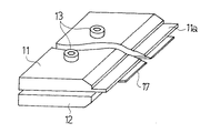
図8はその実施例によるドクタホルダ8Bを用いたドクタリング機構3Bを示す概略平面図、図9はその主要部の概略側面図、図9はそのドクタホルダ8Bの概略斜視図である。この実施例のドクタホルダ8Bは、ドクタ刃7をはさみ保持する上板11と下板12の他に、ドクタ刃7と上板11及び下板12の間にそれぞれ、上部あて板17と下部あて板18を配置している。ここで、上板11の下面(ドクタ刃7に面する面)には図1〜図7に示した実施例とは異なり、凹部は形成されていない。下部あて板18はドクタ刃7の全幅に渡ってドクタ刃7に接触して支持する長さを有しているが、上部あて板17は、図8から良く分かるように、版胴1の幅よりも短い長さのものであり、且つドクタ刃7に対して左右対称となる位置に配置されている。このため、ドクタ刃7の両端の版胴端部に対応する領域は、上部あて板17で拘束されていない。かくして、このドクタホルダ8Bをホルダ台9に取り付け、そのホルダ台9に矢印F方向の回転力を加えてドクタ刃7を版胴1に押し付けた時、ドクタ刃7の版胴端部に接触する部分における荷重の集中が緩和されて過大な押付力が作用せず、ドクタ刃7の局部的な磨耗を抑制できる。ここで、ドクタ刃7の版胴端部に当接する部分における過大な押付力を良好に防止するには、上部あて板17の側縁17aと版胴1の側面1aとの間隔dを10mm以上、25mm以下となるように定めることが好ましい。
【0019】
上記実施例では単純に上部あて板17の全長を短くしたが、この代わりに、上部あて板の版胴に対する側のみを短くして、ドクタ刃7の版胴端部に対応する部分の拘束を無くし、過大な押付力を抑制するようにすることも可能である。図12はその場合に使用する上部あて板の例を示すものである。図12(a)に示す上部あて板17Aは、版胴1に対する側の両端に矩形状の切欠20aを形成し、その上部あて板17Aを、版胴に対する側において版胴幅より短い寸法としたものである。図12(b)に示す上部あて板17Bは、版胴1に対する側の両端に傾斜した切欠20bを形成し、その上部あて板17Bを、版胴に対する側において版胴幅より短い寸法としたものである。図12(c)に示す上部あて板17Cは、版胴1に対する側の両端に円弧部を有する切欠20cを形成し、その上部あて板17Cを、版胴に対する側において版胴幅より短い寸法としたものである。図12(d)に示す上部あて板17Dは、版胴1に対する側の両端に、端縁から離れた領域に矩形状の切欠20dを形成し、その上部あて板17Dを、版胴に対する側において版胴幅より短い寸法としたものである。これらの上部あて板17A〜17Dもドクタ刃7の局部的な磨耗防止に有効である。
【0020】
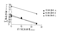
上部あて板を従来の形(ドクタ刃7の全幅に接触する長さ)とした場合(比較例)と、図8に示すように版胴1よりも片側で10mm狭幅とした場合(実施例1)、版胴1よりも片側で25mm狭幅とした場合(実施例2)のドクタ刃7の磨耗の程度を比較するため実際の印刷工程で検証実験を行った。その結果を表1及び図11のグラフに示す。
【0021】
【表1】
上記の検証実験は3つのそれぞれ印刷条件が異なるケースで行った。磨耗の程度は磨耗した部分の体積を測定することにより、数値化して評価している。この結果より明らかなように、上部あて板17を狭幅にしたことにより、磨耗量が著しく低減することが確認できた。また、短縮する長さとしては、片側10mm程度の短縮から効果が現れ始め、片側25mm短縮すると大きな効果が認められた。
【0023】
【発明の効果】
以上のように、本発明のドクタホルダは、ドクタ刃の版胴端部に接触する部分に加わる圧力の集中を排除することが可能であり、これによってドクタ刃の局部的な磨耗を従来に比べて極端に低減でき、その結果、ドクタ刃の寿命を延長でき、ドクタ刃の材料費の低減が可能であるばかりでく、印刷中におけるドクタ刃の交換時期が長くなり、印刷機を停止させる時間が短縮され、生産効率が上がるという大きな効果がある。
【図面の簡単な説明】
【図1】本発明の一実施例によるドクタホルダを用いたドクタリング機構を示す概略平面図
【図2】その主要部の概略側面図
【図3】上記実施例のドクタホルダの概略斜視図
【図4】上記実施例のドクタホルダの上板の端部裏面を示す概略斜視図
【図5】上記実施例におけるドクタ刃と上板との接触状態を説明する概略下面図
【図6】(a)、(b)、(c)はそれぞれ、上板11Aの裏面に形成する凹部の変形例を示す概略斜視図
【図7】上板の更に他の変形例を示す概略斜視図
【図8】本発明の他の実施例によるドクタホルダを用いたドクタリング機構を示す概略平面図
【図9】図8の実施例の主要部の概略側面図
【図10】図8の実施例のドクタホルダの概略斜視図
【図11】検証実験を行った結果を示すグラフ
【図12】(a)、(b)、(c)、(d)はそれぞれ、上部当て板の変形例を示す概略平面図
【図13】従来の印刷ユニットを示す概略側面図
【図14】従来のドクタリング機構を示す概略平面図
【図15】図14に示す装置の主要部の概略側面図
【図16】従来のドクタ刃に生じていた摩耗状態を示す概略平面図
【符号の説明】
1 版胴
3、3A、3B ドクタリング機構
7 ドクタ刃
8、8A、8B ドクタホルダ
9 ホルダ台
11、11A 上板
11c、11e、11f、11g 凹部
12 下板
17 上部あて板
18 下部あて板[0001]
BACKGROUND OF THE INVENTION
The present invention relates to a doctor holder used in a doctoring mechanism for scraping off ink adhering to cells other than gravure intaglio plates in a printing press and a coater, particularly a gravure printing press and a gravure coater.
[0002]
[Prior art]
Conventionally, as shown in FIGS. 13 to 15, the gravure printing machine includes a
[0003]
Here, the
[0004]
In use, the
[0005]
[Problems to be solved by the invention]
However, in the conventional apparatus, as described above, the
[0006]
The present invention has been made in view of the above-described problems, and an object of the present invention is to provide a doctor holder capable of preventing local wear of the doctor blade and extending the life of the doctor blade.
[0007]
[Means for Solving the Problems]
As a result of investigations to prevent local wear on the doctor blade, the present inventors have found that this local wear occurs in the portion of the doctor blade that contacts the end of the plate cylinder, which is caused by the following reason. I found out. In other words, the doctor blade is loaded with a load to press against the plate cylinder via the doctor holder and is pressed against the plate surface, but the doctor blade is longer than the plate cylinder width and extends outward beyond the end of the plate cylinder. Therefore, the plate surface that receives the doctor blade disappears in the outer portion beyond the end portion of the plate cylinder, so that the load is concentrated on the end portion of the plate cylinder. For this reason, the pressing force of the doctor blade locally increases in this portion, and the wear of the doctor blade is remarkably promoted. Therefore, it is considered that local wear can be suppressed by reducing the pressing force of this portion. The present invention has been made based on such knowledge, and when a doctor blade longer than the plate cylinder width is held by a doctor holder and pressed against the plate cylinder, a portion of the doctor blade corresponding to the end of the plate cylinder is placed on the upper plate. In this configuration, the load can be relieved in the direction of the upper plate without being restrained by the above, thereby reducing the concentration of the load at the plate cylinder end and preventing local wear of the doctor blade. With this configuration, it is possible to reduce the local wear of the doctor blade at the portion corresponding to the end portion of the plate cylinder, extend the life of the doctor blade, and improve the productivity of the printing press.
[0008]
DETAILED DESCRIPTION OF THE INVENTION
In one embodiment of the present invention, in a doctor holder in which a doctor blade longer than the plate cylinder width is held between the upper plate and the lower plate with scissors, the upper plate has a dimension at least on the side of the plate cylinder shorter than the plate cylinder width. The doctor blade is configured to restrain the doctor blade. With this configuration, when the doctor holder presses the doctor blade against the plate cylinder at an appropriate doctor angle, the upper plate reliably presses the doctor blade against the plate cylinder at the portion excluding both ends of the doctor blade. At both ends of the blade, at least the side of the upper plate relative to the plate cylinder does not restrain the doctor blade, so the doctor blade can escape in the direction of the upper plate, thus reducing the concentration of load at the end of the plate cylinder, The local wear of the blade can be prevented.
[0009]
Here, the region in which the upper plate does not restrain the doctor blade is preferably in a range extending at least 10 mm inward from the portion corresponding to the side surface of the plate cylinder. Moreover, in order to form the area | region where an upper board does not restrain a doctor blade, it is good also as a shape which notched the upper board as a whole, or good also as the shape which dented the surface which faces the doctor blade of an upper board.
[0010]
In another embodiment of the present invention, in the doctor holder of a type in which a doctor blade having a length longer than the plate cylinder width is held between the upper plate and the lower plate via at least one thin cover plate, the upper plate and the doctor are used. The upper cover plate positioned between the blades has a dimension shorter than the plate cylinder width at least on the side with respect to the plate cylinder. With this structure, at least the side of the both ends of the doctor blade with respect to the plate cylinder is not constrained by the upper plate and the upper plate, and therefore the doctor blade can escape in the direction of the upper plate. It is possible to alleviate the concentration of load at the part and to prevent local wear of the doctor blade.
[0011]
Even in this case, it is preferable that at least the side of the upper coating plate with respect to the plate cylinder is shorter than the width of the plate cylinder by 10 mm or more on one side.
[0012]
【Example】
FIG. 1 is a schematic plan view showing a doctor ring mechanism using a doctor holder according to an embodiment of the present invention, FIG. 2 is a schematic side view of the main part thereof, and the same parts as the conventional example shown in FIGS. The same reference numerals are given. 1 and 2, 1 is a plate cylinder, 3A is a doctoring mechanism for scraping ink adhering to other than the cells of the
[0013]
The
[0014]
The
[0015]
Here, in the conventional apparatus, the local wear that occurs in the portion of the
[0016]
Note that the depth dimension e (see FIG. 5) of the
[0017]
In the above embodiment, the present invention is applied to a doctor holder of a type in which a doctor blade is held directly between an upper plate and a lower plate. By the way, in the doctor holder of this configuration, the upper and lower plates sandwiching the doctor blade are tightened with the tightening bolts. There is a phenomenon that the tightening force is lowered as much as possible. Due to this influence, the blade edge of the doctor blade may be wavy and there may be a disadvantage that it cannot be set straight. As a countermeasure, a thin (about 0.2 to 1 mm) cover plate is interposed between the upper and lower plates and the doctor blade, which reinforces the doctor blade and allows the blade edge to be set straight. There are known doctor holders. The present invention is also applicable to this type of doctor holder. In the embodiment shown in FIGS. 1 to 7, the
[0018]
FIG. 8 is a schematic plan view showing a
[0019]
In the above embodiment, the total length of the
[0020]
When the upper plate is in a conventional shape (length contacting the full width of the doctor blade 7) (comparative example) and when it is narrower by 10 mm on one side than the
[0021]
[Table 1]
The verification experiment described above was performed in three cases with different printing conditions. The degree of wear is quantified and evaluated by measuring the volume of the worn portion. As is clear from this result, it was confirmed that the wear amount was remarkably reduced by narrowing the
[0023]
【The invention's effect】
As described above, the doctor holder of the present invention can eliminate the concentration of pressure applied to the portion of the doctor blade that contacts the plate cylinder end, thereby reducing the local wear of the doctor blade as compared with the conventional case. As a result, the life of the doctor blade can be extended, the material cost of the doctor blade can be reduced, the doctor blade replacement period during printing becomes longer, and the time to stop the printing press This has the great effect of shortening the production efficiency.
[Brief description of the drawings]
FIG. 1 is a schematic plan view showing a doctor ring mechanism using a doctor holder according to an embodiment of the present invention. FIG. 2 is a schematic side view of the main part. FIG. 3 is a schematic perspective view of a doctor holder according to the embodiment. FIG. 5 is a schematic bottom view illustrating the contact state between the doctor blade and the upper plate in the above embodiment. FIG. 6 (a), FIG. b) and (c) are schematic perspective views showing modified examples of the recesses formed on the back surface of the
DESCRIPTION OF
Claims (4)
Priority Applications (1)
| Application Number | Priority Date | Filing Date | Title |
|---|---|---|---|
| JP28184696A JP3667006B2 (en) | 1996-10-03 | 1996-10-03 | Doctor holder |
Applications Claiming Priority (1)
| Application Number | Priority Date | Filing Date | Title |
|---|---|---|---|
| JP28184696A JP3667006B2 (en) | 1996-10-03 | 1996-10-03 | Doctor holder |
Publications (2)
| Publication Number | Publication Date |
|---|---|
| JPH10109396A JPH10109396A (en) | 1998-04-28 |
| JP3667006B2 true JP3667006B2 (en) | 2005-07-06 |
Family
ID=17644829
Family Applications (1)
| Application Number | Title | Priority Date | Filing Date |
|---|---|---|---|
| JP28184696A Expired - Lifetime JP3667006B2 (en) | 1996-10-03 | 1996-10-03 | Doctor holder |
Country Status (1)
| Country | Link |
|---|---|
| JP (1) | JP3667006B2 (en) |
Families Citing this family (5)
| Publication number | Priority date | Publication date | Assignee | Title |
|---|---|---|---|---|
| CN106626754A (en) * | 2016-11-29 | 2017-05-10 | 湖州佳宁印刷有限公司 | Printing machine scraper adjusting device |
| CN106739476A (en) * | 2016-11-29 | 2017-05-31 | 湖州佳宁印刷有限公司 | Printing machine doctor mounting structure |
| CN106494081A (en) * | 2016-11-29 | 2017-03-15 | 湖州佳宁印刷有限公司 | The scraping blade for printing machine fixed structure of easy accessibility |
| JP6202458B1 (en) * | 2017-02-08 | 2017-09-27 | 下村 恭一 | Gravure printing plate, method for producing gravure printing plate and gravure printing method |
| KR102602019B1 (en) * | 2023-06-02 | 2023-11-13 | 김병주 | Package Film Manufacturing System That Can Reduce Hazardous Materials Using Ethanol Based Environmentally Friendly Ink And Gravure Roll With Low-Depth Cell |
-
1996
- 1996-10-03 JP JP28184696A patent/JP3667006B2/en not_active Expired - Lifetime
Also Published As
| Publication number | Publication date |
|---|---|
| JPH10109396A (en) | 1998-04-28 |
Similar Documents
| Publication | Publication Date | Title |
|---|---|---|
| US4184429A (en) | Constant bevel doctor blade and method and apparatus using same | |
| US4895071A (en) | Unitary doctor blade assembly | |
| US5656083A (en) | Chamber doctor | |
| JP3667006B2 (en) | Doctor holder | |
| US6305282B1 (en) | Doctor blade for wiping away excess printing ink from the surface of a printing form | |
| RU2238358C1 (en) | Composite squeegee and method for manufacturing the same | |
| US9643399B2 (en) | Ink feed device comprising an ink blade | |
| JP3667003B2 (en) | Doctor holder | |
| US20070181023A1 (en) | Ink fountain for a printing machine | |
| US9669614B2 (en) | Printing unit | |
| EP0339159A2 (en) | Varnish coating mechanism | |
| CN115107359A (en) | Scraper frame capable of quickly replacing scraping blade | |
| US12420542B2 (en) | Doctor | |
| JP2000062131A (en) | Doctor blade | |
| JPS61106254A (en) | Keyless inking apparatus | |
| US3244098A (en) | Anti-streaking printing plate having inner edge spaced from supporting surface | |
| JPH0623963A (en) | Weighing member | |
| RU26770U1 (en) | RAKEL KNIFE FOR FLEXOGRAPHIC CARS | |
| JPS63116852A (en) | Doctor blade | |
| JP2005103961A (en) | Cylinder of gravure printing machine | |
| JP2001276698A (en) | Roll coater device and coating method using the same | |
| JP2001080230A (en) | Doctor, gravure printing machine and printing method using these | |
| JP2620491B2 (en) | Cleaning equipment for blanket cylinders of printing presses | |
| EP1136273B1 (en) | Stencil printing apparatus | |
| JPH10100371A (en) | Cylindrical intaglio and its maintenance method |
Legal Events
| Date | Code | Title | Description |
|---|---|---|---|
| A977 | Report on retrieval |
Free format text: JAPANESE INTERMEDIATE CODE: A971007 Effective date: 20041111 |
|
| A131 | Notification of reasons for refusal |
Free format text: JAPANESE INTERMEDIATE CODE: A131 Effective date: 20041116 |
|
| A521 | Written amendment |
Free format text: JAPANESE INTERMEDIATE CODE: A523 Effective date: 20050114 |
|
| TRDD | Decision of grant or rejection written | ||
| A01 | Written decision to grant a patent or to grant a registration (utility model) |
Free format text: JAPANESE INTERMEDIATE CODE: A01 Effective date: 20050405 |
|
| A61 | First payment of annual fees (during grant procedure) |
Free format text: JAPANESE INTERMEDIATE CODE: A61 Effective date: 20050405 |
|
| R150 | Certificate of patent or registration of utility model |
Free format text: JAPANESE INTERMEDIATE CODE: R150 |
|
| FPAY | Renewal fee payment (event date is renewal date of database) |
Free format text: PAYMENT UNTIL: 20090415 Year of fee payment: 4 |
|
| FPAY | Renewal fee payment (event date is renewal date of database) |
Free format text: PAYMENT UNTIL: 20090415 Year of fee payment: 4 |
|
| FPAY | Renewal fee payment (event date is renewal date of database) |
Free format text: PAYMENT UNTIL: 20100415 Year of fee payment: 5 |
|
| FPAY | Renewal fee payment (event date is renewal date of database) |
Free format text: PAYMENT UNTIL: 20110415 Year of fee payment: 6 |
|
| FPAY | Renewal fee payment (event date is renewal date of database) |
Free format text: PAYMENT UNTIL: 20110415 Year of fee payment: 6 |
|
| FPAY | Renewal fee payment (event date is renewal date of database) |
Free format text: PAYMENT UNTIL: 20120415 Year of fee payment: 7 |
|
| FPAY | Renewal fee payment (event date is renewal date of database) |
Free format text: PAYMENT UNTIL: 20130415 Year of fee payment: 8 |
|
| FPAY | Renewal fee payment (event date is renewal date of database) |
Free format text: PAYMENT UNTIL: 20140415 Year of fee payment: 9 |
|
| EXPY | Cancellation because of completion of term |