JP3666773B2 - Floor heating panel - Google Patents
Floor heating panel Download PDFInfo
- Publication number
- JP3666773B2 JP3666773B2 JP07538697A JP7538697A JP3666773B2 JP 3666773 B2 JP3666773 B2 JP 3666773B2 JP 07538697 A JP07538697 A JP 07538697A JP 7538697 A JP7538697 A JP 7538697A JP 3666773 B2 JP3666773 B2 JP 3666773B2
- Authority
- JP
- Japan
- Prior art keywords
- panel
- plate
- heat medium
- floor heating
- adjacent
- Prior art date
- Legal status (The legal status is an assumption and is not a legal conclusion. Google has not performed a legal analysis and makes no representation as to the accuracy of the status listed.)
- Expired - Fee Related
Links
Images


Description
【0001】
【発明の属する技術分野】
本発明は床暖房用パネルに関するものである。
【0002】
【従来の技術】
近来、熱媒循環用パイプを設けたパネルユニットの複数を縦横に隣接させて所望の広さの床暖房用パネルを構成することが提案されている。
例えば、本出願人の先の出願、特願平8−242855号の願書に添付した明細書及び図面に示すものでは、各パネルユニットは、図18に示すように正方形の板状体aの4隅に切欠部bを設け、切欠部bの近傍下側に支持脚c(◎で位置を表示)を設置すると共に、熱媒循環用パイプdを蛇行させて1経路構成し、この熱媒循環用パイプdの両端部を一隅の切欠部bに位置させた構成である。このパネルユニットeでは、切欠部bの形状は、隅を直角に切り欠いた正方形の形状としている。
【0003】
この構成において、各パネルユニットeを、熱媒循環用パイプdの両端部が位置する夫々の一隅を対向させるように4つを1群として隣接すると、それらの切欠部bにより、切欠部の4倍の大きさの正方形状の空間部fが構成され、この空間部fにおいて、夫々の熱媒循環用パイプdの端部を熱源装置に連なる熱媒往き管、熱媒還り管のヘッダーh等に接続して、温水を循環供給させるようにしたり、隣接のパネルユニットeを帯板状金具等の接続用部材gにより接合する。
この後、空間部fを塞ぐために、図19に示すようにパネルユニットeの上側に捨張合板iを積層し、その上側にフローリング床等の仕上床材jを積層して床を構成している。
【0004】
【発明が解決しようとする課題】
捨張合板iは空間部fの上側にのみ対応して積層するのではなく、隣接したパネルユニットUの全体の上側に積層するので、空間部以外の部分では、板が重複する状態となる場合がある。
このため熱媒循環用パイプdから床の上面までの伝熱距離が長くなり、フローリング床等の仕上床材jの構成や厚みによっては、十分な熱性能が得られなくなる他、コストアップの要因ともなっている。
本発明では、このような課題を解決することを目的とするものである。
【0005】
【課題を解決するための手段】
上述した課題を解決するために、本発明では、正方形の板状体の隅部に直角二等辺三角形状の切欠部を設け、切欠部の端縁から内側に低段部を構成すると共に、熱媒循環用パイプを、その端部を切欠部に配置してパネルユニットを構成し、このパネルユニットの複数を縦横に隣接させて所望の広さに構成すると共に、向かい合った切欠部により空間部を構成するものとし、この空間部に至る熱循環用パイプを装着する板状体上面の溝に傾斜部を形成し、この空間部の周囲に形成される低段部に、その深さと同じ厚さの接合板を嵌合し、接合板を各パネルユニットに固定することにより隣接するパネルユニットを接合して、パネル表面と段差のない表面を構成することを提案する。
【0006】
本発明において、切欠部は、従来と同様に板状体の隅を直角に切り欠いた正方形状に構成する他、板状体の隅を斜めに切り欠いた直角二等辺三角形状に構成することができる。
【0007】
また本発明において、切欠部は板状体の全ての隅に設ける他、板状体の隣接する2隅にのみ設けることができる。
【0008】
以上の本発明では、切欠部は板状体の4隅に設けた構成の他、隣接する2隅にのみ設けた構成とすることができる。
【0009】
以上の本発明によれば、接合板を空間部の周囲の低段部に嵌合して各パネルユニットに固定すれば、接合板は、空間部を塞ぐと同時に隣接した4つのパネルユニットを接合し、更に、各パネルユニットの上面と接合板の上面を同一平面上とすることができるので、捨張合板を積層せずに仕上床板を積層することができる。
【0010】
【発明の実施の形態】
次に本発明の実施の形態を図を参照して説明する。
まず、図1は本発明を適用するパネルユニットUの実施の形態を示す平面図であり、図2は図1のA−A線断面図である。また、図3は図1のパネルユニットUの複数を縦横に隣接させて構成した床暖房用パネルの一部を模式的に示す平面図である。
符号1は板状体であり、この板状体1は正方形であって、各隅には、斜めに切り欠いた直角二等辺三角形状の切欠部2(2a,2b,2c,2d)を設けており、この切欠部2の端縁から内側に低段部7を構成している。
図2に示すように板状体1の上面には、隣接する切欠部2に夫々の端部が位置するように複数の溝4を形成しており、これらの夫々に熱媒循環用パイプ3を装着することにより、熱媒循環用パイプ3を4経路構成するものとしている。
即ち、熱媒循環用パイプ3は切欠部2a,2b;2b,2c;2c,2d;2d,2a間の溝4に夫々装着して、経路3a;3b;3c;3dの4経路構成していて、それらの経路の熱媒循環用パイプ3の両側の夫々の端部は、切欠部2a,2b;2b,2c;2c,2d;2d,2aに位置させている。
これらの熱媒循環用パイプ3の4経路のうち、経路3dは蛇行させた構成とすると共にその他の経路3a,3b,3cは直線状経路として構成している。
各熱媒循環用パイプ3の経路の形状は適宜であり、またこれらの熱媒循環用パイプ3の端部は、図示は省略しているが、後述する接続用部材及び供給用部材に接続可能とするように切欠部2の面から外側に適宜長突出させる等、接続が容易な構成とすることができる。
板状体1は、床の荷重を支えることができる材質であれば、木質合板、パーチクルボード、発泡プラスチックス板またはこれらの複合体等の適宜の材質のものを適用することができる。
また板状体1の切欠部2は、上述したように板状体1の隅を斜めに切り欠いた直角二等辺三角形状に構成する他、図17、図18に示すように、従来と同様な形状、即ち、板状体1の隅を直角に切り欠いた正方形状に構成することもできる。
熱媒は、例えば温水であり、この場合、熱媒循環用パイプ3は、例えば架橋ポリエチレン等の、耐圧、耐熱、耐久性に優れた材質のパイプを使用することができる。
さらに板状体1に熱媒循環用パイプ3を支持する構成は、上記のように溝4に熱媒循環用パイプ3を一面側から装着して支持する構成の他、板状体1内に埋め込んで支持する構成とすることもできる。
一方、この実施の形態では、板状体1の下側の図中◎印で示す位置、即ち、4隅の切欠部2(2a,2b,2c,2d)の近傍位置と、各隅間の中間位置と、中心位置の夫々に支持脚5を配置する構成としている。この他、支持脚5を配置する位置は、少なくとも4隅の切欠部2(2a,2b,2c,2d)の近傍位置に設ける他は、上述した位置以外の適所に設定することができ、また場合によっては、支持脚を設けない床暖房用パネルとすることもできる。
【0011】
以上の構成において、複数のパネルユニットUを縦横に隣接させて配置すると、図3〜図5に示すように向かい合った夫々の切欠部2により、パネルユニットUの形状に対して45゜回転した形状の正方形状の空間部Sが形成される。従って、この空間部Sにおいて、各経路3a,3b,3c,3dの熱媒循環用パイプ3の所定の端部相互間を接続用部材10により接続して各経路を連通させ、所定の対を成す各経路の熱媒循環用パイプ3の端部を、熱源装置に連なる熱媒往き管11と熱媒還り管12に接続した供給用部材13に接続して熱媒を循環供給可能に構成すると共に、隣接のパネルユニットU間を接合して所定の広さの床暖房用パネルを構成することができる。
【0012】
隣接のパネルユニットU間の接合は、上記低段部7により空間部Sの周縁に形成される正方形状の低段部に、図5に示すように接合板6を嵌合して、釘等で板状体1に固定することにより行う。
このような接合方法を適用するために、溝4には図6に示すように低段部7に対応して傾斜部8を形成しており、このため溝4に装着する熱媒循環用パイプ3の端部側は図7に示すように傾斜部8を経て接合板6の下側から空間部Sに至る構成としている。
【0013】
図3は複数のパネルユニットUを縦横に隣接させて構成する床暖房用パネルの第1の形態を示すもので、この形態は、縦横に隣接させた複数のパネルユニットUの隣接する4つを1群とする構成である。
即ち、図3に示すものでは、縦横に隣接させたパネルユニットの隣接する4つU1,U2,U3,U4を1群とし、その中心側に位置する切欠部2により構成される空間部Sにおいて、各切欠部に位置する夫々のパネルユニットUの2経路の熱媒循環用パイプ3の端部を、熱源装置に連なる熱媒往き管11(図3では省略)と熱媒還り管12(図3では省略)に接続した供給用部材、この場合ヘッダー13に接続すると共に、上記1群の周囲側に位置する切欠部2により構成される空間部S′において、各切欠部に位置する2経路の熱媒循環用パイプ3の端部相互間を接続用部材10により接続することにより、上記1群を構成する隣接の4つのパネルユニットの熱媒循環用パイプ3に1群の中心側から並列に熱媒を循環供給可能に構成している。このような熱媒の循環形態自体は図19に示す従来のものと同様である。
【0014】
以上のような床暖房用パネルは、例えば図8に示すように夫々のパネルユニットUに配置した支持脚5により床スラブ9等から所定の高さに支持することができる。この際、支持脚5は、以上の施工に先んじて予め板状体1の所定位置に固定しておく一体構成としても良いし、施工時に所定位置に固定するような構成とすることができる。
そして以上のように構成した床暖房用パネルの上側に、例えばフローリング床等の仕上床材14を積層して床を構成することができる。即ち、本発明では、接合板6を空間部Sの周囲の低段部7に嵌合して各パネルユニットUに固定すれば、接合板1は、空間部Sを塞ぐと同時に隣接した4つのパネルユニットUを接合することができ、更に、各パネルユニットUの上面と接合板の上面は同一平面上となるので、従来のように捨張合板を積層せずに上記フローリング床等の仕上床材14を積層することができる。
【0015】
尚、この際、仕上床材14と床暖房用パネル間にはアルミニウム箔等の熱伝導率の高い材質の層を構成して、熱媒循環用パイプ3からの熱を周囲に拡散することにより床の均熱化を計る等、本発明の床暖房用パネルを使用した床の具体的構成及びその構成方法は適宜である。
【0016】
次に、本発明のパネルユニットUを複数縦横に隣接させて構成する床暖房用パネルの他の形態を説明すると、図9は第2の実施の形態を示すもので、この形態は、第1の実施の形態と同様に縦横に隣接させた複数のパネルユニットUの隣接する4つを1群とする構成であるが、隣接した各パネルユニットUの向きを図3のものと異ならせると共に、熱媒の循環供給形態を異ならせている。またこの実施の形態も接合板6により隣接のパネルユニットUを接合する構成であるが、この接合板6は図示を省略している。
この形態では、1群の周囲側に位置する空間部S′内においては図3の形態と同様に各パネルユニットUの切欠部2に位置する2経路の熱媒循環用パイプ3の各端部相互間を接続用部材10により接続して、夫々のパネルユニットUの熱媒循環用パイプ3を直列に接続しているが、1群の中心側の空間部S内においては、図中縦方向に隣接するパネルユニットU1,U2(及びU3,U4)の切欠部2cに属する隣接の2経路3b,3cの熱媒循環用パイプ3の端部相互間を接続用部材10により接続している。
このため図中縦方向に隣接するパネルユニットU1,U2(及びU3,U4)の熱媒循環用パイプ3は直列に接続された状態となり、結局、1群のパネルユニットは、直列に接続されたパネルユニットU1,U2とU3,U4の2組に構成される。 そして空間部Sには、熱源装置に連なる熱媒往き管(本図では省略)と熱媒還り管(本図では省略)に接続した供給用部材13を配置し、その熱媒往き側と熱媒還り側に、夫々パネルユニットU1,U2(U3,U4)の経路3c,3bの端部を接続する。
【0017】
ここで、図9に示した実施の形態を用いて、接続用部材10と供給用部材13の具体例を説明する。まず図10は、図9における中心側の空間部Sの近傍を拡大し、一部を便宜的に断面表示した平面図、図11は接合板6で接合した状態における図9のD−D線断面図である。そして図12〜図14は接続用部材10と供給用部材13を構成する要素の正面図である。
この具体例では、接続用部材10は、図13に示すメス部材15と図12に示すオス部材16とから構成している。メス部材15は両端を閉じたプラスチックス製等の筒体17の両端側の横方向に接続筒部18を突出させ、夫々の接続筒部18の先端にフランジ部19を設けた構成である。またオス部材16は90゜曲がったパイプ20の一方の端側に熱媒循環用パイプ3への嵌入筒部21を設けると共に、他方の端側にはメス部材15の接続筒部18への嵌入筒部22を設けた構成であり、嵌入筒部21,22の夫々には水密的な接続を保持する手段を設けている。即ち、この例では、架橋ポリエチレン等の弾性変形が可能な材質の熱媒循環用パイプ3内に嵌入する嵌入筒部21は、いわゆる竹の子と称される凹凸部を設けた構成としており、また弾性変形のしにくい材質のメス部材15の接続筒部18内に嵌入する嵌入筒部22は、外周にゴムパッキン23を装着した構成としている。また嵌入筒部22の後側には、接続筒部18のフランジ部19と当接するフランジ部24を設けている。
【0018】
次に供給用部材13は、図12に示すメス部材25と図10に示すオス部材16とから構成している。即ち、オス部材16は接続用部材10と供給用部材13に兼用する部材である。従って、メス部材25は、概ね、接続用部材10用のメス部材15と同様な構成であり、筒体17の両端側の横方向に、オス部材16の嵌入筒部22を嵌入させる接続筒部18を突出させ、夫々の接続筒部18の先端にフランジ部19を設けている。そして、このような構成に加えて、メス部材25は、筒体17の一端側は閉止せずに熱媒往き管11及び熱媒還り管12への嵌入筒部26を設けた構成としており、この嵌入筒部26には、水密的な接続を保持する手段としての竹の子と称される凹凸部を設けている。
【0019】
以上の構成においては、接続する2つの経路の熱媒循環用パイプ3の夫々の端部にオス部材16の嵌入筒部21を嵌入すると共に、夫々の嵌入筒部22をメス部材15の接続筒部18に嵌入することにより、空間部S、S′の下方において2つの経路を連通することができる。
また熱媒往き管6又は熱媒還り管7に接続する経路の熱媒循環用パイプ3には、上記と同様にオス部材16の嵌入筒部21を嵌入すると共に、夫々の嵌入筒部22をメス部材25の接続筒部18に嵌入し、さらにメス部材25の嵌入筒部26を熱媒往き管6又は熱媒還り管7に接続することにより、隣接する2つの経路の熱媒循環用パイプ3と、熱媒往き管6又は熱媒還り管7を、空間部Sの下方において供給用部材13を介して接続することができる。
尚、図示は省略しているが、オス部材16とメス部材15,22の接続においては、当接したフランジ21,16をクリップ等で挟持することにより、水圧による外れを防止することができる。
このような接続により、図9に示すように上述したとおり、1群の中心側の空間部Sに配置した供給用部材13により、上記各組に並列に熱媒を循環供給することができると共に、各組においては、隣接したパネルユニットUに直列に熱媒を循環供給することができる。
【0020】
尚、以上の接続用部材10及び供給用部材13は、図9に示す形態の他、上述及び後述の他の形態のいずれにも適用できるものである。また接続用部材10及び供給用部材13は、以上の他、管を接続する適宜の機構を適用できることはいうまでもない。
【0021】
また図示は省略しているが、縦横に隣接させた複数のパネルユニットUの隣接する4つを1群として、1群を構成する4つのパネルユニットUの全ての熱媒循環用パイプ3を直列に構成して、1群の中心側の空間部Sから直列に熱媒を循環供給するような形態を適用することもできる。
【0022】
次に図15はパネルユニットUを複数縦横に隣接させて構成する本発明の床暖房用パネルの第3の実施の形態を示すもので、この形態では、各パネルユニットUは4隅に切欠部を設けている点は上述の形態と同様であるが、熱媒循環用パイプ3の経路は、隣接した切欠部2b,2c間に2経路3s,3wのみを設けていて、他の切欠部2a,2dには熱媒循環用パイプ3の端部を配置していない。そしてこれらのパネルユニットUを縦横に隣接させ、隣接させた3つのパネルユニットU1,U2,U3を1群として、群を列設し、夫々の列a,b,c,d,…毎に直列に熱媒を循環供給する構成としている。尚、この形態において、上述の形態と同様な要素には同一の符号を付して重複する説明は省略する。
【0023】
この構成では、各群の列の一方側に形成される空間部Sにおいては、上記接合用部材10又は供給用部材13による各経路の接続と共に、隣接のパネルユニットUとの接合を行うのであるが、列の他方側に形成される空間部Sは、前者の接続には供されず、専ら、隣接のパネルユニットUの接合に供される。
【0024】
次に図16は本発明にかかる床暖房用パネルの第4の実施の形態を示すもので、この形態は、各パネルユニットUにおいて切欠部2a,2dを設けていない点を除いては第3の実施の形態と同様であるため、上述の形態と同様な要素には同一の符号を付して重複する説明は省略する。
この形態においては、切欠部2a,2dを設けていないパネルユニットUの辺の夫々が一線上となる隣接部分では空間部が形成されないので、この空間部から床下空間等に熱が放散することを防ぐことができる。
【0025】
尚、上述したとおり、板状体1を正方形としたパネルユニットUでは、パネルユニットUの向きを適宜にかえて隣接させることができる。
【0026】
【発明の効果】
本発明は以上のとおり、隣接した4つのパネルユニットを、向かい合った切欠部により形成される空間部の周囲に構成した低段部に接合板を嵌合して、これと夫々のパネルユニットとを固定するので、接合板は、空間部を塞ぐと同時に隣接した4つのパネルユニットを接合し、更に、各パネルユニットの上面と接合板の上面を同一平面上とすることができるので、捨張合板を積層せずに仕上床板を積層することができる。
こうして本発明では、捨張合板が不要となるので、熱媒循環用パイプから仕上床板の上面までの伝熱距離が短くなり、十分な熱性能を得ることができると共にコストの低減を計ることができる。
【図面の簡単な説明】
【図1】 本発明を適用したパネルユニットの実施の形態を概念的に示す平面図である。
【図2】 図1のA−A線断面図である。
【図3】 本発明のパネルユニットを複数縦横に隣接させて構成する床暖房用パネルの第1の形態を模式的に示す平面図である。
【図4】 図3の要部拡大平面図である。
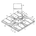
【図5】 図3の要部拡大斜視図である。
【図6】 図5のB−B線断面図である。
【図7】 隣接したパネルユニットを接合した状態における図5のB−B線断面図である。
【図8】 隣接したパネルユニットを接合した状態における図4のC−C線断面図である。
【図9】 本発明のパネルユニットを複数縦横に隣接させて構成する床暖房用パネルの第2の形態を模式的に示す平面図である。
【図10】 図9の要部の構成例を示す拡大図である。
【図11】 図10のD−D線断面図である。
【図12】 接続用部材及び供給用部材を構成する要素の一例図である。
【図13】 接続用部材を構成する他の要素の一例図である。
【図14】 供給用部材を構成する他の要素の一例図である。
【図15】 本発明のパネルユニットを複数縦横に隣接させて構成する床暖房用パネルの第3の形態を概念的に示す平面図である。
【図16】 本発明のパネルユニットを複数縦横に隣接させて構成する床暖房用パネルの第4の形態を概念的に示す平面図である。
【図17】 従来の切欠部により構成した空間部の近傍の構成の一例を示す要部平面図である。
【図18】 パネルユニットを複数縦横に隣接させて構成する床暖房用パネルの従来例を模式的に示す説明図である。
【図19】 従来の床暖房用パネルを用いて構成した床の一例を示す断面図である。
【符号の説明】
1 板状体
2(2a,2b,2c,2d) 切欠部
3 熱媒循環用パイプ
3a,3b,3c,3d 経路
4 溝
5 支持脚
6 接合板
7 低段部
8 傾斜部
9 床スラブ
10 接続用部材
11 熱媒往き管
12 熱媒還り管
13 供給用部材(ヘッダー)
14 仕上床材
15 メス部材
16 オス部材
17 筒体
18 接続筒部
19 フランジ部
20 パイプ
21 嵌入筒部
22 嵌入筒部
23 ゴムパッキン
24 フランジ部
25 メス部材
26 嵌入筒部[0001]
BACKGROUND OF THE INVENTION
The present invention relates to a floor heating panel.
[0002]
[Prior art]
Recently, it has been proposed to form a floor heating panel having a desired width by vertically adjoining a plurality of panel units provided with heat medium circulation pipes.
For example, in the specification and drawings attached to the applicant's previous application, Japanese Patent Application No. Hei 8-242855, each panel unit has four square plates a 4 as shown in FIG. A notch b is provided at the corner, a support leg c (position is indicated by ◎) is installed near the lower side of the notch b, and the heat medium circulation pipe d is meandered to form one path. This is a configuration in which both ends of the pipe for use d are positioned in a notch b at one corner. In this panel unit e, the shape of the notch b is a square shape with corners notched at right angles.
[0003]
In this configuration, when each panel unit e is adjacent to each other as a group so that each corner where both ends of the heat medium circulation pipe d are located is opposed to each other, the
Thereafter, in order to close the space portion f, as shown in FIG. 19, a flooring plate i is laminated on the upper side of the panel unit e, and a finishing floor material j such as a flooring floor is laminated on the upper side to constitute a floor. Yes.
[0004]
[Problems to be solved by the invention]
The plywood i is not laminated corresponding to only the upper side of the space part f, but is laminated on the entire upper side of the adjacent panel unit U, so that the board overlaps in the part other than the space part. There is.
For this reason, the heat transfer distance from the heat medium circulation pipe d to the upper surface of the floor becomes long, and depending on the configuration and thickness of the finished floor material j such as a flooring floor, sufficient thermal performance cannot be obtained, and the cost increases. It is also.
The present invention aims to solve such problems.
[0005]
[Means for Solving the Problems]
To solve the problems described above, with the present invention, provided the notch of right isosceles triangular in the corner portion of the positive square of the plate, constituting the low-stage portion inward from the edge of the notch, The end of the heat medium circulation pipe is arranged in a notch to form a panel unit, and a plurality of panel units are vertically and horizontally adjacent to each other to have a desired size. An inclined portion is formed in the groove on the upper surface of the plate-like body on which the pipe for heat circulation leading to this space portion is mounted, and the lower step portion formed around this space portion has the same thickness as the depth thereof. It is proposed that the adjacent panel unit is joined by fitting the joining plate and fixing the joining plate to each panel unit to form a surface having no level difference from the panel surface .
[0006]
In the present invention, the notch portion is configured in a square shape in which the corners of the plate-like body are cut out at right angles as in the prior art, and is formed in a right-angled isosceles triangle shape in which the corners of the plate-like body are cut out obliquely. Can do.
[0007]
Further, in the present invention, the notch portions can be provided only at the two adjacent corners of the plate-like body in addition to being provided at all corners of the plate-like body.
[0008]
In the present invention described above, the notches can be provided only at the two adjacent corners in addition to the configuration provided at the four corners of the plate-like body.
[ 0009 ]
According to the present invention described above, when the joining plate is fitted to the lower step portion around the space portion and fixed to each panel unit, the joining plate closes the space portion and simultaneously joins four adjacent panel units. Furthermore, since the upper surface of each panel unit and the upper surface of the joining plate can be on the same plane, the finishing floor plate can be laminated without laminating the plywood.
[ 0010 ]
DETAILED DESCRIPTION OF THE INVENTION
Next, embodiments of the present invention will be described with reference to the drawings.
First, FIG. 1 is a plan view showing an embodiment of a panel unit U to which the present invention is applied, and FIG. 2 is a sectional view taken along line AA of FIG. FIG. 3 is a plan view schematically showing a part of a floor heating panel configured by adjoining a plurality of panel units U of FIG. 1 vertically and horizontally.
As shown in FIG. 2, a plurality of
In other words, the heat
Of the four paths of the heat
The shape of the path of each heat
As long as the plate-
In addition, the
The heat medium is, for example, warm water. In this case, the heat
Furthermore, the structure which supports the
On the other hand, in this embodiment, the positions indicated by ◎ in the drawing on the lower side of the plate-
[ 0011 ]
In the above configuration, when a plurality of panel units U are arranged adjacent to each other in the vertical and horizontal directions, the shape rotated by 45 ° with respect to the shape of the panel unit U by the
[ 0012 ]
Joining between adjacent panel units U is performed by fitting a joining
In order to apply such a joining method, the
[ 0013 ]
FIG. 3 shows a first form of a floor heating panel configured by adjoining a plurality of panel units U vertically and horizontally, and this form includes four adjacent panel units U adjacent vertically and horizontally. It is the structure made into 1 group.
That is, in the case shown in FIG. 3, in the space portion S constituted by the
[ 0014 ]
The floor heating panel as described above can be supported at a predetermined height from the
And the floor can be comprised by laminating | stacking finishing
[ 0015 ]
At this time, a layer of a material having high thermal conductivity such as aluminum foil is formed between the finishing
[ 0016 ]
Next, a description will be given of another form of the floor heating panel configured by adjoining a plurality of panel units U of the present invention vertically and horizontally. FIG. 9 shows a second embodiment, which is the first form. As in the above embodiment, the four adjacent panel units U vertically and horizontally are configured as a group, but the direction of each adjacent panel unit U is different from that of FIG. The heating medium circulation supply form is different. This embodiment also has a configuration in which the adjacent panel unit U is joined by the joining
In this embodiment, each end portion of the two-path heat
Therefore, the heat
[ 0017 ]
Here, a specific example of the
In this specific example, the connecting
[ 0018 ]
Next, the
[ 0019 ]
In the above configuration, the
Further, in the heat
In addition, although illustration is abbreviate | omitted, when connecting the
With such connection, as described above as shown in FIG. 9, the
[ 0020 ]
The connecting
[ 0021 ]
Although not shown in the drawing, four adjacent panel units U vertically and horizontally are regarded as one group, and all the heat
[ 0022 ]
Next, FIG. 15 shows a third embodiment of the floor heating panel of the present invention configured by adjoining a plurality of panel units U vertically and horizontally. In this embodiment, each panel unit U has a notch at four corners. However, the path of the heat
[ 0023 ]
In this configuration, in the space portion S formed on one side of each group row, the connection with the adjacent panel unit U is performed together with the connection of each path by the bonding
[ 0024 ]
Next, FIG. 16 shows a fourth embodiment of a floor heating panel according to the present invention, which is a third embodiment except that
In this embodiment, since no space is formed in the adjacent portion where the sides of the panel unit U not provided with the
[ 0025 ]
As described above, in the panel unit U in which the plate-
[ 0026 ]
【The invention's effect】
As described above, according to the present invention, the adjacent four panel units are fitted to the lower step portion formed around the space portion formed by the facing notch portions, and the joining plate is fitted to each panel unit. Since it is fixed, the joining plate closes the space portion and joins the four adjacent panel units, and furthermore, the upper surface of each panel unit and the upper surface of the joining plate can be on the same plane. The finished floor board can be laminated without laminating.
In this way, in the present invention, since the plywood is not necessary, the heat transfer distance from the heat medium circulation pipe to the upper surface of the finishing floor board is shortened, and sufficient thermal performance can be obtained and the cost can be reduced. it can.
[Brief description of the drawings]
FIG. 1 is a plan view conceptually showing an embodiment of a panel unit to which the present invention is applied.
FIG. 2 is a cross-sectional view taken along line AA in FIG.
FIG. 3 is a plan view schematically showing a first form of a floor heating panel configured by adjoining a plurality of panel units of the present invention vertically and horizontally.
4 is an enlarged plan view of a main part of FIG. 3;
FIG. 5 is an enlarged perspective view of a main part of FIG.
6 is a cross-sectional view taken along line BB in FIG.
7 is a cross-sectional view taken along line BB of FIG. 5 in a state where adjacent panel units are joined.
8 is a cross-sectional view taken along line CC of FIG. 4 in a state where adjacent panel units are joined.
FIG. 9 is a plan view schematically showing a second form of a floor heating panel configured by adjoining a plurality of panel units of the present invention vertically and horizontally.
10 is an enlarged view showing a configuration example of a main part of FIG. 9;
11 is a cross-sectional view taken along the line DD of FIG.
FIG. 12 is an example diagram of elements constituting a connection member and a supply member.
FIG. 13 is an example of another element constituting the connection member.
FIG. 14 is an example of another element constituting the supply member.
FIG. 15 is a plan view conceptually showing a third embodiment of a floor heating panel configured by adjoining a plurality of panel units of the present invention vertically and horizontally.
FIG. 16 is a plan view conceptually showing a fourth embodiment of a floor heating panel configured by adjoining a plurality of panel units of the present invention vertically and horizontally.
FIG. 17 is a plan view of an essential part showing an example of a configuration in the vicinity of a space formed by a conventional notch.
FIG. 18 is an explanatory view schematically showing a conventional example of a floor heating panel configured by adjoining a plurality of panel units vertically and horizontally.
FIG. 19 is a cross-sectional view showing an example of a floor configured using a conventional floor heating panel.
[Explanation of symbols]
DESCRIPTION OF
14
Claims (4)
Priority Applications (1)
| Application Number | Priority Date | Filing Date | Title |
|---|---|---|---|
| JP07538697A JP3666773B2 (en) | 1997-03-27 | 1997-03-27 | Floor heating panel |
Applications Claiming Priority (1)
| Application Number | Priority Date | Filing Date | Title |
|---|---|---|---|
| JP07538697A JP3666773B2 (en) | 1997-03-27 | 1997-03-27 | Floor heating panel |
Publications (2)
| Publication Number | Publication Date |
|---|---|
| JPH10267303A JPH10267303A (en) | 1998-10-09 |
| JP3666773B2 true JP3666773B2 (en) | 2005-06-29 |
Family
ID=13574714
Family Applications (1)
| Application Number | Title | Priority Date | Filing Date |
|---|---|---|---|
| JP07538697A Expired - Fee Related JP3666773B2 (en) | 1997-03-27 | 1997-03-27 | Floor heating panel |
Country Status (1)
| Country | Link |
|---|---|
| JP (1) | JP3666773B2 (en) |
Cited By (1)
| Publication number | Priority date | Publication date | Assignee | Title |
|---|---|---|---|---|
| CN102331022A (en) * | 2011-09-29 | 2012-01-25 | 无锡职业技术学院 | Novel floor heating pipeline |
Families Citing this family (1)
| Publication number | Priority date | Publication date | Assignee | Title |
|---|---|---|---|---|
| JP5685982B2 (en) * | 2011-02-23 | 2015-03-18 | 三菱樹脂株式会社 | Floor heating piping connection structure |
-
1997
- 1997-03-27 JP JP07538697A patent/JP3666773B2/en not_active Expired - Fee Related
Cited By (1)
| Publication number | Priority date | Publication date | Assignee | Title |
|---|---|---|---|---|
| CN102331022A (en) * | 2011-09-29 | 2012-01-25 | 无锡职业技术学院 | Novel floor heating pipeline |
Also Published As
| Publication number | Publication date |
|---|---|
| JPH10267303A (en) | 1998-10-09 |
Similar Documents
| Publication | Publication Date | Title |
|---|---|---|
| US20090314848A1 (en) | Radiant Heating System and Method | |
| JP3666773B2 (en) | Floor heating panel | |
| JP3808697B2 (en) | Heating panel assembly and method for folding heating panel assembly | |
| JP5125292B2 (en) | Hot water panel for floor heating | |
| JP3630259B2 (en) | Floor heating panel | |
| JP3603983B2 (en) | Floor heating panel unit and floor heating panel using the same | |
| JPH10267302A (en) | Panel for floor heater | |
| JP3755703B2 (en) | Floor heating panel | |
| JP3678491B2 (en) | Room temperature adjuster | |
| JP3808196B2 (en) | Fixing method of discarded plywood in floor heating panels | |
| JPH10253086A (en) | Floor heating panel | |
| JPH10246451A (en) | Panel unit for floor heating and panel for floor heating using the same | |
| JPH10253084A (en) | Floor heating panel | |
| JPH11190530A (en) | Panel for floor heating | |
| JPH10267300A (en) | Panel unit for floor heating and panel for floor heating, which employs the same | |
| JP5181577B2 (en) | Groove structure for water pipe arrangement in hot water mat for floor heating | |
| JP3798315B2 (en) | Floor heating system | |
| JP6836870B2 (en) | Floor heating panel and floor heating panel structure | |
| JP4319441B2 (en) | Fluid branch fixture | |
| JP3808708B2 (en) | Connecting pipe guide panel and floor heating panel | |
| JP2000111068A (en) | Hot water mat for hot water type floor heating system and mat material | |
| JPH11173578A (en) | Floor heating panel unit and floor heating panel using it | |
| JP3182126B2 (en) | Floor heated building floor structure | |
| JP3919080B2 (en) | Base panel for heat sink | |
| JP2009063248A (en) | Warm water mat for floor heating |
Legal Events
| Date | Code | Title | Description |
|---|---|---|---|
| A977 | Report on retrieval |
Free format text: JAPANESE INTERMEDIATE CODE: A971007 Effective date: 20041220 |
|
| A131 | Notification of reasons for refusal |
Free format text: JAPANESE INTERMEDIATE CODE: A131 Effective date: 20050105 |
|
| A521 | Written amendment |
Free format text: JAPANESE INTERMEDIATE CODE: A523 Effective date: 20050225 |
|
| TRDD | Decision of grant or rejection written | ||
| A01 | Written decision to grant a patent or to grant a registration (utility model) |
Free format text: JAPANESE INTERMEDIATE CODE: A01 Effective date: 20050330 |
|
| A61 | First payment of annual fees (during grant procedure) |
Free format text: JAPANESE INTERMEDIATE CODE: A61 Effective date: 20050401 |
|
| R150 | Certificate of patent or registration of utility model |
Free format text: JAPANESE INTERMEDIATE CODE: R150 |
|
| FPAY | Renewal fee payment (event date is renewal date of database) |
Free format text: PAYMENT UNTIL: 20090415 Year of fee payment: 4 |
|
| FPAY | Renewal fee payment (event date is renewal date of database) |
Free format text: PAYMENT UNTIL: 20090415 Year of fee payment: 4 |
|
| FPAY | Renewal fee payment (event date is renewal date of database) |
Free format text: PAYMENT UNTIL: 20100415 Year of fee payment: 5 |
|
| FPAY | Renewal fee payment (event date is renewal date of database) |
Free format text: PAYMENT UNTIL: 20110415 Year of fee payment: 6 |
|
| LAPS | Cancellation because of no payment of annual fees |