JP3666519B2 - Contact switching device for battery compartment - Google Patents
Contact switching device for battery compartment Download PDFInfo
- Publication number
- JP3666519B2 JP3666519B2 JP24065595A JP24065595A JP3666519B2 JP 3666519 B2 JP3666519 B2 JP 3666519B2 JP 24065595 A JP24065595 A JP 24065595A JP 24065595 A JP24065595 A JP 24065595A JP 3666519 B2 JP3666519 B2 JP 3666519B2
- Authority
- JP
- Japan
- Prior art keywords
- battery
- terminal plate
- batteries
- contact
- switching device
- Prior art date
- Legal status (The legal status is an assumption and is not a legal conclusion. Google has not performed a legal analysis and makes no representation as to the accuracy of the status listed.)
- Expired - Fee Related
Links
Images


Classifications
-
- Y—GENERAL TAGGING OF NEW TECHNOLOGICAL DEVELOPMENTS; GENERAL TAGGING OF CROSS-SECTIONAL TECHNOLOGIES SPANNING OVER SEVERAL SECTIONS OF THE IPC; TECHNICAL SUBJECTS COVERED BY FORMER USPC CROSS-REFERENCE ART COLLECTIONS [XRACs] AND DIGESTS
- Y02—TECHNOLOGIES OR APPLICATIONS FOR MITIGATION OR ADAPTATION AGAINST CLIMATE CHANGE
- Y02E—REDUCTION OF GREENHOUSE GAS [GHG] EMISSIONS, RELATED TO ENERGY GENERATION, TRANSMISSION OR DISTRIBUTION
- Y02E60/00—Enabling technologies; Technologies with a potential or indirect contribution to GHG emissions mitigation
- Y02E60/10—Energy storage using batteries
Description
【0001】
【発明の属する技術分野】
本発明は電池収納部の接点切換え装置に係り、とくに2種類の電池を選択的に収納することができる電池収納部の接点切換え装置に関する。
【0002】
【従来の技術】
例えばポータブル型のテープレコーダの電源として、従来よりニッケルカドミニウム電池等から成る2次電池が用いられている。このような2次電池は充電器によって商用電源で充電することができるために、繰返して使用することができる。また何回も繰返して使用することができることから、使用済みの電池の廃棄の問題を生ずることが少ない。
【0003】
【発明が解決しようとする課題】
このようにポータブル型電子機器をニッケルカドミニウム電池等の2次電池によって駆動する場合には、この2次電池が放電した場合には充電を行なわなければならず、その間は電子機器を使用することができない。すなわち乾電池から成る1次電池のように、店頭で販売されている新しい電池を買って使用することができない。
【0004】
そこでニッケルカドミニウム電池等の2次電池を使用することができるようにするとともに、乾電池の使用をも可能にしたポータブル型の電子機器が提案されている。ところがニッケルカドミニウム電池と乾電池とでは、その外側の形状および寸法が異なっているために、このように2種類の電池を使用する場合には、それぞれの電池を別々に収納するための電池収納部を設けなければならない。従ってキャビネット内にこれら2種類の電池を収納する電池収納部を設けなければならず、これによってスペースファクタが悪化し、電子機器の小型化が妨げられることになる。
【0005】
同一個所に2種類の電池を収納する電池収納部を設けるようにした電気製品が存在するが、この場合には手動によって仕切り板等の区画壁の位置を変更し、電池ボックスのサイズを切換えるようにしている。従って異なる種類の電池を入れる場合には、上記のような仕切板を移動させなければならず、その操作が面倒になるばかりか、この操作を知らないと何種類かの電池を切換えて使用することができなくなる。
【0006】
本発明はこのような問題点に鑑みてなされたものであって、共通の電池収納部によって2種類の電池を収納して選択的に使用することができるようにした電池収納部の接点切換え装置を提供することを目的とするものである。
【0007】
【課題を解決するための手段】
本発明は、2種類の電池を選択的に収納することができる電池収納部の一端に第1の端子板とともに移動可能に第2の端子板を設けるようにし、第1の電池を収納するとこの電池が第2の端子板に設けられている当接部と当接し、これによって第2の端子板が第1の電池の装着を阻害しない位置へ移動するようにし、電池収納部の蓋の内側に上記第1の端子板および第2の端子板とは反対側の極性の端子板を設けるようにし、この端子板を電池収納部に収納される2種類の電池に共通に使用するようにしたものである。
【0008】
上記当接部は第2の端子板に設けられている深絞りの突部から構成されてよい。
【0010】
このような電池収納部に選択的に収納される2種類の電池の内の一方が角型の2次電池から構成されるとともに、他方が円柱状の1次電池から構成されてよい。
【0011】
電池収納部の一端に移動可能に設けられている第2の端子板には円柱状の1次電池のマイナス側の電極と接触するコイルばねが取付けられてよい。
【0012】
【発明の実施の形態】
図1は本発明の一実施の形態に係る電池収納部の接点切換え装置を有するポータブル型テープレコーダのワイヤレスのリモートコントローラを示すものであって、このリモートコントローラは合成樹脂成形体から成るシャーシ10を備えている。このシャーシ10の一方の側面側にはフロントキャビネット11が接合されるとともに、他方の側面にはリヤキャビネット12が接合されるようになっており、シャーシ10とフロントキャビネット11とリヤキャビネット12とによってリモートコントローラのキャビネットが組立てられるようになっている。なおリヤキャビネット12内にはイヤホンコードを巻取るリールが内蔵されている。
【0013】
シャーシ10上にはプリント基板保持部13が設けられており、このプリント基板保持部13内に異形の扇形をなすブリント基板14が収納されている。プリント基板14上には各種の電子部品15やIC16、ボリュームつまみ17等がマウントされ、これらが配線パターンによって互いに接続され所定の回路を形成しており、このような電子回路によってワイヤレスのリモートコントローラが構成されている。
【0014】
シャーシ10のプリント基板保持部13の反対側には電池収納部18が設けられている。電池収納部18は角型をなす2次電池の側面を受ける段部19と、円柱状をなす1次電池の側面を受ける円弧状保持部20をそれぞれ備え、このような形状によって2種類の電池を選択的に収納することができるようにしている。またこの電池収納部18の一端の開口が電池蓋21によって閉じられるようになっている。
【0015】
次に上記電池収納部18の奥側の一端に設けられている第1の端子板25と第2の端子板34の構成について説明する。図2〜図4に示すように、第1の端子板25は電池収納部18の奥の部分に固定配置されるようになっており、その一端に設けられている接続部26がプリント基板14の下側から上面に挿通されるようになっており、この接続部26がプリント基板14上の配線パターンに半田付けして接続されるようになっている。そして端子板25の下端側は折曲げ片27から構成されるとともに、この折曲げ片27の先端部に形成されている突部28が端子を構成するようになっている。
【0016】
これに対してプリント基板14の側端側には連結板31が固定されるとともに、この連結板31の下端側はヒンジを構成する保持筒32を備えており、この保持筒32内に挿通されるヒンジピン33によって第2の端子板34の端部が回動可能に支持されている。
【0017】
第2の端子板34は上方に突出するように深絞りの突部35を備えるとともに、この突部35よりも先端側の側部に端板36を備え、この端板36には端子を構成するコイルばね37が固着されている。また第2の端子板34の下面にはコイルばねから成る押圧ばね38が配されている。図1に示すようにこの押圧ばね38はフロントキャビネット11の内側の所定の位置に固定されている。
【0018】
次に反対側の端子板の構造について説明すると、図1に示すようにプリント基板14の反対側の端部にはピン41が直立するように植設されており、このピン41がプラス側の端子板42を回転自在に支持している。ブラス側端子板42は上記電池蓋21の内側に設けられている保持用リブ43、44によって上下の縁部が挟着保持されるようになっている。従ってピン41が電池蓋21のヒンジを構成することになる。
【0019】
次に以上のような構成になる電池収納部への電池の収納動作について説明する。ここでは角型であってニッケルカドミニウム電池から成るガム型2次電池47と円柱状1次電池48とが選択的に用いられるようになっている。
【0020】
ガム型2次電池47は図4〜図6に示すようにしてこの電池収納部18に収納保持されるようになっている。
【0021】
電池収納部18にガム型2次電池47を収納する場合には、電池収納部18の一端の開口を覆っている電池蓋21をプラス側端子板42とともに開放する。そしてこの電池収納部18の段部19に側面が接触するようにガム型2次電池47を挿入する。するとこの2次電池47のマイナス側の電極は図4〜図6に示すように、電池収納部18の奥の部分に設けられている第2の端子板34の深絞りの突部35に接触し、これによって端子板34が押圧ばね38に抗して図3および図4に示すようにヒンジピン33を中心として反時計方向に回動される。すなわちガム型2次電池47を挿入すると、その先端側の部分によって第2の端子板34の突部35が押されてこの2次電池47の装着を阻害しないように下方へ移動することになる。
【0022】
従ってガム型2次電池47をさらに電池収納部18内に押込むと、その先端側であってマイナス側の電極が電池収納部18の奥の部分に設けられている第1の端子板25の折曲げ片27の突部28に当接することになる。このような状態において電池蓋21を閉じると、この電池蓋21の内側のリブ43、44によって保持されているプラス側端子板42がガム型2次電池47のプラス側の電極と図5および図6に示すように接触することになる。従ってプラス側の端子板42およびマイナス側の第1の端子板25を通してこのガム型2次電池47の出力を取出すことが可能になる。
【0023】
次に1次電池、例えば円柱状をなす単4の乾電池を使用する場合には、図7および図8に示すように、電池収納部18内に円柱状1次電池48を挿入する。1次電池48はその半径方向の寸法がガム型2次電池47の同方向の寸法よりも小さく、電池収納部18の奥の部分に設けられている第1の端子板25の切欠き50によって案内された状態でそのまま電池収納部18に収納されるとともに、円弧状保持部20によって保持される。
【0024】
すなわちこの場合には、第1の端子板25は押圧ばね38によって図8に示すように上方へ回動した位置のままで円柱状1次電池48の挿入が行なわれる。そしてこのような1次電池48のマイナス側の電極は第2の端子板34の端板36に設けられているコイルばね37を変形させながらこのコイルばね37と接触することになる。
【0025】
従ってこのような状態で電池蓋21を閉じると、この1次電池48のプラス側の電極がプラス側端子板42に接触することになる。よってプラス側端子板42と第2の端子板34のコイルばね37とによって円柱状1次電池48の出力を取出すことが可能になる。
【0026】
このように本実施の形態によれば、円柱状をなす1次電池48を図7および図8に示すように挿入すると、この円柱状1次電池48に専用のマイナス側の端子板34のコイルばね37と1次電池48のマイナス側の電極とが接触する。このときに端子板34は押圧ばね38で下方から上方に押されている。またこの1次電池48は端子板34の深絞りの突部35には接触しないために、端子板34が回動することがない。
【0027】
これに対して図4に示すようにニッケルカドミニウム電池から成るガム型2次電池47を挿入すると、第2の端子板34の深絞りの突部35のテーパ部に2次電池47の先端部が当り、これによって端子板34が図4に示すように下方へ回動することになり、この端子板34と2次電池47との干渉が避けられる。従ってこの2次電池47のマイナス側の電極が第1の端子板25の折曲げ片27に形成されている端子28に接触して導通することになる。なおこのガム型2次電池47を取外すと、押圧ばね38の弾性復元力によって第2の端子板34は図3に示す状態から図2に示す状態に復帰することになる。
【0028】
すなわち本実施の形態は、大きさおよび長さの異なる2種類の電池47、48の違いを利用し、これらの電池47、48の挿入時に自動的にマイナス側の端子を切換えるようにしており、手動で切換えたり特別な部品を使用したものではない。
【0029】
ガム型2次電池47の挿入時には、円柱状1次電池48に専用の回動式の第2の端子板34がその深絞りのテーパ部35によって逃げるようにし、これによってガム型2次電池47が円柱状1次電池48に専用のマイナス側の第2の端子板34と接触することがなく、ガム型2次電池専用の第1の端子板25の折曲げ片27の突部28と接触して導通をとるようにしたものである。
【0030】
このような構成によれば、電池収納部18にガム型2次電池47または円柱状1次電池48を挿入した場合に、それらの電池の形状の差異を利用して自動的にマイナス側の端子板25、34の切換えが行なわれるために、操作性が良好である。また電池収納部18の形状に若干の工夫をこらすものの、この電池収納部18の大部分の空間はガム型2次電池47と円柱状1次電池48とに共通に用いられるために、別々の電池収納部を設ける場合に比べてはるかにスペース効率がよく、これによってキャビネットの大型化が防止される。また2種類の電池に専用の電池収納部をそれぞれ別々に設けるようにしている場合に比べて、コストの増大を最小限に抑えることが可能になる。
【0031】
【発明の効果】
以上のように本発明は、2種類の電池を選択的に収納することができる電池収納部の一端に第1の端子板とともに移動可能に第2の端子板を設けるようにし、第1の電池を収納するとこの第1の電池が第2の端子板に設けられている当接部と当接し、これによって第2の端子板が第1の電池の装着を阻害しない位置へ移動するようにし、電池収納部の蓋の内側に第1の端子板および第2の端子板とは反対側の極性の端子板を設けるようにし、2種類の電池に共通に使用するようにしたものである。
【0032】
従って電池の収納によって第1の端子板と第2の端子板との自動切換えを行なうことが可能になり、操作性に優れるとともに、共通の電池収納部を用いて2種類の電池を選択的に収納することができ、スペース効率が改善されることになる。しかも電池収納部の蓋の内側に第1の端子板および第2の端子板とは反対側の極性の端子板を設けるようにし、2種類の電池に共通に使用することによって、反対側の極性の端子板を単一の端子板から構成することが可能になる。
【0033】
当接部を第2の端子板に設けられている深絞りの突部から構成すると、この深絞りの突部に第1の電池が当接することによって第2の端子板を第1の電池の装着を阻害しない位置へ移動させることが可能になる。
【0035】
2種類の電池の内の一方が角型の2次電池から構成されるとともに、他方が円柱状の1次電池から構成されることによって、これらの2種類の電池を選択的に電池収納部に収納してその出力を取出すことが可能になる。
【0036】
第2の端子板に円柱状の1次電池のマイナス側の電極と接触するコイルばねを取付けるようにした構成によれば、円柱状の1次電池を用いた場合にはこのコイルばねを通して円柱状の1次電池の出力が取出されるようになる。
【図面の簡単な説明】
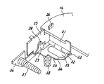
【図1】一実施の形態に係る電池収納部の接点切換え装置を有するワイヤレスのリモートコントローラの分解斜視図である。
【図2】同電池収納部に設けられているマイナス側の端子板の構造を示す要部斜視図である。
【図3】第2の端子板を回動させた状態のの斜視図である。
【図4】ガム型2次電池を挿入した状態の正面図である。
【図5】同側面図である。
【図6】同平面図である。
【図7】円柱状1次電池を挿入した状態の要部斜視図である。
【図8】同要部正面図である。
【符号の説明】
10 シャーシ
11 フロントキャビネット
12 リヤキャビネット
13 プリント基板保持部
14 プリント基板
15 部品
16 IC
17 ボリュームつまみ
18 電池収納部
19 段部
20 円弧状保持部
21 電池蓋
25 第1の端子板
26 接続部
27 折曲げ片
28 突部(端子)
31 連結板
32 保持筒
33 ヒンジピン
34 第2の端子板
35 突部
36 端板
37 コイルばね(端子)
38 押圧ばね(コイルばね)
41 ピン
42 プラス側端子板
43、44 保持用リブ
47 ガム型2次電池
48 円柱状1次電池
50 切欠き[0001]
BACKGROUND OF THE INVENTION
The present invention relates to a contact switching device for a battery storage unit, and more particularly to a contact switching device for a battery storage unit capable of selectively storing two types of batteries.
[0002]
[Prior art]
For example, as a power source for a portable tape recorder, a secondary battery made of a nickel cadmium battery or the like has been conventionally used. Since such a secondary battery can be charged with a commercial power source by a charger, it can be used repeatedly. Further, since it can be used repeatedly many times, there is little problem of disposal of used batteries.
[0003]
[Problems to be solved by the invention]
Thus, when a portable electronic device is driven by a secondary battery such as a nickel cadmium battery, the secondary battery must be charged when it is discharged, and the electronic device can be used during that time. Can not. That is, it is not possible to buy and use a new battery sold at a store like a primary battery made of a dry battery.
[0004]
In view of this, there has been proposed a portable electronic device that can use a secondary battery such as a nickel cadmium battery and can also use a dry battery. However, since nickel cadmium batteries and dry batteries have different shapes and dimensions on the outside, when two types of batteries are used in this way, a battery storage section for storing each battery separately is provided. Must be provided. Therefore, it is necessary to provide a battery storage section for storing these two types of batteries in the cabinet, which deteriorates the space factor and prevents downsizing of the electronic device.
[0005]
There is an electric product that has a battery storage part for storing two types of batteries at the same location. In this case, the position of the partition wall such as a partition plate is manually changed to change the size of the battery box. I have to. Therefore, when inserting different types of batteries, the partition plate as described above must be moved, which not only makes the operation cumbersome, but also switches several types of batteries without knowing this operation. I can't do that.
[0006]
The present invention has been made in view of such a problem, and a contact switching device for a battery storage unit that can be used selectively by storing two types of batteries by a common battery storage unit. Is intended to provide.
[0007]
[Means for Solving the Problems]
According to the present invention, a second terminal plate is provided at one end of a battery storage portion capable of selectively storing two types of batteries so as to be movable together with the first terminal plate. battery provided abutting portion abuts and a second terminal plate, thereby as the second terminal plate is moved to a position that does not inhibit the attachment of the first battery, the inside of the lid of the battery compartment A terminal plate having a polarity opposite to that of the first terminal plate and the second terminal plate is provided, and this terminal plate is commonly used for two types of batteries stored in the battery storage portion . Is.
[0008]
The abutting portion may be formed of a deep drawing protrusion provided on the second terminal plate.
[0010]
One of the two types of batteries selectively stored in the battery storage unit may be a square secondary battery, and the other may be a cylindrical primary battery.
[0011]
A coil spring that contacts the negative electrode of the columnar primary battery may be attached to the second terminal plate that is movably provided at one end of the battery housing.
[0012]
DETAILED DESCRIPTION OF THE INVENTION
FIG. 1 shows a wireless remote controller of a portable tape recorder having a contact switching device for a battery storage unit according to an embodiment of the present invention. The remote controller includes a
[0013]
A printed circuit
[0014]
A
[0015]
Next, the configuration of the
[0016]
On the other hand, a connecting
[0017]
The second
[0018]
Next, the structure of the terminal plate on the opposite side will be described. As shown in FIG. 1, a
[0019]
Next, the operation of storing the battery in the battery storage unit configured as described above will be described. Here, a rectangular
[0020]
The gum type
[0021]
When the gum-type
[0022]
Therefore, when the gum-type
[0023]
Next, in the case of using a primary battery, for example, a AAA dry battery having a cylindrical shape, a cylindrical
[0024]
That is, in this case, the columnar
[0025]
Accordingly, when the
[0026]
Thus, according to the present embodiment, when the cylindrical
[0027]
On the other hand, as shown in FIG. 4, when a gum type
[0028]
That is, this embodiment utilizes the difference between two types of
[0029]
When the gum-type
[0030]
According to such a configuration, when the gum-type
[0031]
【The invention's effect】
As described above, according to the present invention, the second terminal plate is provided so as to be movable together with the first terminal plate at one end of the battery storage unit capable of selectively storing two types of batteries. The first battery comes into contact with the contact portion provided on the second terminal plate, so that the second terminal plate moves to a position that does not hinder the mounting of the first battery , A terminal plate having a polarity opposite to the first terminal plate and the second terminal plate is provided on the inner side of the lid of the battery housing portion, and is used in common for two types of batteries .
[0032]
Therefore, it is possible to automatically switch between the first terminal board and the second terminal board by storing the battery, and the operability is excellent, and two types of batteries are selectively used by using a common battery storage section. It can be stored, and space efficiency is improved. In addition, a terminal plate having a polarity opposite to the first terminal plate and the second terminal plate is provided on the inner side of the lid of the battery housing part, and the polarity on the opposite side is obtained by using the two types of batteries in common. It is possible to configure the terminal plate from a single terminal plate.
[0033]
If the abutting portion is constituted by a deep drawing projection provided on the second terminal plate, the second battery is brought into contact with the first battery by the first battery coming into contact with the deep drawing projection. It is possible to move to a position that does not impede mounting.
[0035]
One of the two types of batteries is composed of a square-shaped secondary battery, and the other is composed of a cylindrical primary battery. It is possible to store and take out the output.
[0036]
According to the configuration in which the coil spring that contacts the negative electrode of the cylindrical primary battery is attached to the second terminal plate, when the cylindrical primary battery is used, the cylindrical shape is passed through the coil spring. The output of the primary battery is taken out.
[Brief description of the drawings]
FIG. 1 is an exploded perspective view of a wireless remote controller having a contact switching device for a battery storage unit according to an embodiment.
FIG. 2 is a perspective view of a main part showing a structure of a minus side terminal plate provided in the battery housing part;
FIG. 3 is a perspective view of a state where a second terminal plate is rotated.
FIG. 4 is a front view of a state in which a gum type secondary battery is inserted.
FIG. 5 is a side view of the same.
FIG. 6 is a plan view of the same.
FIG. 7 is a perspective view of a main part in a state where a cylindrical primary battery is inserted.
FIG. 8 is a front view of the relevant part.
[Explanation of symbols]
DESCRIPTION OF
17
31 connecting
38 Pressing spring (coil spring)
41
Claims (4)
前記電池収納部の一端に設けられている第1の端子板と、
前記電池収納部の一端に移動可能に設けられている第2の端子板と、
前記第2の端子板に設けられており、第1の電池を収納すると該第1の電池と当接して前記第2の端子板を該第1の電池の装着を阻害しない位置へ移動させる当接部と、
を具備し、
前記電池収納部の蓋の内側に前記第1の端子板および第2の端子板とは反対側の極性の端子板が設けられ、2種類の電池に共通に使用されることを特徴とする電池収納部の接点切換え装置。A battery storage section capable of selectively storing two types of batteries;
A first terminal plate provided at one end of the battery housing;
A second terminal plate movably provided at one end of the battery housing;
The second terminal plate is provided on the second terminal plate. When the first battery is accommodated, the second terminal plate is brought into contact with the first battery and moved to a position that does not obstruct the mounting of the first battery. The tangent,
Equipped with,
A battery having a polarity opposite to the first terminal board and the second terminal board is provided inside a lid of the battery housing portion, and is used in common for two types of batteries. Contact switching device for storage.
Priority Applications (1)
| Application Number | Priority Date | Filing Date | Title |
|---|---|---|---|
| JP24065595A JP3666519B2 (en) | 1995-08-25 | 1995-08-25 | Contact switching device for battery compartment |
Applications Claiming Priority (1)
| Application Number | Priority Date | Filing Date | Title |
|---|---|---|---|
| JP24065595A JP3666519B2 (en) | 1995-08-25 | 1995-08-25 | Contact switching device for battery compartment |
Publications (2)
| Publication Number | Publication Date |
|---|---|
| JPH0963556A JPH0963556A (en) | 1997-03-07 |
| JP3666519B2 true JP3666519B2 (en) | 2005-06-29 |
Family
ID=17062728
Family Applications (1)
| Application Number | Title | Priority Date | Filing Date |
|---|---|---|---|
| JP24065595A Expired - Fee Related JP3666519B2 (en) | 1995-08-25 | 1995-08-25 | Contact switching device for battery compartment |
Country Status (1)
| Country | Link |
|---|---|
| JP (1) | JP3666519B2 (en) |
Families Citing this family (1)
| Publication number | Priority date | Publication date | Assignee | Title |
|---|---|---|---|---|
| JP5329791B2 (en) * | 2007-10-24 | 2013-10-30 | 株式会社東芝 | Wireless information input device, wireless device, and electronic device |
-
1995
- 1995-08-25 JP JP24065595A patent/JP3666519B2/en not_active Expired - Fee Related
Also Published As
| Publication number | Publication date |
|---|---|
| JPH0963556A (en) | 1997-03-07 |
Similar Documents
| Publication | Publication Date | Title |
|---|---|---|
| US4064447A (en) | Cordless portable electrically powered device | |
| US5157318A (en) | Structure of battery charger for different size and specification batteries | |
| US4086523A (en) | Rechargeable battery | |
| US5713749A (en) | Multi-functional charging device | |
| US4083011A (en) | Battery holder and connector for a radio receiver or the like | |
| GB2260040A (en) | Battery charger | |
| CA2565372A1 (en) | A battery charger for charging different types of battery pack | |
| JP3666519B2 (en) | Contact switching device for battery compartment | |
| JP3269048B2 (en) | Battery pack and power supply device equipped with the battery pack | |
| JP2006252825A (en) | Electronic apparatus | |
| JP4118408B2 (en) | Charging system, charger, electronic device and battery pack | |
| JP3560785B2 (en) | Battery storage device | |
| JPS58152231A (en) | Camera capable of using dissimilar battery | |
| JP3576035B2 (en) | Battery storage structure | |
| JP4036763B2 (en) | Electric equipment having a power plug and a power inlet | |
| JP4010028B2 (en) | Charger | |
| JPH0745879Y2 (en) | Battery pack spacer | |
| JPH0745880Y2 (en) | Battery storage device | |
| JP2001243932A (en) | Battery cover device | |
| JP2002208386A (en) | Portable electronic equipment | |
| JP2554142Y2 (en) | Charger for small electrical equipment | |
| JPH0689744A (en) | Communication device and charging device for it and rechargeable battery | |
| JP3375201B2 (en) | Battery holder for electronic and electrical equipment | |
| JPS6281938A (en) | Power source for electronic device | |
| JPH017975Y2 (en) |
Legal Events
| Date | Code | Title | Description |
|---|---|---|---|
| A977 | Report on retrieval |
Free format text: JAPANESE INTERMEDIATE CODE: A971007 Effective date: 20041129 |
|
| A131 | Notification of reasons for refusal |
Free format text: JAPANESE INTERMEDIATE CODE: A131 Effective date: 20041222 |
|
| A521 | Written amendment |
Free format text: JAPANESE INTERMEDIATE CODE: A523 Effective date: 20050221 |
|
| TRDD | Decision of grant or rejection written | ||
| A01 | Written decision to grant a patent or to grant a registration (utility model) |
Free format text: JAPANESE INTERMEDIATE CODE: A01 Effective date: 20050316 |
|
| A61 | First payment of annual fees (during grant procedure) |
Free format text: JAPANESE INTERMEDIATE CODE: A61 Effective date: 20050329 |
|
| FPAY | Renewal fee payment (event date is renewal date of database) |
Free format text: PAYMENT UNTIL: 20080415 Year of fee payment: 3 |
|
| FPAY | Renewal fee payment (event date is renewal date of database) |
Free format text: PAYMENT UNTIL: 20090415 Year of fee payment: 4 |
|
| FPAY | Renewal fee payment (event date is renewal date of database) |
Free format text: PAYMENT UNTIL: 20090415 Year of fee payment: 4 |
|
| FPAY | Renewal fee payment (event date is renewal date of database) |
Free format text: PAYMENT UNTIL: 20100415 Year of fee payment: 5 |
|
| LAPS | Cancellation because of no payment of annual fees |