JP3666412B2 - Communications system - Google Patents
Communications system Download PDFInfo
- Publication number
- JP3666412B2 JP3666412B2 JP2001140548A JP2001140548A JP3666412B2 JP 3666412 B2 JP3666412 B2 JP 3666412B2 JP 2001140548 A JP2001140548 A JP 2001140548A JP 2001140548 A JP2001140548 A JP 2001140548A JP 3666412 B2 JP3666412 B2 JP 3666412B2
- Authority
- JP
- Japan
- Prior art keywords
- signal
- network connection
- response
- incoming call
- control device
- Prior art date
- Legal status (The legal status is an assumption and is not a legal conclusion. Google has not performed a legal analysis and makes no representation as to the accuracy of the status listed.)
- Expired - Lifetime
Links
Images


Description
【0001】
【発明の属する技術分野】
本発明はネットワークを使って通話を行う通話システム等の通信システムに係わり、特にネットワークに接続され呼制御の信号をネットワークに送出する各種装置の障害を検出できるようにした通信システムに関する。
【0002】
【従来の技術】
インターネット等のネットワークでIPプロトコル(Internet Protocol)を使用して音声データをパケットで送受信する技術が注目されている。このVoIP(Voice over Internet Protocol)という技術を使用すると、たとえば地理的に離れた本店と各支店間の通話をインターネットによる常時接続サービスあるいは専用線を利用して安価な通信システムに構築することができる。
【0003】
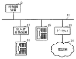
図8は、従来のこのような通信システムの要部を表わしたものである。LAN(ローカルエリアネットワーク)11には、VoIPによる呼制御を行う呼制御装置12が接続されている。また、ゲートウェイ13を介して一般の電話網14が接続されている。ゲートウェイ13は、既存の電話網14における呼制御プロトコルとLAN11上における呼制御プロトコルの変換を行うようになっている。LAN11上にはVoIP対応の電話機(以下、VoIP電話機と称す。)15が接続されている。また、既存の電話機(以下、既存電話機と称する。)16は加入者変換装置17を介してLAN11に接続されている。加入者変換装置17は、既存電話機16における呼制御プロトコルとLAN11上における呼制御プロトコルの変換を行うようになっている。
【0004】
このような従来の通信システムで、呼制御装置12、ゲートウェイ13、VoIP電話機15および加入者変換装置17はLAN11に直接接続されている。このようにLAN11に接続されている装置を本明細書ではネットワーク接続装置と総称することにする。通話システムで、このようなネットワーク接続装置に障害が発生したり、これらのネットワーク接続装置がLAN11から切り離されてしまうと、これに関係した電話機で通話を行うことができなくなる。たとえば、呼制御装置12やゲートウェイ13にこのような異常が発生すれば、電話網14を介して図示しない他の電話機との通話ができなくなる。また、加入者変換装置17やVoIP電話機15に異常が発生すれば、これらの間で通話ができなくなったり、これらのいずれかと電話網14を介して図示しない他の電話機との間でVoIPを用いた通話を行うことができなくなる。
【0005】
そこで、従来からLAN11に接続されたこれらネットワーク接続装置間では、定期的に異常の有無をチェックするための制御信号を送受信することが行われていた。そして、これらの制御信号にそれぞれのネットワーク接続装置が応答を返すことで、ネットワーク接続装置同士が正常であることを確認するようになっていた。このような技術は、たとえば特開平2−87855号公報に開示されている。
【0006】
【発明が解決しようとする課題】
各ネットワーク接続装置の異常の有無を判別する制御信号は、音声を伝送するパケットと共にそれぞれのネットワーク接続装置間で同一のLAN11上をパケット信号として伝送されることになる。この異常の有無を判別する制御信号は純粋な呼制御のための信号とは別のものであり、またLAN11上にネットワーク接続装置が多く接続されていれば、それに応じて数多くの信号が定期的に送受信されることになる。これは、LAN11を流れる信号のトラヒックの増大を招き、好ましいことではない。また、IPパケットの送受信に際してはIPプロトコル処理を行う必要がある。したがって、異常の有無を判別するための信号の増加はそれぞれのネットワーク接続装置にかなりの負荷を生じさせることになる。
【0007】
そこで、特開平6−30116号公報では、システムの主装置に電源が投入された時点で診断タスクを実行するようにしている。この診断タスクではシステムを構成する各部(ネットワーク接続装置)を起動して診断を行い、これらの結果を一箇所の記憶部に書き込み、更にタイマを起動してタイム・アウトが発生するたびに診断を行う。
【0008】
特開平6−30116号公報で開示されたこのような技術では、各部の診断を特別に割り当てられた時間で行う点で各ネットワーク接続装置の負担を軽減することができるものの、本来通話あるいは通信と直接関係しない診断用の制御信号を使用するという無駄がある。また診断のための特別の時間を設定するので、本来の通話あるいは通信のための時間が制約を受けるという問題がある。特開平8−317058号公報でも、試験用のデータを伝送するループを形成して、これに定期的に試験用のデータを送出するようにしているので、同様の問題がある。
【0009】
また、異常の説明では通話システムの問題について指摘したが、通話を含めた通信システム全体でも同様の問題がある。
【0010】
そこで本発明の目的は、ネットワークで通話等の通信のために使用されている信号を使用して、ネットワークに接続された各装置の異常を検出することのできる通信システムを提供することにある。
【0011】
【課題を解決するための手段】
請求項1記載の発明では、(イ)ネットワークに接続され呼の接続の要求先に送られてくる着呼指示信号に対して呼の接続を可とするときに着呼指示応答信号をその要求の送信先に送出する1または複数のネットワーク接続装置と、(ロ)これら1または複数のネットワーク接続装置のうちの呼の接続が要求された装置に対して着呼指示信号を送出する着呼指示信号送出手段と、前記した1または複数のネットワーク接続装置から着呼指示信号に応答する形の着呼指示応答信号が予め定めた周期内に一度でも送られてくるかどうかをこれらのネットワーク接続装置別に監視する着呼指示応答信号監視手段と、ネットワーク接続装置の内で着呼指示応答信号が予め定めた周期内に一度も送られて来ない装置に対してその異常の有無の診断を行う診断手段とを備えた呼制御装置とを通信システムに具備させる。
【0012】
すなわち請求項1記載の発明では、1または複数のネットワーク接続装置と呼制御装置が備えられた通信システムを扱っている。このうち1または複数のネットワーク接続装置はそれぞれ着呼指示信号が呼制御装置から送られてきたときで、呼の接続を可とするときに着呼指示応答信号をその呼制御装置に送り返すような機能をもっている。呼制御装置は、これら1または複数のネットワーク接続装置のうちの呼の接続が要求された装置に対して着呼指示信号を送出すると共に、これに対して着呼指示応答信号が返ってくるかどうかを着呼指示応答信号監視手段で監視するようになっている。そして、予め定めた周期内に一度でもこのような着呼指示応答信号が送られて来ないネットワーク接続装置に対して診断手段で異常の有無を診断するようにしている。周期の長さの設定にも依るが、その1周期以内に呼の接続が少なくとも1回は行われるような確率となる周期の長さを設定しておけば、着呼指示応答信号が返されたことをもってそのネットワーク接続装置に異常が発生していないと判断することができ、その分だけ診断手段による診断を省略することができて、トラヒックの軽減に役立つことになる。しかも着呼指示信号や着呼指示応答信号は通信の開始の際に使用される信号であるので、特別な信号をネットワークに流すことなく診断の必要の有無を判別することができることになる。
【0013】
請求項2記載の発明では、請求項1記載の通信システムで、診断手段は、着呼指示応答信号監視手段が着呼指示応答信号が予め定めた周期内に一度でも送られてこなかったと判別したネットワーク接続装置に対して応答を要求する定期診断信号を送出する定期診断信号送出手段と、この定期診断信号送出手段から定期診断信号が送出されたとき所定時間内に送出先のネットワーク接続装置から応答がなかったときその異常を検出する異常検出手段とを具備することを特徴としている。
【0014】
すなわち請求項2記載の発明では、診断手段を具体的に示している。すなわち診断手段は、該当するネットワーク接続装置に対して応答を要求する定期診断信号を送出し、これに対してそのネットワーク接続装置が所定時間内に応答しなかったときに異常を検出することにしている。
【0015】
請求項3記載の発明では、請求項2記載の通信システムで、定期診断信号送出手段はその送出した定期診断信号に対して応答がないとき定期診断信号を予め定めた回数だけ繰り返し送出する手段であり、異常検出手段は定期診断信号が予め定めた回数送出されても送出先のネットワーク接続装置から何らの応答もないときに異常を検出することを特徴としている。
【0016】
すなわち請求項3記載の発明では、1回の定期診断信号の送出では診断が確実に行えない状況がある場合を考慮して、定期診断信号に対する応答がなかった場合には、予め定めた回数だけ定期診断信号の送出を繰り返し行えるようにし、それでも応答がなかった場合にそのネットワーク接続装置に障害が発生していると判別することにして、障害の認定の信頼性を向上させている。
【0017】
請求項4記載の発明では、請求項2記載の通信システムで、着呼指示応答信号監視手段は前記した1または複数のネットワーク接続装置ごとに着呼指示応答信号あるいは定期診断信号に対する応答が送られてくるか否かを記録する記憶手段を備えていることを特徴としている。
【0018】
すなわち請求項4記載の発明では、着呼指示応答信号監視手段を具体化している。着呼指示応答信号監視手段が各ネットワーク接続装置に対応させて応答の有無を記録する記憶手段を備えていることにしており、これにより各ネットワーク接続装置の障害の有無をいつでも確認できると共に、内容の更新も容易にしている。
【0019】
請求項5記載の発明では、請求項4記載の通信システムで、定期診断信号に対する応答が送られてきたとき、そのネットワーク接続装置を異常無しと判別すると共に、記憶手段におけるそのネットワーク接続装置に対応する応答が無い状態に設定することを特徴としている。
【0020】
すなわち請求項5記載の発明では、あるネットワーク接続装置に対して定期診断信号を送出する段階ではその記憶手段のそのネットワーク接続装置に対応する箇所には応答が無い旨の書き込みが行われている。定期診断信号に対する応答が送られてきたときにはこれが応答がある旨の書き込み内容に変更されるが、これは定期診断信号に対する応答であり、着呼指示信号に対する応答ではない。そこで、そのネットワーク接続装置の診断自体は異常が無いとされるが、記憶手段の該当個所は応答が無い状態に戻すことにしている。これによって、次の周期でそのネットワーク接続装置に対して着呼指示信号が送られてきたときの応答の有無が記憶手段に正確に反映されることになる。
【0021】
請求項6記載の発明では、請求項2記載の通信システムで、ネットワーク接続装置は、予め定めた周期を超える所定の時間内に呼制御装置から着呼指示信号も定期診断信号も送られて来ないときその呼制御装置自体の異常を判別する呼制御装置異常判別手段を具備することを特徴としている。
【0022】
すなわち請求項6記載の発明では、呼制御装置自体の異常の判別を扱っている。ネットワーク接続装置が1周期に何らの応答も行わない場合には呼制御装置がそのネットワーク接続装置の定期診断を実行するということは、あるネットワーク接続装置が何らの応答の機会もなかったような場合に呼制御装置が正常であれば必ず呼制御装置が定期診断のための定期診断信号をそのネットワーク接続装置に送ってくることを意味する。したがって、このよう状況で呼制御装置が定期診断信号を送って来なければ、呼制御装置に異常が発生していると判断することにしている。
【0023】
請求項7記載の発明では、請求項1記載の通信システムで、呼制御装置はVoIPによる呼制御を行う呼制御装置であり、各ネットワーク接続装置およびその呼制御装置はローカルエリアネットワークに接続されていることを特徴としている。
【0024】
すなわち請求項7記載の発明では、この通信システムの一例として、呼制御装置はVoIPによる呼制御を行う呼制御装置であり、各ネットワーク接続装置およびその呼制御装置はローカルエリアネットワークに接続されていることを示している。
【0025】
【発明の実施の形態】
【0026】
【実施例】
以下実施例につき本発明を詳細に説明する。
【0027】
図1は本発明の一実施例における通信システムの要部を表わしたものである。図1で図8と同一部分には同一の符号を付しており、これらの説明を適宜省略する。本実施例では呼制御装置31のみが図8で示した呼制御装置12とその構成が一部相違している。
【0028】
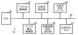
図2は本実施例の呼制御装置の構成の要部を表わしたものである。呼制御装置31はCPU(中央処理装置)41と、各種の制御プログラムを格納したプログラム格納部42と、通話のための音声データや制御データをパケット化したIP信号をLAN11を介して受信するIP信号受信部43と、IP信号の受信を管理するためのIP信号受信テーブル44と、このIP信号受信テーブル44に対して受信有り、あるいは受信無しを書き込むテーブル書込制御部45と、後に説明する定期診断のための定期診断信号送信部46と、タイマ回路としての応答待ちタイマ47ならびにこれら各部を接続するデータバス等のバス48とを備えている。なお、プログラム格納部42およびIP信号受信テーブル44は同一の記憶媒体上に構成されていてもよい。また、応答待ちタイマ47はソフトウェアで構成することができる。
【0029】
ここでは、図1に示した呼制御装置31の構成について具体的に示したが、電話網14等の他のネットワークを介して接続された他のLANにも同様の呼制御装置が接続されている。
【0030】
図3は、IP信号受信テーブルの構成を表わしたものである。IP信号受信テーブル44は、図1に示した呼制御装置31とLAN11を介してIP信号の送受信を行う可能性のあるすべてのネットワーク接続装置のID(識別情報)を示すID1、ID2、……ごとに受信有無情報51を格納するようになっている。受信有無情報51は具体的には受信があったことを示す「受信有り」と受信がないことを示す「受信無し」であり、たとえば信号の“1”と“0”で対応付けられている。
【0031】
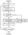
図4は呼制御装置の格納しているプログラムの1つを示したものである。図2に示した呼制御装置31内のプログラム格納部42には各種の制御手順が格納されているが、図2に示した制御手順は他のネットワーク接続装置からIP信号が送られてくるかどうかを所定の時間間隔でチェックする周期処理プログラムとなっている。すなわち、図2に示したCPU41は予め定めた周期の開始時点が到来すると、まずパラメータnを“1”に初期化して(ステップS61)、IDnに対応する受信有無情報51をIP信号受信テーブル44から読み出す(ステップS62)。そして、これが「受信無し」となっているかどうかを判別する(ステップS63)。なっていれば(Y)、該当する呼制御装置に対して定期診断処理を実行する(ステップS64)。これについては後に詳しく説明する。
【0032】
受信有無情報51がこれ以外の場合、すなわち「受信有り」となっていれば(ステップS63:N)、テーブル書込制御部45を制御してこれを「受信無し」に書き換える(ステップS65)。この場合、ステップ64の処理は行われない。「受信有り」となっているということは、前記した周期で定めた時間内に呼制御装置31がそのネットワーク接続装置からIP信号を受信したことである。これは、図2に示した呼制御装置31にIP信号を送信したネットワーク接続装置が障害を発生しておらず、かつLAN11から切り離されていないこと、すなわち正常であることを意味する。
【0033】
ステップS64の処理あるいはステップS65の処理が行われたら、パラメータnが“1”だけカウントアップされる(ステップS66)。そして、これによるパラメータnの値が図2に示した呼制御装置31とIP信号の通信を行う他のネットワーク接続装置の総数に到達したかどうかのチェックが行われる(ステップS67)。
【0034】
この値に到達していない場合には(ステップS67:N)、ステップS62に戻って次のネットワーク接続装置からのIP信号の受信の有無を確認する。そして前記したと同様の制御を繰り返すことになる。このようにしてLAN11に接続されたネットワーク接続装置の全数について受信有無情報51のチェックが終了したら(ステップS67:Y)、処理を終了する(エンド)。
【0035】
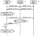
図5は、本実施例でネットワーク接続装置の1つが途中でLANから切り離されたときの、各ネットワーク接続装置のIP信号の送受信の様子を表わしたものである。ある時刻に図1に示した電話網14を介して図示しない他の電話機が発呼したものとし、これによるIP信号を呼制御装置31が受信したとする。通話先が既存電話機16であるとすると、呼制御装置31は着呼の応答を返すために着呼指示を加入者変換装置17に送る(ステップS71)。加入者変換装置17はLAN11上における呼制御プロトコルを既存電話機16における呼制御プロトコルに変換して、着呼指示を既存電話機16に送る(ステップS72)。既存電話機16はこれに対して着呼指示応答を行い(ステップS73)、加入者変換装置17はこれを変換して呼制御装置31に送出する(ステップS74)。
【0036】
この結果として、呼制御装置31は加入者変換装置17からIP信号が正常に受信されたことを判別し、IP信号受信テーブル44における加入者変換装置17のIDに対応付けた受信有無情報として「受信有り」を設定する(ステップS75)。この後、既存電話機16の通話が開始され、これが終了すると呼制御装置31は加入者変換装置17に復旧指示を行い(ステップS76)、加入者変換装置17はこれを既存電話機16に伝達する(ステップS77)。
【0037】
加入者変換装置17がこれ以後、何らかの原因でLAN11から切断されたとする(ステップS78)。すると次に呼制御装置31が同様に着呼指示を加入者変換装置17に送出しても(ステップS79)、これは加入者変換装置17に届かず、したがってステップS74で示したような着呼指示に対する応答もない。呼制御装置31は図2に示した応答待ちタイマ47が計時を終了するまでに着呼指示応答が加入者変換装置17から返って来ないときはIP信号受信テーブル44における加入者変換装置17のIDに対応付けた受信有無情報として「受信無し」を設定することになる(ステップS80)。この場合には、前記したように定期診断処理が行われることになる。
【0038】
図6は、ステップS64で示した定期診断処理を具体的に表わしたものである。今までの処理は図1に示した呼制御装置31が自装置内で独自に行った制御であり、LAN11に接続された他のネットワーク接続装置としてのゲートウェイ13、VoIP電話機15および加入者変換装置17に特別の負担を強いているものではない。定期診断処理は図4のステップS63で「受信無し」と判別されたネットワーク接続装置に対して個別に診断のためのパケット(以下、定期診断信号と称する。)を送出して異常の有無を確認する処理である。
【0039】
この定期診断処理が起動されると、図2に示したCPU41は定期診断信号送信部46から定期診断信号を送出する(ステップS91)。この定期診断信号は「受信無し」と判別されたネットワーク接続装置を宛先として、そのネットワーク接続装置からの返信を要求する信号である。ここでは、図5で説明した加入者変換装置17が「受信無し」と判別された場合を例にとって説明を行う。
【0040】
図2に示したCPU41は、定期診断信号を送出してから所定の時間t1が経過する前に(ステップS92:N)、該当のネットワーク接続装置としての加入者変換装置17から返答のIP信号が送り返されるかどうかを監視している(ステップS93)。そして、この返答のIP信号が送り返された場合には(Y)、その加入者変換装置17を正常(正常に復旧した場合も含む)と判断する。
【0041】
これに対して、所定の時間t1が経過するまでに定期診断信号に対する応答のIP信号が送られて来なかった場合には(ステップS92:Y)、リトライの回数を規定している場合にはその回数の上限に達するまで(ステップS94:Y)、ステップS91に戻って加入者変換装置17に対して定期診断信号を繰り返し送出して、応答の有無を確認する。リトライの回数の上限に達しても加入者変換装置17から定期診断信号に対する応答のIP信号が送られて来なかった場合には(ステップS94:N)、加入者変換装置17に異常が発生していると判別し、その旨の設定を行って(ステップS95)、処理を終了する(エンド)。
【0042】
このように異常を示す設定が行われた場合には、呼制御装置12から通信システムの管理者の電話機にその旨の通知が自動的に行われたり、アラームが表示されて、異常のあるネットワーク接続装置の復旧のための処理が行われることになる。
【0043】
なお、図6のステップS93で該当するネットワーク接続装置から応答のIP信号が送られて来た場合には、そのとき定期診断信号に応答するために送られてきたIP信号によって図3に示したIP信号受信テーブル44の該当欄が「受信無し」から「受信有り」に書き換えられている。これに対しては、次の周期までの監視を正確に行うために、この「受信有り」として書き換えられた内容をステップS93の処理の直後に「受信無し」にリセットするようにしてもよい。
【0044】
次に、図1に示した呼制御装置31自体が何らかの理由でLAN11から切り離されている場合もある。たとえば、LAN11との間の通信ケーブルが外れたり、断線を生じさせたような場合である。このような場合には、見かけ上はLAN11に接続された他のネットワーク接続装置がすべて応答信号を呼制御装置31に返さないような結果となる。そこで、このような場合には呼制御装置31自体の異常と判別することも可能である。他のネットワーク接続装置と送受信する回路部分に障害が発生した場合も同様である。
【0045】
図7は、これとは反対に他のネットワーク接続装置側が呼制御装置の異常を判別する処理の流れを表わしたものである。このような処理を行うネットワーク接続装置は、たとえばそのROM(リード・オンリ・メモリ)あるいは他の記憶媒体に所定のプログラムを格納しており、図示しないCPUが呼制御装置31自体の異常を監視するようになっている。また、この処理の前提として呼制御装置31が図6で示した定期診断処理を実行するものとする。これを加入者変換装置17が呼制御装置31を監視する例と共に説明する。
【0046】
加入者変換装置17は図5で説明したように呼制御装置31から着呼指示(ステップS71)と定期診断信号のいずれも来ない時間を図示しないタイマで計時している。そして、その時間が前記した周期よりも所定時間長い時間t2以上となったとき(ステップS101:Y)、呼制御装置31の現在の状態を異常と設定する(ステップS102)。これは、着呼指示が来ないことにより加入者変換装置17が着呼指示応答を行わなかった場合には、加入者変換装置17のIDに対応付けた受信有無情報として「受信無し」が設定されるので、前記した周期が到来した時点で呼制御装置31が定期診断信号を加入者変換装置17に対して送出するはずだからである。このような状況で定期診断信号が送られて来ない場合には、呼制御装置31に障害が発生したり、呼制御装置31がLAN11から切り離される等の異常が発生していると想定することができる。
【0047】
これに対して、時間t2が経過する前に着呼指示あるいは定期診断信号が到来した場合には(ステップS101:N)、その時点に前記したタイマをリセットして(ステップS103)、再びその時点から計時動作を再開することになる。
【0048】
【発明の効果】
以上説明したように請求項1〜請求項7記載の発明によれば、呼の接続の際の呼制御装置とネットワーク接続装置との間の信号の送受信を利用して、ネットワーク接続装置が障害を発生させていたりネットワークから切断されているといった異常の可能性を判別するので、この段階で特別な信号をネットワークに流すことなく、ネットワークに余分な負荷を掛けることがないばかりでなく、特別なハードウェアも必要としない。しかも、異常の可能性がある場合には診断手段が異常の有無の診断を行うことにしたので、診断の質を低下させることがない。
【0049】
また、請求項2記載の発明によれば、診断手段が、該当するネットワーク接続装置に対して応答を要求する定期診断信号を送出し、これに対してそのネットワーク接続装置が所定時間内に応答しなかったときに異常を検出することにしたので、特別に診断の時間が遅延することなく異常の可能性のあるネットワーク接続装置の診断が可能である。
【0050】
更に請求項3記載の発明によれば、定期診断信号に対する応答がなかった場合には、予め定めた回数だけ定期診断信号の送出を繰り返し行えるようにし、それでも応答がなかった場合にそのネットワーク接続装置に障害が発生していると判別することにして、障害の認定の信頼性を向上させている。
【0051】
また請求項4記載の発明によれば、着呼指示応答信号監視手段が各ネットワーク接続装置に対応させて応答の有り無しを記録する記憶手段を備えることにしたので、各ネットワーク接続装置の障害の有無をいつでも確認できると共に、内容の更新も容易である。
【0052】
更に請求項5記載の発明によれば、定期診断による応答を着呼指示信号に対する応答と区別することによって、次の周期でそのネットワーク接続装置に対して着呼指示信号が送られてきたときの応答の有無を記憶手段に正確に反映させることができる。
【0053】
また請求項6記載の発明では、ネットワーク接続装置は、予め定めた周期を超える所定の時間内に呼制御装置から着呼指示信号も定期診断信号も送られて来ないときその呼制御装置自体の異常を判別することにしたので、ネットワーク接続装置のみならず呼制御装置の異常の有無も判別することができる。
【図面の簡単な説明】
【図1】本発明の実施例における通信システムの要部を表わしたシステム構成図である。
【図2】実施例における呼制御装置の要部を表わしたブロック図である。
【図3】実施例のIP信号受信テーブルの構成を表わした説明図である。
【図4】実施例における周期処理プログラムによる処理を示す流れ図である。
【図5】実施例でネットワーク接続装置の1つが途中でLANから切り離されたときの各ネットワーク接続装置のIP信号の送受信の様子を表わした説明図である。
【図6】図4のステップS64で示した定期診断処理を具体的に表わした流れ図である。
【図7】本実施例で呼制御装置以外のネットワーク接続装置側が呼制御装置の異常を判別する処理の流れを表わした流れ図である。
【図8】従来の通信システムの要部を表わしたブロック図である。
【符号の説明】
11 LAN(ローカルエリアネットワーク)
13 ゲートウェイ(ネットワーク接続装置)
15 VoIP電話機(ネットワーク接続装置)
17 加入者変換装置(ネットワーク接続装置)
31 呼制御装置
41 CPU
42 プログラム格納部
43 IP信号受信部
44 IP信号受信テーブル
46 定期診断信号送信部
47 応答待ちタイマ
51 受信有無情報[0001]
BACKGROUND OF THE INVENTION
The present invention relates to a communication system such as a call system that makes a call using a network, and more particularly to a communication system that is connected to a network and can detect a failure of various devices that send a call control signal to the network.
[0002]
[Prior art]
2. Description of the Related Art A technique for transmitting and receiving audio data in packets using an IP protocol (Internet Protocol) in a network such as the Internet has attracted attention. If this technology called VoIP (Voice over Internet Protocol) is used, for example, a call between a geographically distant head office and each branch can be constructed in an inexpensive communication system using an always-on Internet connection service or a dedicated line. .
[0003]
FIG. 8 shows a main part of such a conventional communication system. A
[0004]
In such a conventional communication system, the
[0005]
Therefore, conventionally, a control signal for checking whether there is an abnormality has been periodically transmitted and received between these network connection devices connected to the
[0006]
[Problems to be solved by the invention]
A control signal for determining whether or not each network connection device is abnormal is transmitted as a packet signal on the
[0007]
In view of this, Japanese Patent Laid-Open No. 6-30116 discloses that a diagnostic task is executed when power is turned on to the main apparatus of the system. In this diagnostic task, each part (network connection device) that makes up the system is started and diagnosed, and these results are written to a single storage unit, and a timer is started each time a timeout occurs. Do.
[0008]
With such a technique disclosed in Japanese Patent Laid-Open No. 6-30116, although the burden on each network connection device can be reduced in that the diagnosis of each part is performed in a specially allocated time, There is a waste of using diagnostic control signals that are not directly related. In addition, since a special time for diagnosis is set, there is a problem that time for an original call or communication is restricted. Japanese Patent Laid-Open No. 8-317058 also has a similar problem because a loop for transmitting test data is formed and the test data is periodically sent to the loop.
[0009]
In the explanation of the abnormality, the problem of the call system was pointed out, but the same problem occurs in the entire communication system including the call.
[0010]
SUMMARY OF THE INVENTION An object of the present invention is to provide a communication system capable of detecting an abnormality of each device connected to a network using a signal used for communication such as a call on the network.
[0011]
[Means for Solving the Problems]
According to the first aspect of the present invention, (a) an incoming call instruction response signal is requested when an incoming call instruction signal connected to the network and sent to a call connection request destination is permitted. One or a plurality of network connection devices to be transmitted to the transmission destination, and (b) an incoming call instruction for transmitting an incoming call instruction signal to a device that is requested to connect a call among these one or a plurality of network connection devices These network connection devices determine whether or not a signal sending means and an incoming call instruction response signal in response to the incoming call instruction signal are sent from the one or more network connection devices as described above within a predetermined period. Incoming call instruction response signal monitoring means to be monitored separately, and diagnosis of presence / absence of abnormality of an apparatus that has not received an incoming call instruction response signal within a predetermined period within the network connection device To and a call control apparatus that includes a cross section in the communication system.
[0012]
That is, the invention described in
[0013]
In the invention according to
[0014]
That is, in the invention described in
[0015]
According to a third aspect of the present invention, in the communication system according to the second aspect, the periodic diagnostic signal transmitting means is means for repeatedly transmitting the periodic diagnostic signal a predetermined number of times when there is no response to the transmitted periodic diagnostic signal. In addition, the abnormality detection means is characterized in that an abnormality is detected when there is no response from the destination network connection device even if the periodic diagnostic signal is transmitted a predetermined number of times.
[0016]
That is, according to the third aspect of the invention, in consideration of the case where there is a situation where the diagnosis cannot be reliably performed by sending the periodic diagnostic signal once, if there is no response to the periodic diagnostic signal, the predetermined number of times is given. The periodic diagnosis signal can be repeatedly sent, and if there is still no response, it is determined that a failure has occurred in the network connection device, thereby improving the reliability of failure identification.
[0017]
According to a fourth aspect of the present invention, in the communication system according to the second aspect, the incoming call instruction response signal monitoring means sends a response to the incoming call instruction response signal or the periodic diagnosis signal for each of the one or more network connection devices. It is characterized by having storage means for recording whether or not to come.
[0018]
That is, the invention according to
[0019]
In the invention according to claim 5, in the communication system according to
[0020]
That is, according to the fifth aspect of the present invention, at the stage of sending a periodic diagnostic signal to a certain network connection device, writing is made to the effect that there is no response at the location corresponding to that network connection device in the storage means. When a response to the periodic diagnostic signal is sent, it is changed to a written content indicating that there is a response, but this is a response to the periodic diagnostic signal and not a response to the incoming call instruction signal. Therefore, it is assumed that there is no abnormality in the diagnosis of the network connection device, but the corresponding part of the storage means is returned to a state where there is no response. As a result, the presence or absence of a response when an incoming call instruction signal is sent to the network connection device in the next cycle is accurately reflected in the storage means.
[0021]
According to a sixth aspect of the present invention, in the communication system according to the second aspect, the network connection device receives an incoming call instruction signal and a periodic diagnosis signal from the call control device within a predetermined time exceeding a predetermined period. It is characterized by comprising a call control device abnormality determining means for determining abnormality of the call control device itself when there is not.
[0022]
That is, the invention according to claim 6 deals with determination of abnormality of the call control device itself. When a network connection device does not make any response in one cycle, the call control device performs a periodic diagnosis of the network connection device. This means that a certain network connection device has no chance of response. If the call control device is normal, it means that the call control device always sends a periodic diagnosis signal for periodic diagnosis to the network connection device. Therefore, if the call control device does not send a periodic diagnosis signal in this situation, it is determined that an abnormality has occurred in the call control device.
[0023]
According to a seventh aspect of the present invention, in the communication system according to the first aspect, the call control device is a call control device that performs call control by VoIP, and each network connection device and the call control device are connected to a local area network. It is characterized by being.
[0024]
That is, in the invention described in claim 7, as an example of the communication system, the call control device is a call control device that performs call control by VoIP, and each network connection device and the call control device are connected to a local area network. It is shown that.
[0025]
DETAILED DESCRIPTION OF THE INVENTION
[0026]
【Example】
Hereinafter, the present invention will be described in detail with reference to examples.
[0027]
FIG. 1 shows a main part of a communication system in an embodiment of the present invention. In FIG. 1, the same parts as those in FIG. 8 are denoted by the same reference numerals, and description thereof will be omitted as appropriate. In this embodiment, only the
[0028]
FIG. 2 shows a main part of the configuration of the call control device of this embodiment. The
[0029]
Here, the configuration of the
[0030]
FIG. 3 shows the configuration of the IP signal reception table. The IP signal reception table 44 is an ID indicating IDs (identification information) of all network connection devices that may transmit / receive IP signals to / from the
[0031]
FIG. 4 shows one of the programs stored in the call control device. Various control procedures are stored in the
[0032]
If the reception presence /
[0033]
When the process of step S64 or the process of step S65 is performed, the parameter n is incremented by “1” (step S66). Then, it is checked whether or not the value of the parameter n thus reached the total number of other network connection devices that perform IP signal communication with the
[0034]
If this value has not been reached (step S67: N), the process returns to step S62 to check whether an IP signal has been received from the next network connection device. Then, the same control as described above is repeated. When the check of the reception presence /
[0035]
FIG. 5 shows a state of transmission / reception of an IP signal of each network connection apparatus when one of the network connection apparatuses is disconnected from the LAN halfway in this embodiment. Assume that another telephone (not shown) makes a call via the
[0036]
As a result, the
[0037]
Assume that the
[0038]
FIG. 6 specifically shows the periodic diagnosis process shown in step S64. The processing so far is control performed independently by the
[0039]
When this periodic diagnosis process is started, the
[0040]
The
[0041]
In contrast, the predetermined time t 1 If an IP signal in response to the periodic diagnosis signal has not been sent before the elapse of time (step S92: Y), if the number of retries is specified, the upper limit of the number of times is reached (step S92: Y). S94: Y), returning to step S91, a periodic diagnostic signal is repeatedly sent to the
[0042]
When the setting indicating the abnormality is made in this way, the
[0043]
When a response IP signal is sent from the corresponding network connection device in step S93 in FIG. 6, the IP signal sent to respond to the periodic diagnosis signal at that time is shown in FIG. The corresponding column of the IP signal reception table 44 is rewritten from “no reception” to “reception”. In response to this, in order to accurately monitor until the next cycle, the content rewritten as “reception” may be reset to “no reception” immediately after the process of step S93.
[0044]
Next, the
[0045]
FIG. 7 shows the flow of processing in which the other network connection device side discriminates the abnormality of the call control device on the contrary. A network connection device that performs such processing stores a predetermined program in its ROM (read only memory) or other storage medium, for example, and a CPU (not shown) monitors the abnormality of the
[0046]
As described with reference to FIG. 5, the
[0047]
In contrast, time t 2 If an incoming call instruction or periodic diagnostic signal arrives before the elapse of time (step S101: N), the timer described above is reset at that time (step S103), and the clocking operation is restarted from that time again. become.
[0048]
【The invention's effect】
As described above, according to the first to seventh aspects of the present invention, the network connection device can be used for failure by utilizing the signal transmission / reception between the call control device and the network connection device at the time of call connection. Since the possibility of anomalies such as being generated or disconnected from the network is determined, a special signal is not sent to the network at this stage, and an extra load is not applied to the network. No wear is required. In addition, when there is a possibility of abnormality, the diagnosis means decides whether or not there is an abnormality, so that the quality of diagnosis does not deteriorate.
[0049]
According to the second aspect of the present invention, the diagnostic means sends a periodic diagnosis signal requesting a response to the corresponding network connection device, and the network connection device responds within a predetermined time. Since it is decided to detect an abnormality when there is no such error, it is possible to diagnose a network connection apparatus that may be abnormal without delaying the diagnosis time.
[0050]
According to the third aspect of the present invention, when there is no response to the periodic diagnosis signal, the periodic connection of the periodic diagnosis signal can be repeated a predetermined number of times. By determining that a fault has occurred, the reliability of fault certification is improved.
[0051]
According to the fourth aspect of the present invention, since the incoming call instruction response signal monitoring means includes the storage means for recording the presence / absence of a response corresponding to each network connection apparatus, The presence / absence can be confirmed at any time and the contents can be easily updated.
[0052]
Furthermore, according to the invention of claim 5, by distinguishing the response by the periodic diagnosis from the response to the incoming call instruction signal, the incoming call instruction signal is sent to the network connection device in the next cycle. The presence or absence of a response can be accurately reflected in the storage means.
[0053]
In the invention according to claim 6, when the network connection device does not receive an incoming call instruction signal or a periodic diagnosis signal from the call control device within a predetermined time exceeding a predetermined cycle, the network connection device itself Since the abnormality is determined, it is possible to determine whether there is an abnormality in the call control device as well as the network connection device.
[Brief description of the drawings]
FIG. 1 is a system configuration diagram showing a main part of a communication system in an embodiment of the present invention.
FIG. 2 is a block diagram illustrating a main part of the call control device according to the embodiment.
FIG. 3 is an explanatory diagram illustrating a configuration of an IP signal reception table according to the embodiment.
FIG. 4 is a flowchart showing processing by a periodic processing program in the embodiment.
FIG. 5 is an explanatory diagram illustrating a state of transmission / reception of an IP signal of each network connection device when one of the network connection devices is disconnected from the LAN in the middle in the embodiment.
FIG. 6 is a flowchart specifically showing the periodic diagnosis process shown in step S64 of FIG.
FIG. 7 is a flowchart showing a flow of processing in which a network connection apparatus side other than the call control apparatus determines an abnormality of the call control apparatus in this embodiment.
FIG. 8 is a block diagram showing a main part of a conventional communication system.
[Explanation of symbols]
11 LAN (Local Area Network)
13 Gateway (Network connection device)
15 VoIP telephone (network connection device)
17 Subscriber conversion device (network connection device)
31 Call control device
41 CPU
42 Program storage
43 IP signal receiver
44 IP signal reception table
46 Periodic diagnostic signal transmitter
47 Response wait timer
51 Information on presence / absence of reception
Claims (7)
これら1または複数のネットワーク接続装置のうちの呼の接続が要求された装置に対して前記着呼指示信号を送出する着呼指示信号送出手段と、前記1または複数のネットワーク接続装置から前記着呼指示信号に応答する形の着呼指示応答信号が予め定めた周期内に一度でも送られてくるかどうかをこれらのネットワーク接続装置別に監視する着呼指示応答信号監視手段と、前記ネットワーク接続装置の内で着呼指示応答信号が前記予め定めた周期内に一度も送られて来ない装置に対してその異常の有無の診断を行う診断手段とを備えた呼制御装置
とを具備することを特徴とする通信システム。One or a plurality of networks that send an incoming call instruction response signal to a destination of the request when the call connection is permitted with respect to the incoming call instruction signal that is connected to the network and sent to the request destination of the call connection A connecting device;
An incoming call instruction signal sending means for sending the incoming call instruction signal to a device that is requested to connect a call among the one or more network connection devices, and the incoming call from the one or more network connection devices. An incoming call instruction response signal monitoring means for monitoring whether the incoming call instruction response signal in response to the instruction signal is sent even once within a predetermined period, for each of these network connection apparatuses; And a call control device comprising diagnostic means for diagnosing the presence / absence of an abnormality of a device to which an incoming call instruction response signal has not been sent even once within the predetermined period. A communication system.
Priority Applications (1)
| Application Number | Priority Date | Filing Date | Title |
|---|---|---|---|
| JP2001140548A JP3666412B2 (en) | 2001-05-10 | 2001-05-10 | Communications system |
Applications Claiming Priority (1)
| Application Number | Priority Date | Filing Date | Title |
|---|---|---|---|
| JP2001140548A JP3666412B2 (en) | 2001-05-10 | 2001-05-10 | Communications system |
Publications (2)
| Publication Number | Publication Date |
|---|---|
| JP2002335327A JP2002335327A (en) | 2002-11-22 |
| JP3666412B2 true JP3666412B2 (en) | 2005-06-29 |
Family
ID=18987137
Family Applications (1)
| Application Number | Title | Priority Date | Filing Date |
|---|---|---|---|
| JP2001140548A Expired - Lifetime JP3666412B2 (en) | 2001-05-10 | 2001-05-10 | Communications system |
Country Status (1)
| Country | Link |
|---|---|
| JP (1) | JP3666412B2 (en) |
Families Citing this family (4)
| Publication number | Priority date | Publication date | Assignee | Title |
|---|---|---|---|---|
| JP2005237856A (en) * | 2004-02-27 | 2005-09-08 | Samii Kk | Game medium lending machine system |
| US7508817B2 (en) | 2005-02-08 | 2009-03-24 | At&T Intellectual Property I, L.P. | Method and apparatus for measuring data transport quality over an internet protocol |
| JP4502847B2 (en) * | 2005-03-08 | 2010-07-14 | Necフィールディング株式会社 | Voice network abnormality detection method, voice network abnormality detection apparatus and abnormality detection system |
| KR101002678B1 (en) | 2009-01-09 | 2010-12-20 | 알폰스테크(주) | VoIP Gateway and Voice Call Line Testing Method therof |
-
2001
- 2001-05-10 JP JP2001140548A patent/JP3666412B2/en not_active Expired - Lifetime
Also Published As
| Publication number | Publication date |
|---|---|
| JP2002335327A (en) | 2002-11-22 |
Similar Documents
| Publication | Publication Date | Title |
|---|---|---|
| EP1391079B1 (en) | Method and system for implementing a fast recovery process in a local area network | |
| US9332037B2 (en) | Method and apparatus for redundant signaling links | |
| JP4166939B2 (en) | Active fault detection | |
| US7352705B1 (en) | Method and apparatus for determining endpoints for use as testing devices | |
| JP2006013827A (en) | Packet transfer apparatus | |
| JPS63303537A (en) | Method of forming address table in ring type communication network | |
| US7697512B1 (en) | Proactive monitoring of status of voice-over-IP servers | |
| JP3666412B2 (en) | Communications system | |
| JP2006166244A (en) | Network telephone system, and main device of the network telephone system | |
| US7746949B2 (en) | Communications apparatus, system and method of creating a sub-channel | |
| JP2007529806A (en) | Fault management in a management system using Ethernet | |
| JP4967674B2 (en) | Media service system, media service device, and LAN redundancy method used therefor | |
| US6483855B1 (en) | Communication content recording apparatus and method | |
| JP4692419B2 (en) | Network device, redundant switching method used therefor, and program thereof | |
| JP4050849B2 (en) | Automatic meter reading system | |
| JP3567873B2 (en) | Wireless communication network and fault detection method used therefor | |
| JP3183275B2 (en) | Security monitoring system | |
| US6480576B1 (en) | Method and device for detecting path faults in a network | |
| JP2001060959A (en) | High reliability system | |
| JP3629151B2 (en) | Communication content recording apparatus and communication content recording method | |
| JP2024052734A (en) | Gateway device for identifying cause of failure in telephone communication, telephone system having the same, method for identifying cause of failure, and computer program | |
| JP3440743B2 (en) | Call receiving system | |
| KR20150057895A (en) | Apparatus and methdo for controlling access | |
| JP2508272B2 (en) | Message response monitoring device | |
| JP3547308B2 (en) | Subscriber line switching method |
Legal Events
| Date | Code | Title | Description |
|---|---|---|---|
| A977 | Report on retrieval |
Free format text: JAPANESE INTERMEDIATE CODE: A971007 Effective date: 20050301 |
|
| TRDD | Decision of grant or rejection written | ||
| A01 | Written decision to grant a patent or to grant a registration (utility model) |
Free format text: JAPANESE INTERMEDIATE CODE: A01 Effective date: 20050315 |
|
| A61 | First payment of annual fees (during grant procedure) |
Free format text: JAPANESE INTERMEDIATE CODE: A61 Effective date: 20050328 |
|
| R150 | Certificate of patent or registration of utility model |
Ref document number: 3666412 Country of ref document: JP Free format text: JAPANESE INTERMEDIATE CODE: R150 Free format text: JAPANESE INTERMEDIATE CODE: R150 |
|
| S111 | Request for change of ownership or part of ownership |
Free format text: JAPANESE INTERMEDIATE CODE: R313111 |
|
| R350 | Written notification of registration of transfer |
Free format text: JAPANESE INTERMEDIATE CODE: R350 |
|
| FPAY | Renewal fee payment (event date is renewal date of database) |
Free format text: PAYMENT UNTIL: 20080415 Year of fee payment: 3 |
|
| FPAY | Renewal fee payment (event date is renewal date of database) |
Free format text: PAYMENT UNTIL: 20090415 Year of fee payment: 4 |
|
| FPAY | Renewal fee payment (event date is renewal date of database) |
Free format text: PAYMENT UNTIL: 20100415 Year of fee payment: 5 |
|
| FPAY | Renewal fee payment (event date is renewal date of database) |
Free format text: PAYMENT UNTIL: 20110415 Year of fee payment: 6 |
|
| FPAY | Renewal fee payment (event date is renewal date of database) |
Free format text: PAYMENT UNTIL: 20120415 Year of fee payment: 7 |
|
| FPAY | Renewal fee payment (event date is renewal date of database) |
Free format text: PAYMENT UNTIL: 20120415 Year of fee payment: 7 |
|
| FPAY | Renewal fee payment (event date is renewal date of database) |
Free format text: PAYMENT UNTIL: 20130415 Year of fee payment: 8 |
|
| FPAY | Renewal fee payment (event date is renewal date of database) |
Free format text: PAYMENT UNTIL: 20130415 Year of fee payment: 8 |
|
| FPAY | Renewal fee payment (event date is renewal date of database) |
Free format text: PAYMENT UNTIL: 20140415 Year of fee payment: 9 |
|
| S533 | Written request for registration of change of name |
Free format text: JAPANESE INTERMEDIATE CODE: R313533 |
|
| R350 | Written notification of registration of transfer |
Free format text: JAPANESE INTERMEDIATE CODE: R350 |