JP3664759B2 - Flash prevention device - Google Patents
Flash prevention device Download PDFInfo
- Publication number
- JP3664759B2 JP3664759B2 JP31298894A JP31298894A JP3664759B2 JP 3664759 B2 JP3664759 B2 JP 3664759B2 JP 31298894 A JP31298894 A JP 31298894A JP 31298894 A JP31298894 A JP 31298894A JP 3664759 B2 JP3664759 B2 JP 3664759B2
- Authority
- JP
- Japan
- Prior art keywords
- deaerator
- water
- pipe
- storage tank
- water supply
- Prior art date
- Legal status (The legal status is an assumption and is not a legal conclusion. Google has not performed a legal analysis and makes no representation as to the accuracy of the status listed.)
- Expired - Fee Related
Links
Images


Description
【0001】
【産業上の利用分野】
本発明は汽力発電プラント等の給水設備に係わり、特にプラントの負荷しゃ断時等の急激な負荷降下過程にて発生する脱気器フラッシュ現象を防止するフラッシュ防止装置に関する。
【0002】
【従来の技術】
汽力発電プラントでは、プラントの負荷しゃ断時等の急激な負荷降下にて脱気器貯水タンク内にてフラッシュ現象が発生することがある。
また、ユニット起動時の給水ポンプ起動時に脱気器降水管及び給水ポンプ連絡管にてフラッシュ現象が発生する場合もある。
【0003】
このフラッシュ現象を従来給水設備系統の一部を示す図7を参照して以下に説明する。
図7に示す様に、従来の給水設備においては、脱気器1及び脱気器貯水タンク2は給水ブースタポンプ3の吸込圧力を確保する為に給水ブースタポンプ3より高い位置に設置されている。給水は復水器(図示せず)から脱気器水位調節弁5、低圧ヒータ8を介して給水配管17から脱気器1へ導かれ、この脱気器1で加熱脱気された給水は脱気器貯水タンク2へ導かれている。通常、復水器から導かれる給水はプラント負荷運転時は脱気器1の器内圧力の飽和温度とほぼ等しい温度となっている。この給水を脱気器貯水タンク2に溜め脱気器貯水タンク2内給水量は脱気器水位調節弁5により一定に保たれている。そして、この脱気器貯水タンク2内の給水は脱気器降水管15から給水ブースタポンプ3、給水ポンプ連絡管11、主給水ポンプ4を介して昇圧され供給配管18からボイラ(図示せず)へ給水される構成となっている。この供給配管18の主給水ポンプ4の下流側には再循環配管19が接続されており、この再循環配管19は給水ポンプ再循環弁12を介して脱気器貯水タンク2の上部に接続されている。
【0004】
さらに、脱気器降水管15には脱気器循環配管20および脱気器ブロー回収配管21が接続されており、脱気器循環配管20は脱気器循環ポンプ13を介して給水配管17の低圧ヒータ8下流側に接続され、脱気器ブロー回収配管21は脱気器ブロー回収弁7を介して復水器に接続されている。
【0005】
以上の構成において、負荷しゃ断時等の急激な負荷降下が発生した場合には、脱気器1への加熱蒸気源であるタービン抽気がしゃ断され、脱気器1の器内圧力が急激に低下し、脱気器貯水タンク2の給水温度は脱気器1の器内圧力の飽和温度より高くなってしまい、フラッシュ現象が発生する。同様にプラント停止過程においても脱気器1へのタービン抽気の減少により、器内圧力の降下スピードが脱気器貯水タンク2内の給水温度の降下スピードより速い為、脱気器貯水タンク2の給水温度は脱気器1の器内圧力の飽和温度より高くなってしまいフラッシュ現象が発生する。
【0006】
従来、この様なフラッシュ現象を防止する為、実開昭53−101101号に記載されているように、脱気器1の器内圧力が低下した場合、脱気器1への蒸気源として抽気配管24に接続された補助蒸気配管25から補助蒸気調節弁9を介して補助蒸気を供給し器内圧力の低下を防止していた。
【0007】
【発明が解決しようとする課題】
しかし、脱気器への蒸気源として用いる補助蒸気量には限度があり、急激な脱気器の器内圧力を防止する為の必要量が確保できず脱気器の器内圧力の低下を完全に防止することが出来ずフラッシュ現象が発生するおそれがあった。
【0008】
また、主給水ポンプ起動の際に、脱気器降水管及び給水ポンプ連絡管に滞留していた給水も同様にフラッシュし、管内にて気体と液体に分離し主給水ポンプ起動時に停止時間によっては、起動時の気体部への給水の突入によりハンマリングを起こす可能性があった。
【0009】
この様なフラッシュ現象が発生すると、脱気器貯水タンクの水位が不安定となり、水位低により主給水ポンプトリップまたは脱気器降水管及び給水ポンプ連絡管にてハンマリング等のトラブルを起こすおそれがあった。
【0010】
本発明は、これらの課題を解決するためになされたものであり脱気器、脱気器降水管、給水ポンプ連絡管にてフラッシュ現象が生じない様にしたフラッシュ防止装置を提供することにある。
【0011】
【課題を解決するための手段】
上記目的を達成するために請求項1に係る本発明は、脱気器、脱気器降水管、給水ポンプ連絡管にて発生するフラッシュ現象を防止する為に、脱気器貯水タンクより脱気器降水管を経て主給水ポンプへ給水を供給する給水設備において、急激な負荷降下が発生した場合に脱気器降水管より分岐し復水器へ接続されている脱気器ブロー回収管に調節弁を設け、脱気器貯水タンク内の給水を急速に置換する制御を行うフラッシュ防止装置を提供する。
【0012】
【作用】
上記構成による請求項1記載の本発明のフラッシュ防止装置によれば、急激な負荷降下が発生した時に脱気器への復水の流入量を許容できる最大とし、脱気器貯水タンク内の給水を復水器へ排出することで脱気器貯水タンク内の給水を短時間にて置換し脱気器貯水タンク内給水の温度を下げることによりフラッシュ現象を防止することができる。
【0013】
【実施例】
以下、本発明の実施例を図面を参照して説明する。
図1は本発明の第1実施例を示す脱気器フラッシュ防止装置の系統構成図である。なお、図1において、図7と同一部分には同一符号を付し、その部分の構成の説明は省略する。図1において、脱気器1及び脱気器貯水タンク2は、給水ブースタポンプ3の吸込圧力を確保する為に給水ブースタポンプ3より高い位置に設置されている。この構成は従来例と同一であるが、本発明では脱気器貯水タンク2から給水ブースタポンプ3に至る脱気器降水管15の途中からプラント停止中に脱気器貯水タンク2内給水を排出する為に設けられている脱気器ブロー回収配管21に配設された脱気器ブロー回収弁7をバイパスするバイパス配管22をこの脱気器ブロー回収配管21に設け、このバイパス配管22に脱気器ブロー調節弁6を設置している。そして、脱気器貯水タンク2には高圧ヒータドレン回収弁10を介して高圧ヒータドレン回収配管23が接続されている。さらに、脱気器1には抽気が導かれる抽気配管24が接続されており、この抽気配管24には補助蒸気調節弁9を介して補助蒸気配管25が接続されている。そして、この構成によって、本実施例は図2のように制御される。図2において負荷しゃ断時等の負荷降下が発生した場合、通常脱気器貯水タンク2内の給水を一定レベルに制御している(ブロックA)脱気器水位調節弁5aを強制的に全開とし(ブロックB)、脱気器ブロー調節弁6を全閉状態(ブロックC)から脱気器貯水タンク2内レベルを制御するモード(ブロックD)に移行される。
【0014】
すなわち、脱気器水位調節弁5aを強制開することで脱気器1及び脱気器貯水タンク2へ給水を流しえる最大の流量にて供給し、脱気器ブロー調節弁6にて脱気器貯水タンク2内の給水を排出することで脱気器貯水タンク2内の給水を短時間で置換させることができる。この様に脱気器貯水タンク2内の給水を置換することにより脱気器貯水タンク2内の給水の温度を下げ、脱気器貯水タンク2内の給水を脱気器1の器内圧力の飽和温度以下にすることでフラッシュ現象の防止を図ることができる。
【0015】
なお、図2に示されるように、負荷しゃ断等の信号が解除されれば、NOT回路E,Fによって通常モードとなり脱気器ブロー調節弁6が閉止され、脱気器水位調節弁5aが脱気器貯水タンク2の水位制御に変更される。
【0016】
次に本発明の第2実施例を図1及び図3を参照して説明する。
図1は本発明の第2実施例の系統構成図であり、この構成は第1の実施例と同一であるので構成の説明は省略する。本発明では、図3に示すようにボイラの上流側に配設されボイラに導入される給水を昇温させる高圧ヒータで凝縮された高温水である高圧ヒータドレン水を脱気器貯水タンク2へ回収している高圧ヒータドレン回収配管23に配設され通常時全開状態である(ブロックG)、高圧ヒータドレン回収弁10を、負荷しゃ断等の急激な負荷降下が発生した時に強制閉する(ブロックH)。すなわち、脱気器貯水タンク2への高温水の流入を防ぐことにより、脱気器貯水タンク2内の給水温度の低下を図り、脱気器1の器内圧力を飽和温度以下にすることでフラッシュ現象を防止することができる。
【0017】
なお、図3に示すように負荷しゃ断信号が解除されれば、NOT回路Iによって通常モードとなり、高圧ヒータドレン回収弁10は全開制御される。
次に本発明の第3実施例を図4を参照して説明する。なお図4において、図7と同一部分には同一符号を付し、その部分の構成の説明は省略する。
【0018】
図4は本発明の第3実施例の系統構成図であり、図4において給水ブースタポンプ3と主給水ポンプ4との間の給水ポンプ連絡管11には給水ポンプ連絡管11、脱気器降水管15及び脱気器貯水タンク2内給水を排出する脱気器ブロー配管26が脱気器ブロー調節弁6aを介して接続されている。そしてこの脱気器ブロー配管26によって主給水ポンプ4および給水ブースタポンプ3停止時に給水を排出することにより給水ポンプ連絡管11及び脱気器降水管15内の給水を絶えず置換する。すなわち、脱気器貯水タンク2内給水を絶えず脱気器降水管15および給水ポンプ連絡管11に流し続けることにより滞留水のフラッシュを防止し、主給水ポンプ4および給水ブースタポンプ3起動時に脱気器降水管15及び給水ポンプ連絡管11でのハンマリングを防止することができる。
【0019】
次に本発明の第4実施例を図5及び図6を参照して説明する。なお、図5において、図7と同一部分には同一符号を付し、その部分の構成の説明は省略する。図5は本発明の第4実施例の系統構成図であり、図5において主給水ポンプ4の出口側供給配管18より脱気器貯水タンク2へ主給水ポンプ4の最低流量を確保できるよう給水を排出する給水ポンプ再循環配管19に給水ポンプ再循環弁12をバイパスする循環弁バイパス配管27を接続し、脱気器循環ポンプ出、入口弁16,14を介して脱気器循環ポンプ28を設置している。
【0020】
以上の構成における第4実施例の制御回路を図6を参照して説明する。
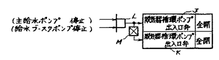
主給水ポンプ4と給水ブースタポンプ3が停止中に脱気器循環ポンプ出入口弁16,14を全開にし、脱気器循環ポンプ28を起動させる(ブロックJ)。また、主給水ポンプ4又は給水ブースタポンプ3が起動すると脱気器循環ポンプ出入口弁16,14を全閉し給水は給水ポンプ再循環弁12により制御される(ブロックK)。なお、図中LはAND回路、MはNOT回路を示している。
【0021】
よって、脱気器循環ポンプ28を主給水ポンプ停止中に運転することにより、脱気器貯水タンク2内の給水を脱気器降水管15及び給水ポンプ連絡管11に通水することにより、滞留水によるフラッシュを防止し、主給水ポンプ起動時のハンマリング現象を防止することができる。
【0022】
【発明の効果】
以上説明したように、請求項1に係る本発明によれば脱気器貯水タンク内の給水温度を脱気器器内圧力の飽和温度低下に保つことができ、負荷しゃ断等の急激な負荷降下時に脱気器貯水タンク内でのフラッシュ現象を防止できる。
【図面の簡単な説明】
【図1】本発明の第1および第2の実施例を示すフラッシュ防止装置の系統構成図。
【図2】本発明の第1実施例に適用する制御回路図。
【図3】本発明の第2実施例に適用する制御回路図。
【図4】本発明の第3実施例を示すフラッシュ防止装置の系統構成図。
【図5】本発明の第4実施例を示すフラッシュ防止装置の系統構成図。
【図6】本発明の第4実施例に適用する制御回路図。
【図7】フラッシュ防止装置の従来例を示す系統構成図。
【符号の説明】
1…脱気器
2…脱気器貯水タンク
3…給水ブースタポンプ
4…主給水ポンプ
5,5a…脱気器水位調節弁
6,6a…脱気器ブロー調節弁
7…脱気器ブロー回収弁
8…低圧ヒータ
9…補助蒸気調節弁
10…高圧ヒータドレン回収弁
11…給水ポンプ連絡管
12…給水ポンプ再循環弁
13,28…脱気器循環ポンプ
14…脱気器循環ポンプ出口弁
15…脱気器降水管
16…脱気器循環ポンプ入口弁
17…給水配管
18…供給配管
19…再循環配管
20…脱気器循環配管
21…脱気器ブロー回収配管
22…バイパス配管
23…高圧ヒータドレン回収配管
24…抽気配管
25…補助蒸気配管
26…脱気器ブロー配管
27…循環弁バイパス配管[0001]
[Industrial application fields]
The present invention relates to a water supply facility such as a steam power plant, and more particularly to a flash prevention device for preventing a deaerator flash phenomenon that occurs in a sudden load drop process such as when a load of a plant is cut off.
[0002]
[Prior art]
In a steam power plant, a flash phenomenon may occur in the deaerator water storage tank due to a sudden load drop when the load of the plant is cut off.
In addition, a flash phenomenon may occur in the deaerator downcomer pipe and the feed water pump connecting pipe when the feed water pump is started up when the unit is started up.
[0003]
This flash phenomenon will be described below with reference to FIG. 7 showing a part of a conventional water supply system.
As shown in FIG. 7, in the conventional water supply equipment, the
[0004]
Further, a
[0005]
In the above configuration, when a sudden load drop occurs, such as when the load is cut off, the turbine bleeder, which is a heating steam source to the
[0006]
Conventionally, in order to prevent such a flash phenomenon, as described in Japanese Utility Model Laid-Open No. 53-101101, when the internal pressure of the
[0007]
[Problems to be solved by the invention]
However, there is a limit to the amount of auxiliary steam that can be used as a steam source for the deaerator, and it is not possible to secure the necessary amount to prevent sudden internal pressure of the deaerator. There was a possibility that the flash phenomenon could not be completely prevented.
[0008]
In addition, when the main feed pump is started, the feed water staying in the deaerator downcomer pipe and feed pump connection pipe is also flushed, and separated into gas and liquid in the pipe, depending on the stop time when the main feed pump is started. There was a possibility that hammering might occur due to the water supply entering the gas section at the time of startup.
[0009]
When such a flush phenomenon occurs, the water level in the deaerator water storage tank becomes unstable, and there is a risk of causing problems such as hammering in the main feed pump trip or deaerator downcomer pipe and feed pump connection pipe due to low water level. there were.
[0010]
The present invention has been made to solve these problems, and it is an object of the present invention to provide a flash prevention device that prevents a flash phenomenon from occurring in a deaerator, a deaerator downpipe, and a feed water pump connecting pipe. .
[0011]
[Means for Solving the Problems]
In order to achieve the above object, the present invention according to
[0012]
[Action]
According to the flash prevention device of the present invention as set forth in
[0013]
【Example】
Embodiments of the present invention will be described below with reference to the drawings.
FIG. 1 is a system configuration diagram of a deaerator flush prevention device showing a first embodiment of the present invention. In FIG. 1, the same parts as those in FIG. 7 are denoted by the same reference numerals, and description of the configuration of those parts is omitted. In FIG. 1, the
[0014]
That is, the deaerator water level control valve 5a is forcibly opened to supply the
[0015]
As shown in FIG. 2, when the signal such as the load cutoff is released, the normal mode is set by the NOT circuits E and F, the deaerator blow control valve 6 is closed, and the deaerator water level control valve 5a is released. It is changed to the water level control of the
[0016]
Next, a second embodiment of the present invention will be described with reference to FIGS.
FIG. 1 is a system configuration diagram of the second embodiment of the present invention. Since this configuration is the same as that of the first embodiment, description of the configuration is omitted. In the present invention, as shown in FIG. 3, the high-pressure heater drain water, which is high-temperature water condensed by a high-pressure heater that is arranged upstream of the boiler and raises the temperature of the feed water introduced into the boiler, is recovered in the deaerator
[0017]
If the load cutoff signal is canceled as shown in FIG. 3, the NOT circuit I enters the normal mode, and the high-pressure heater
Next, a third embodiment of the present invention will be described with reference to FIG. In FIG. 4, the same parts as those in FIG. 7 are denoted by the same reference numerals, and description of the structure of those parts is omitted.
[0018]
FIG. 4 is a system configuration diagram of the third embodiment of the present invention. In FIG. 4, a feed water
[0019]
Next, a fourth embodiment of the present invention will be described with reference to FIGS. In FIG. 5, the same parts as those in FIG. 7 are denoted by the same reference numerals, and description of the configuration of those parts is omitted. FIG. 5 is a system configuration diagram of the fourth embodiment of the present invention. In FIG. 5, water is supplied so that the minimum flow rate of the
[0020]
The control circuit of the fourth embodiment having the above arrangement will be described with reference to FIG.
While the
[0021]
Therefore, by operating the deaerator circulation pump 28 while the main feed water pump is stopped, the feed water in the deaerator
[0022]
【The invention's effect】
As described above, according to the first aspect of the present invention, the feed water temperature in the deaerator water storage tank can be maintained at the saturation temperature drop of the deaerator pressure, and a sudden load drop such as load cutoff Sometimes flushing in the deaerator water tank can be prevented.
[Brief description of the drawings]
FIG. 1 is a system configuration diagram of a flash prevention apparatus showing first and second embodiments of the present invention.
FIG. 2 is a control circuit diagram applied to the first embodiment of the present invention.
FIG. 3 is a control circuit diagram applied to a second embodiment of the present invention.
FIG. 4 is a system configuration diagram of a flash prevention apparatus showing a third embodiment of the present invention.
FIG. 5 is a system configuration diagram of a flash prevention apparatus showing a fourth embodiment of the present invention.
FIG. 6 is a control circuit diagram applied to a fourth embodiment of the present invention.
FIG. 7 is a system configuration diagram showing a conventional example of a flash prevention device.
[Explanation of symbols]
DESCRIPTION OF
Claims (1)
Priority Applications (1)
| Application Number | Priority Date | Filing Date | Title |
|---|---|---|---|
| JP31298894A JP3664759B2 (en) | 1994-12-16 | 1994-12-16 | Flash prevention device |
Applications Claiming Priority (1)
| Application Number | Priority Date | Filing Date | Title |
|---|---|---|---|
| JP31298894A JP3664759B2 (en) | 1994-12-16 | 1994-12-16 | Flash prevention device |
Publications (2)
| Publication Number | Publication Date |
|---|---|
| JPH08170805A JPH08170805A (en) | 1996-07-02 |
| JP3664759B2 true JP3664759B2 (en) | 2005-06-29 |
Family
ID=18035891
Family Applications (1)
| Application Number | Title | Priority Date | Filing Date |
|---|---|---|---|
| JP31298894A Expired - Fee Related JP3664759B2 (en) | 1994-12-16 | 1994-12-16 | Flash prevention device |
Country Status (1)
| Country | Link |
|---|---|
| JP (1) | JP3664759B2 (en) |
Families Citing this family (3)
| Publication number | Priority date | Publication date | Assignee | Title |
|---|---|---|---|---|
| JP4633493B2 (en) * | 2005-02-14 | 2011-02-16 | 株式会社日立製作所 | Method for preventing water hammer of deaerator and boiler water supply device |
| JP4949712B2 (en) * | 2006-03-28 | 2012-06-13 | 三菱重工業株式会社 | Power plant water supply equipment |
| JP7093319B2 (en) * | 2019-02-21 | 2022-06-29 | 三菱重工業株式会社 | Operation method of condensate water supply system of thermal power plant and condensate water supply system of thermal power plant |
-
1994
- 1994-12-16 JP JP31298894A patent/JP3664759B2/en not_active Expired - Fee Related
Also Published As
| Publication number | Publication date |
|---|---|
| JPH08170805A (en) | 1996-07-02 |
Similar Documents
| Publication | Publication Date | Title |
|---|---|---|
| JP4191894B2 (en) | Method of operating gas / steam combined turbine facility and gas / steam combined turbine facility for implementing the method | |
| JPS6136121B2 (en) | ||
| JP3664759B2 (en) | Flash prevention device | |
| JPH044481B2 (en) | ||
| JP2614350B2 (en) | Feed water heater drain pump up system | |
| JP2006220393A (en) | Water hammering prevention method for deaerator, and boiler feed water device | |
| JP3619551B2 (en) | Water supply equipment in a steam turbine plant | |
| JP3597683B2 (en) | Nuclear power plant | |
| JP5330730B2 (en) | Plant piping equipment | |
| JP3819161B2 (en) | Feed water heater drain discharge device | |
| JP2519282B2 (en) | Deaerator water level control system | |
| JPH04334506A (en) | Drain piping of auxiliary steam device of steam turbin equipment | |
| JP2650477B2 (en) | Water hammer prevention method for deaerator water supply piping and piping equipment therefor | |
| JP3317536B2 (en) | Saturated drain discharge piping system | |
| JPH0282003A (en) | Vent system of supply water heater of power plant by steam turbine | |
| JP2597594B2 (en) | Feed water heater drain injection device | |
| JPH09195713A (en) | Moisture content separation heater | |
| JPS60219404A (en) | Stabilizing device of deaerator output | |
| JP2003021305A (en) | Boiler feed water supply system | |
| JPH0663607B2 (en) | Turbine plant with feedwater heater drain injection device | |
| JP3067053B2 (en) | Condenser | |
| JP2637194B2 (en) | Combined plant startup bypass system and its operation method | |
| JPH06207704A (en) | Water hammering prevention device for water supply device | |
| JP2909301B2 (en) | How to pump up the feedwater heater drain | |
| JP2909300B2 (en) | Heater drain equipment |
Legal Events
| Date | Code | Title | Description |
|---|---|---|---|
| A131 | Notification of reasons for refusal |
Free format text: JAPANESE INTERMEDIATE CODE: A131 Effective date: 20041012 |
|
| A521 | Written amendment |
Free format text: JAPANESE INTERMEDIATE CODE: A523 Effective date: 20041213 |
|
| TRDD | Decision of grant or rejection written | ||
| A01 | Written decision to grant a patent or to grant a registration (utility model) |
Free format text: JAPANESE INTERMEDIATE CODE: A01 Effective date: 20050329 |
|
| A61 | First payment of annual fees (during grant procedure) |
Free format text: JAPANESE INTERMEDIATE CODE: A61 Effective date: 20050330 |
|
| RD02 | Notification of acceptance of power of attorney |
Free format text: JAPANESE INTERMEDIATE CODE: A7422 Effective date: 20050414 |
|
| A072 | Dismissal of procedure |
Free format text: JAPANESE INTERMEDIATE CODE: A072 Effective date: 20050610 |
|
| LAPS | Cancellation because of no payment of annual fees |