JP3664110B2 - Object type determination device and object type determination method - Google Patents
Object type determination device and object type determination method Download PDFInfo
- Publication number
- JP3664110B2 JP3664110B2 JP2001203514A JP2001203514A JP3664110B2 JP 3664110 B2 JP3664110 B2 JP 3664110B2 JP 2001203514 A JP2001203514 A JP 2001203514A JP 2001203514 A JP2001203514 A JP 2001203514A JP 3664110 B2 JP3664110 B2 JP 3664110B2
- Authority
- JP
- Japan
- Prior art keywords
- vehicle
- detection
- stop
- host vehicle
- sign
- Prior art date
- Legal status (The legal status is an assumption and is not a legal conclusion. Google has not performed a legal analysis and makes no representation as to the accuracy of the status listed.)
- Expired - Fee Related
Links
Images


Description
【0001】
【発明の属する技術分野】
本発明は、車両に搭載されて非可視光のレーザ光や電波等を放出し車両前方に存在する物体による反射波から物体の有無を検出し、検出した物体から走行車両、標識などを判別する物体種別判定装置及び物体種別判定方法に関する。
【0002】
【従来の技術】
従来、レーダを用いて物体の種別を判定する物標判定装置としては、例えば、特開2000−132799号公報に開示された制御対象選別装置がある。
【0003】
この制御対象選別装置は、距離計測手段を備え、まず、距離計測手段で計測したデータに応じて複数の距離グループに纏めることで検出グループを生成する。
【0004】
制御対象選別装置は、検出グループの生成を距離計測毎に行い、それぞれの検出グループの位置や動きによってさらにグループ化して、一つの物体として認識する。
【0005】
そして制御対象選別装置は、認識した物体を動きと、物体の幅によって先行車であるか、デリニエイタであるか、標識であるかの判断をしている。
【0006】
【発明が解決しようとする課題】
従来の物体の種別を判定する物標判定装置である制御対象選別装置は、検出した物体の位置と動き及び物体の幅といった情報で物体の種別を判定している。
【0007】
しかし、このような手法による物体の種別の判定では、例えば、自車両の前に先行して走行する車両が存在しない場合、高速道路上で遠方の頭上に行き先等を表示した案内標識は車両より明らかに大きいため停止車両と判定することはないが、普通車両と同等もしくは大型トラックと同等の標識は停止車両であるのか、標識であるのかを判定することは非常に困難である。
【0008】
したがって、従来の手法では、自車線前方にある停止物体を車両と標識とに区別することはできないといった問題がある。
【0009】
本発明は、上述した実情に鑑みて提案されたものであり、検出した物体を走行車両、停止物体とに的確に識別することができる物体種別判定装置及び物体種別判定方法を提供するものである。
【0010】
【課題を解決するための手段】
請求項1に係る発明では、上述の課題を解決するために、自車両に搭載されて自車両前方に存在する物体の種別を判定する物体種別判定装置であって、自車両前方に存在する上記物体に送信波を走査させ、上記物体から反射される反射波を検出し、検出した反射波に基づいて、上記自車両に対する物体位置を示す複数の検出点を生成する物体位置検出手段と、自車両前方に存在する上記物体の自車両に対する相対速度を上記物体位置検出手段で検出された各検出点ごとに検出する相対速度検出手段と、上記物体位置検出手段により生成した各検出点の物体位置、及び上記相対速度検出手段で検出した各検出点の相対速度に基づくグループ化処理を行って、複数の検出点の検出点群からなる上記物体を検出する物体検出手段と、上記物体検出手段で検出された物体を示す検出点群の相対速度に基づいて、上記物体が走行車両であるのか、停止物体であるのかの判定をする第1判定手段と、上記第1判定手段によって上記物体が停止物体であると判定され、上記停止物体と、自車両との間に走行車両が存在する場合、上記停止物体を頭上標識であると判定する第2判定手段と、上記各物体についての最大検出点数と、上記物体位置検出手段で検出された検出点数との割合を示すデータ充填率を算出する演算手段と、上記第1判定手段によって上記物体が停止物体であると判定され、上記停止物体と、自車両との間に走行車両が存在しない場合、上記演算手段によって算出されたデータ充填率に基づいて上記停止物体の種別を判定する第3判定手段とを備える。
【0011】
請求項2に係る発明では、上記演算手段は、上記検出点数をn、上記検出点の自車両との距離の平均値をZ、物体を示す検出点の端部幅をW、上記物体位置検出手段が上記物体を走査する角度をθとした場合に、上記データ充填率を
(n×Z×tanθ)/W
で表現される式を用いて演算する。
【0012】
請求項3に係る発明では、上記第2判定手段は、判定対象である停止物体と、上記自車両との間にある上記走行車両を示す検出点群のばらつきが大きい場合にのみ上記停止物体を頭上標識であると判定する。
【0013】
請求項4に係る発明では、上記第3判定手段は、上記停止物体を示す検出点群の相対速度、幅、上記反射強度、データ充填率に基づいて、停止車両、大標識、小標識/デリニエイタのいずれかの種別に分類する判定をする。
【0014】
請求項5に係る発明では、上記第3判定手段は、上記物体位置検出手段の走査範囲内に他の物体が存在しない場合に上記停止物体を停止車両と判定し、走査範囲内に他の物体が存在する場合に上記停止物体を大標識と判定する。
【0015】
請求項6に係る発明では、上記第3判定手段は、上記停止物体が小標識/デリニエイタであると判定された場合、判定処理を判定処理回数が所定の回数となるまで継続させる。
【0016】
請求項7に係る発明では、上述の課題を解決するために、自車両に搭載されて自車両前方に存在する物体の種別を判定する物体種別判定方法であって、自車両前方に存在する上記物体に送信波を走査させ、上記物体から反射される反射波を検出し、検出した反射波に基づいて、上記自車両に対する物体位置を示す複数の検出点を生成すると共に、自車両前方に存在する上記物体の自車両に対する相対速度を各検出点ごとに検出し、上記各検出点の物体位置、及び各検出点の相対速度に基づくグループ化処理を行って、複数の検出点の検出点群からなる上記物体を検出し、上記物体を示す検出点群の相対速度に基づいて、上記物体が走行車両であるのか、停止物体であるのかの判定をし、上記物体が停止物体であると判定され、上記停止物体と、自車両との間に走行車両が存在する場合、上記停止物体を頭上標識であると判定し、上記各物体についての最大検出点数と、上記検出点数との割合を示すデータ充填率を算出し、上記物体が相対速度に基づいて停止物体であると判定され、上記停止物体と上記自車両との間に走行車両がない場合、少なくとも上記算出されたデータ充填率に基づいて上記停止物体を停止車両、大標識、小標識/デリニエイタのいずれかの種別に判定する。
【0017】
【発明の効果】
請求項1に係る発明によれば、停止物体と自車両との間にスキャン範囲の角度が重複して走行車両が存在する場合であっても、データ充填率に基づいて停止物体の種別を判定することができ、検出した物体を走行車両、停止物体とに的確に識別することができる。
【0018】
請求項2に係る発明によれば、検出点数n、検出点の自車両との距離の平均値Z、物体を示す検出点の端部幅W、物体を走査する角度θを用いた演算式を用いてデータ充填率を演算して停止物体の種別を判定することができ、請求項1に係る発明と同様に、検出した物体を走行車両、停止物体とに的確に識別することを実現することができる。
【0019】
請求項3に係る発明によれば、第2判定手段により判定対象である停止物体と、自車両との間にある走行車両を示す検出点群のばらつきが大きい場合にのみ停止物体を頭上標識であると判定するので、停止物体と走行車両とが走査範囲の角度的にオーバーラップする場合の誤判定を防止することができる。
【0020】
請求項4に係る発明によれば、第3判定手段により停止物体を示す検出点群の相対速度、幅、反射強度、データ充填率に基づいて、停止車両、大標識、小標識/デリニエイタのいずれかの種別に分類する判定をするので、前方の停止物が普通車や大型トラックの幅と同等な標識であっても確実に標識と車両との区別をすることができる。
【0021】
請求項5に係る発明によれば、第3判定手段により走査範囲内に他の物体が存在しない場合に停止物体を停止車両と判定し、走査範囲内に他の物体が存在する場合に停止物体を大標識と判定するので、標識の自車両に対する手前に物体が存在する場合には標識の一部の検出点が手前の物体により検出することができない場合があり、データ充填率が停止車両の判定条件に一致する場合に対応することができる。したがって、手前に物体が存在する停止物体に対しては大標識とすることにより停止車両の誤判定を防止することができる。
【0022】
請求項6に係る発明によれば、第3判定手段により停止物体が小標識/デリニエイタであると判定された場合、判定処理を判定処理回数が所定の回数となるまで継続して判定結果を見直すことができ、物体の一部が走査範囲に存在する場合には、物体幅が狭く小標識/デリニエイタと判定されるが、時間が経過して物体の完全に走査範囲内に存在する場合には誤判定となることを防止することができる。したがって、小標識/デリニエイタと判定した物体については分類の決定を再度見直すことにより誤判定を防止することができる。
【0023】
請求項7に係る発明によれば、停止物体と自車両との間にスキャン範囲の角度が重複して走行車両が存在する場合であっても、データ充填率に基づいて停止物体の種別を判定することができ、検出した物体を走行車両、停止物体とに的確に識別することができる。
【0024】
【発明の実施の形態】
以下、本発明の実施の形態について図面を参照して説明する。
【0025】
本発明は、例えば図1に示した物体種別判定装置に適用される。
【0026】
[物体種別判定装置の構成]
図1は、車両に搭載される物体種別判定装置の機能的な構成を示すブロック図である。この物体種別判定装置は、車両前方に設けられたレーザレーダ1と、車両走行時の挙動を検出する車両挙動検出部2と、レーザレーダ1及び車両挙動検出部2からの情報に従って自車両前方に存在する物体を検出する物体検出処理をし、さらに検出した物体の種別を判定する物体種別判定処理をする演算部3とを備えて構成されている。
【0027】
物体種別判定処理とは、例えば、自車両に先行して走行する先行走行車両と停止物体とを判定し、さらには停止物体が自車両前方にある頭上標識であるのか等を判定する処理である。この物体種別判定処理を行うことにより、自車両の運転者に自車両の前方に存在する先行走行車両や停止物体を提示する。
【0028】
レーザレーダ1は、図2(a)の側面図及び図2(b)の上面図に示すように、自車両11の前方部分11aに配設され、出射するレーザ光Lの光軸が自車両11に垂直であって、レーザ光Lをスキャニング面を路面と平行になるように設定されている。
【0029】
このレーザレーダ1は、スキャニング面において所定の角度で光軸を変更することで、所定のスキャン範囲でレーザ光Lを走査させる。これにより、レーザレーダ1は、スキャン範囲に存在する物体にレーザ光Lを照射する。
【0030】
このレーザレーダ1は、出射したレーザ光が前方に存在する物体に照射されて反射された反射レーザ光を検出することで、反射レーザ光の光強度に基づいた反射信号を取得する。レーザレーダ1は、取得した反射信号を用いた距離計測処理をすることで、物体と自車両との距離を示す距離計測情報を生成して演算部3に出力する。
【0031】
車両挙動検出部2は、車両のシフトポジションを検出するシフトポジションセンサと、車両左右後輪の車輪速を検出する車輪速センサとを備える。更に、この車両挙動検出部2は、シフトポジションセンサ及び車輪速センサからのセンサ信号を用いて、車両位置、車両進行方向、車両の向き、移動距離を算出する演算装置を備える。
【0032】
この車両挙動検出部2は、各センサからの上記車両位置、進行方向、車両の向き、移動距離を、車両走行情報として演算部3に出力する。
【0033】
演算部3は、車両内部に搭載されたCPU(Central Processing Unit)、RAM(Random Access Memory)、ROM(Read Only Memory)、入出力I/F等からなるマイクロコンピュータで構成されている。
【0034】
この演算部3は、レーザレーダ1及び車両挙動検出部2からの情報に基づいて、自車両11の前方に存在する物体を検出する物体検出処理をし、さらに検出した物体が先行走行車両であるのか、標識などの停止物体であるのかを判定する物体種別判定処理をする。なお、この物体種別判定処理の詳細については後述する。
【0035】
[演算部3の動作]
『頭上標識の検出』
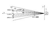
図3を用いて、前方の物体を検出し、検出した物体が頭上標識であるかどうかを演算部3により判定する手法について説明をする。本例では、自車両11の前方に走行車両12、さらに前方に頭上標識13がある場合について説明する。
【0036】
まず、レーザレーダ1は、レーザ光を出力し前方にある物体、走行車両12、頭上標識13を一次元的(x方向)にスキャニングする。レーザレーダ1は、物体から反射された反射レーザ光の光強度に基づいた反射信号を取得し、取得した反射信号に基づいた距離計測処理を行い距離計測情報を演算部3に送出する。
【0037】
走行車両12、頭上標識13に示されている複数の検出点からなる点列は、レーザレーダ1でスキャニングし、距離計測処理を行うことで算出された検出点を距離位置でプロットしたものである。
【0038】
演算部3は、レーザーレーダ1、車両挙動検出部2のそれぞれから出力された距離計測情報、車両走行情報に基づいて、複数の検出点をグルーピングして物体を示す検出点群を生成して物体検出処理を行う。
【0039】
演算部3は、検出点群に含まれる検出点のうち、隣接する検出点の距離差が1m程度であれば、同一反射物として検出点のグループ化を行う。演算部3は、車両挙動検出部2から出力された車両走行情報からこのグループ化した検出点群の相対速度を演算し、時系列的に位置や相対速度が同じであった場合、さらに検出点のグループ化を行って検出点群を物体として検出する。
【0040】
演算部3は、検出点群を物体として認識した後、検出点群の自車両11に対する相対速度に基づいて物体が走行車両か、停止物体かの判定をする。このとき、演算部3は、物体の自車両11に対する相対速度が所定のしきい値Vt1以上であれば走行車両とし、物体の自車両11に対する相対速度がしきい値Vt2以下であれば停止物体とする。なお、しきい値Vt1,Vt2は、予め設定されて演算部3内の図示しないメモリに格納された値である。これにより、図3における走行車両12は、演算部3によって走行車両として認識され、頭上標識13は停止物体として認識される。
【0041】
さらに、演算部3は、停止物体として認識した物体の計測点である左端点θl、中点θc、右端点θrのいずれかが走行車両の検出範囲内(角度)にあれば、頭上標識候補とする。これは、レーザレーダ1により一次元のスキャンを行った場合に、走行車両よりも高い位置に存在しなければ、角度的に停止物体と走行車両とはオーバーラップすることはないことによる。これにより、走行車両よりも高い位置でオーバーラップする停止物体は頭上標識の候補と判別する。
【0042】
図3では、停止物体として認識されている頭上標識13の検出点のうち右端検出点θrが、走行車両12の検出範囲内にあるため、頭上標識13は、頭上標識候補として演算部3に認識される。
【0043】
ただし、走行車両と停止車両とが距離計測の計測誤差によりオーバーラップする場合があり、この場合には、停止車両を頭上標識と誤判別させないために、走行車両の検出点の分散の程度がしきい値Nt1以上であるのみを停止物体を頭上標識候補とする。
【0044】
これは、走行車両と頭上標識とがオーバーラップする場合、オーバーラップする領域(スキャン範囲)では標識距離を示す検出点と車両距離を示す検出点とが混在するため、その角度における距離精度が悪くなり、走行車両検出領域内の検出点のばらつきが大きくなる。このため、走行車両の検出点のばらつきが大きければ(検出点分散がしきい値Nt1以上)、オーバーラップする停止物体を頭上標識候補とする。
【0045】
『距離データ充填率R』
次に図4を用いて、物体種別を判定するときに使用する上記各物体についての最大検出点数と、上記物体位置検出手段で検出された検出点数との割合を示す距離データ充填率Rについて説明をする。
【0046】
距離データ充填率Rは、nを検出点数、Zを距離、Wを物体幅、θをスキャン角度とすると、下記式(1)のように表すことができる。なお距離Zは、グルーピングした結果得た検出点群からなる物体と自車両11との距離を示しているが、物体の検出点は複数個あるため、各検出点に対する距離はそれぞれ多少のズレを含んでいる。したがって、ここで使用する距離Zは、検出距離の平均値又は中央値とする。
【0047】
R=(n×Z×tanθ)/W 式(1)
距離データ充填率Rは上記式(1)を用いて演算部3によって算出され、0〜1.0の数値をとる。例えば、物体幅Wに対応する検出範囲全てに検出点(距離データ)が存在すれば1.0となり、全てから検出点が得られない場合には1.0以下の値となる。標識の場合には、遠方からでも検出範囲の殆どから検出点が得られるため式(1)として示した距離データ充填率Rは1.0に近い値を示す。一方、遠方の車両では車両に備えられたリフレクタからのみ検出点が得られるため、距離データ充填率Rは小さい値となる。
【0048】
図4に示した物体幅Wの物体14において、例えば、得られる最大の検出点数は8個であり、物体14の検出点数nが7個であったとすると、距離データ充填率Rは0.875となり1.0近くになる。この場合、演算部3は物体14を標識であると判定する。また、物体14の検出点数nが2個であったとすると、距離データ充填率Rは0.25というように小さい値となり、この場合、演算部3は物体14を車両であると判定する。
【0049】
『停止物体の分類』
続いて、図5を用いて、停止物体として認識された物体を停止車両、大標識、小標識/デリニエイタのいずれかに分類する方法について説明をする。
【0050】
演算部3は、停止物体を停止車両、大標識、小標識/デリニエイタのいずれかに分類する際、グルーピングした検出点群についての相対速度V(例えば平均相対速度)、グルーピングした検出点群からなる物体幅W、グルーピングした検出点群からなる反射強度P(例えば平均反射強度)、距離データ充填率Rを用いる。
【0051】
演算部3は、物体の相対速度がしきい値Vt2以下で停止物体と認識した際に、以下に示す第1条件〜第4条件に基づいて、停止物体を停止車両、大標識、小標識/デリニエイタのいずれかに分類する。
【0052】
第1条件:停止車両に分類する条件は、物体幅Wが広く、距離データ充填率Rが小さいものを停止車両と分類する。なお、図5の停止物体16がこの条件に当てはまり、停止物体16を停止車両に分類する。
【0053】
第2条件:分類対象の手前に重なる物体が存在する場合は、大標識に分類する。なお、図5の停止物体17の手前に停止物体18が存在し、この条件に当てはまるため大標識に分類する。
【0054】
第3条件:物体幅Wが広く、距離データ充填率Rが大きい場合、大標識に分類する。
【0055】
第4条件:物体幅Wが狭い場合、小標識/デリニエイタに分類する。なお、図5では、停止物体15と、停止物体18がこの条件に相当し、小標識/デリニエイタに分類する。ただし、物体幅Wが広く、反射強度Pが弱いものについても、小標識/デリニエイタとする。また、反射強度Pが弱いものについては、判別の制度が落ちるため一旦判別後にも判別結果を見直すことが可能である小標識/デリニエイタに分類する。
【0056】
次に、演算部3は、上記第1条件〜第4条件で分類した検出点数がN個以上であれば、各検出点の分類結果の合計から、一番多い分類を物体種類の判定結果とする。上記第1条件〜第4条件で分類した検出点数がN個未満であれば、N個以上になるまで測定を継続させる。具体的には、図5に示す場合において、停止物体17を構成する検出点のうち、5個の検出点が上記第2条件又は第3条件により大標識に分類されたときには停止物体17の物体種別を大標識とする。
【0057】
演算部3は、小標識/デリニエイタに分類した停止物体について測定を継続し、判定結果を適時見直すこととする。その他に分類された停止物体については判定結果の見直しは実施しないこととする。
【0058】
『小標識/デリニエイタの判別見直し』
図6に、上述したように停止物体を分類する場合において、停止物体が小標識/デリニエイタに分類された検出点の判定結果を見直すときの処理を説明するための図を示す。
【0059】
例えば図6に示す停止物体19のように幅が広い物体では、自車両が走行して停止物体19との距離が次第に小さくなる場合、時間的に前では停止物体19の一部しかレーザレーダ1のスキャン範囲に存在しないために、小標識/デリニエイタに分類していても、距離が近づくにつれて物体全体がスキャン範囲内に存在するために小標識/デリニエイタには分類できない停止物体がある。
【0060】
このような場合に、停止物体19が完全にスキャン範囲に入っていない時間的に前の段階で小標識/デリニエイタに分類されたことは誤判定となる。したがって、演算部3は、小標識/デリニエイタと判別された物体に関して、このような誤判定を防止するために判定結果を見直す作業を実行する。演算部3による判定結果の見直しは、最初の判定と同様に検出データ数がN回以上のときに行い、判定結果が同じである場合には検出データ数をリセットする。
【0061】
『演算部3による物体種別判定処理手順』
続いて図7に示すフローチャートを用いて、物体種別判定装置による物体種別判定処理の手順について説明をする。
【0062】
ステップS1において、レーザレーダ1により自車両11の前方をスキャンすることで前方反射物からの信号を受信し、距離Zと反射強度Pとを含む検出点の計算してステップS2に処理を進める。
【0063】
ステップS2において、ステップS1で得た検出点において、隣接する検出点のうち距離差が小さいものを演算部3によりグループ化し、このグループ化した検出点群が時系列的に位置や相対速度が同じであればさらにグループ化を行う。演算部3によりグループ化処理を複数回実施することで、検出点群から構成される自車両11前方の物体存在を検出してステップS3に処理を進める。
【0064】
ステップS3において、演算部3によりステップS2で検出した各物体の相対速度から走行車両存在判定を行う。演算部3により相対速度がしきい値Vt1以上と判定したら処理をステップS4へと進め、相対速度がしきい値Vt1未満と判定したら処理をステップS5へと進める。
【0065】
ステップS4において、演算部3によりステップS2で検出された物体を構成する検出点群について、走行車両を構成する検出点であることを示す走行車両フラグを立てて、物体種別判定処理を終了する。
【0066】
一方、ステップS5において、演算部3によりステップS2でグループ化した検出点群の相対速度から停止物体の判定を行う。演算部3は、相対速度がしきい値Vt2以下であれば停止物体としてステップS6へと処理を進め、相対速度がしきい値Vt2より大きければ物体判定を行わず処理をステップS1へと戻す。
【0067】
ステップS6において、演算部3により頭上標識候補の抽出を行う。ステップS5において停止物体と判別された物体を構成する検出点のうち、の右端に位置する検出点、中心に位置する検出点、左端に位置する検出点のいずれかが自車両11に対して手前を走行する走行車両のスキャン範囲に存在する場合、当該物体を構成する検出点群を頭上標識候補としてステップS7に処理を進める。すなわち、演算部3により、自車両11からみて停止物体より手前に走行車両が存在し、自車両11からみて停止物体を検出したスキャン範囲と走行車両を検出したスキャン範囲とがオーバーラップするか否かの判定をして、オーバーラップするときにはステップS7に処理を進め、オーバーラップしないときにはステップS8に処理を進める。
【0068】
ステップS7において、演算部3により頭上標識の判定を行う。ステップS6で頭上標識候補とした物体を示す検出点群とスキャン範囲の角度的にオーバーラップする走行車両を示す検出点群の分散がしきい値Nt1以上であれば処理をステップS8に進め、分散がNt1未満であるときには頭上標識と判定せずに処理をステップS9に進める。
【0069】
ステップS8において、演算部3により、ステップS6で走行車両にオーバーラップしているとした停止物体を示す検出点群を頭上標識であると判定し、停止物体を構成する各検出点に頭上標識であることを示すフラグを立てて、物体種別判定処理を終了する。
【0070】
ステップS9において、演算部3により停止物体の種別を判定するために必要な特徴量の計算を行う。停止物体の種別を判定するための特徴量は検出点群の相対速度、物体幅W、反射強度P、距離データ充填率Rとする。反射強度Pは物体を構成する検出点群における最大強度Pとし、距離データ充填率Rは上述した式(1)から求める。演算部3は、特徴量を算出すると次のステップS10に処理を進める。
【0071】
ステップS10において、演算部3により、上記第1条件〜第4条件を適用することで求めた特徴量から停止物体を停止車両、大標識、小標識/デリニエイタのいずれかに分類してステップS11に処理を進める。
【0072】
ステップS11において、ステップS10で演算部3により分類された総検出点数が物体判定に必要な検出点数に達しているか否かの判定を行う。演算部3により総検出点数がN個以上であれば、次のステップS12に処理を進め、必要検出点数に達していなければ処理をステップS1へと戻す。
【0073】
ステップS12において、演算部3により物体判定を行う。停止車両、大標識、小標識/デリニエイタに分類された検出点数から、一番数の多いものを判定結果とし、次のステップS13に処理を進める。ただし、検出点数が同数の場合はステップS1以降の次回の処理に移る。また、演算部3は、停止物体が小標識/デリニエイタと判定され、上述した理由により再判定する場合には、蓄積された分類した結果をリセットする。
【0074】
ステップS13において、演算部3は物体判定の終了判定を行う。演算部3は、ステップS12で停止物体が小標識/デリニエイタ以外と判定された場合は物体判定を終了し、小標識/デリニエイタと判定された物体は再度ステップS1に戻って、再判定を行う。
【0075】
このようにして、物体種別判定装置は、自車両11の前方にある物体を検出し、さらに検出した物体が走行車両であるのか、頭上標識であるのか、小標識/デリニエイタであるのかという物体の種別を判定することができる。
【0076】
[実施形態の効果]
以上、詳細に説明したように、本実施形態に係る物体種別判定装置によれば、停止物体と自車両11との間にスキャン範囲の角度が重複して走行車両が存在する場合であっても、距離データ充填率Rに基づいて停止物体の種別を判定することができ、検出した物体を走行車両、停止物体とに的確に識別することができる。
【0077】
また、物体種別判定装置によれば、判定対象である停止物体と、自車両との間にある走行車両を示す検出点群のばらつきが大きい場合にのみ停止物体を頭上標識であると判定するので、停止物体と走行車両とがレーザレーダ1のスキャン範囲の角度的にオーバーラップする場合であっても、誤判定を防止することができる。
【0078】
更に、物体種別判定装置によれば、停止物体を示す検出点群の相対速度、幅、反射強度、距離データ充填率Rに基づいて、停止車両、大標識、小標識/デリニエイタのいずれかの種別に分類する判定をするので、前方の停止物が普通車や大型トラックの幅と同等な標識であっても確実に標識と車両との区別をすることができる。
【0079】
更にまた、物体種別判定装置によれば、スキャン範囲内に他の物体が存在しない場合に停止物体を停止車両と判定し、スキャン範囲内に他の物体が存在する場合に停止物体を大標識と判定するので、標識の自車両11に対する手前に物体が存在する場合には標識の一部の検出点が手前の物体により検出することができない場合があり、距離データ充填率Rが停止車両の判定条件に一致する場合に対応することができる。したがって、この物体種別判定装置によれば、手前に物体が存在する停止物体に対しては大標識とすることにより停止車両の誤判定を防止することができる。
【0080】
更にまた、物体種別判定装置によれば、停止物体が小標識/デリニエイタであると判定された場合、判定処理を判定処理回数が所定の回数となるまで継続させて判定結果を見直すので、物体の一部がスキャン範囲に存在する場合には、物体幅が狭く小標識/デリニエイタと判定されるが、時間が経過して物体の完全にスキャン範囲内に存在する場合には誤判定となることを防止することができる。したがって、この物体種別判定装置によれば、小標識/デリニエイタと判定した物体については分類の決定を再度見直すことにより誤判定を防止することができる。
【0081】
なお、上述の実施の形態は本発明の一例である。このため、本発明は、上述の実施形態に限定されることはなく、この実施の形態以外であっても、本発明に係る技術的思想を逸脱しない範囲であれば、設計等に応じて種々の変更が可能であることは勿論である。
【図面の簡単な説明】
【図1】本発明を適用した物体種別判定装置の機能的な構成を示すブロック図である。
【図2】レーザレーダを自車両の前方部分に搭載したときのレーザ光の光軸を説明するための側面図(a)及び上面図(b)である。
【図3】演算部により頭上標識を検出する際の処理内容について説明するための図である。
【図4】演算部により算出される距離データ充填率について説明するための図である。
【図5】演算部により検出された停止物体を3つの種別に分類する際の処理内容について説明するための図である。
【図6】演算部により小標識/デリニエイタに分類された停止物体を再判定する処理内容について説明するための図である。
【図7】本発明を適用した物体種別判定装置により自車両の前方の物体の種別を判定する際の処理手順について説明するためのフローチャートである。
【符号の説明】
1 レーザレーダ
2 車両挙動検出部
3 演算部
11 自車両[0001]
BACKGROUND OF THE INVENTION
The present invention detects the presence or absence of an object from a reflected wave from an object mounted on a vehicle and emits invisible laser light or radio waves, and discriminates a traveling vehicle, a sign, and the like from the detected object. The present invention relates to an object type determination device and an object type determination method.
[0002]
[Prior art]
Conventionally, as a target determination device that determines the type of an object using a radar, for example, there is a control target selection device disclosed in Japanese Patent Laid-Open No. 2000-132799.
[0003]
This control object sorting device includes a distance measuring unit, and first generates a detection group by collecting a plurality of distance groups according to data measured by the distance measuring unit.
[0004]
The control object sorting device performs detection group generation for each distance measurement, further groups the detection groups according to the position and movement of each detection group, and recognizes them as one object.
[0005]
Then, the control object sorting device determines whether the recognized object is a preceding vehicle, a delineator, or a sign depending on the movement and the width of the object.
[0006]
[Problems to be solved by the invention]
A control target selection device that is a target determination device that determines a type of a conventional object determines the type of the object based on information such as the position and movement of the detected object and the width of the object.
[0007]
However, in the determination of the type of object by such a method, for example, when there is no vehicle traveling ahead of the host vehicle, a guide sign displaying a destination etc. on a distant head on the expressway is from the vehicle Since it is obviously large, it is not determined that the vehicle is a stopped vehicle, but it is very difficult to determine whether a sign that is equivalent to a normal vehicle or a heavy truck is a stopped vehicle or a sign.
[0008]
Therefore, in the conventional method, there is a problem that a stop object in front of the own lane cannot be distinguished from a vehicle and a sign.
[0009]
The present invention has been proposed in view of the above-described circumstances, and provides an object type determination device and an object type determination method that can accurately identify a detected object as a traveling vehicle and a stopped object. .
[0010]
[Means for Solving the Problems]
In order to solve the above-described problem, the invention according to
[0011]
In the invention according to
(N × Z × tan θ) / W
Calculation is performed using the expression expressed by.
[0012]
In the invention according to
[0013]
According to a fourth aspect of the present invention, the third determination means includes a stop vehicle, a large sign, a small sign / deliminator based on the relative speed, width, reflection intensity, and data filling rate of the detection point group indicating the stop object. It is determined to be classified into one of the types.
[0014]
In the invention according to
[0015]
In the invention according to claim 6, when it is determined that the stop object is a small sign / deliminator, the third determination unit continues the determination process until the number of determination processes reaches a predetermined number.
[0016]
In the invention which concerns on Claim 7, in order to solve the above-mentioned subject, the object classification determination which determines the classification of the object which is mounted in the own vehicle and exists in front of the own vehicle Method A plurality of detections indicating the position of the object with respect to the host vehicle based on the detected reflected wave by detecting a reflected wave reflected from the object by scanning the object existing in front of the host vehicle with a transmission wave. A point is generated, a relative speed of the object existing in front of the host vehicle with respect to the host vehicle is detected for each detection point, and a grouping process based on the object position of each detection point and the relative speed of each detection point is performed. And detecting the object composed of detection point groups of a plurality of detection points, and determining whether the object is a traveling vehicle or a stopped object based on the relative speed of the detection point group indicating the object. If it is determined that the object is a stop object and a traveling vehicle exists between the stop object and the host vehicle, the stop object is determined to be an overhead sign, and maximum detection for each object is performed. The number of points and the above detection points If the object is determined to be a stop object based on the relative speed and there is no traveling vehicle between the stop object and the host vehicle, at least the calculated data is calculated. Based on the filling rate, the stop object is determined as one of a stop vehicle, a large sign, and a small sign / deliniator.
[0017]
【The invention's effect】
According to the first aspect of the present invention, the type of the stopped object is determined based on the data filling rate even when the traveling vehicle exists with the angle of the scan range overlapping between the stopped object and the host vehicle. The detected object can be accurately identified as the traveling vehicle and the stopped object.
[0018]
According to the second aspect of the present invention, the arithmetic expression using the number n of detection points, the average value Z of the distances between the detection points and the own vehicle, the end width W of the detection points indicating the object, and the angle θ for scanning the object The data filling rate can be used to determine the type of the stopped object, and the detected object can be accurately identified as the traveling vehicle and the stopped object, as in the first aspect of the invention. Can do.
[0019]
According to the invention of
[0020]
According to the fourth aspect of the present invention, any one of the stop vehicle, the large sign, and the small sign / delineator is determined based on the relative speed, width, reflection intensity, and data filling rate of the detection point group indicating the stopped object by the third determination unit. Therefore, even if the front stop is a sign equivalent to the width of a normal car or a large truck, it is possible to reliably distinguish the sign from the vehicle.
[0021]
According to the fifth aspect of the present invention, the third determining means determines that the stopped object is a stopped vehicle when no other object exists within the scanning range, and the stopped object when the other object exists within the scanning range. Therefore, if there is an object in front of the sign's own vehicle, some detection points of the sign may not be detected by the object in front, and the data filling rate is It is possible to cope with a case where the determination condition is met. Therefore, it is possible to prevent erroneous determination of a stopped vehicle by using a large sign for a stopped object with an object in front.
[0022]
According to the sixth aspect of the present invention, when the third determination unit determines that the stopped object is the small sign / deliminator, the determination process is continued until the determination process count reaches a predetermined number, and the determination result is reviewed. If a part of the object exists in the scanning range, the object width is narrow and it is determined to be a small sign / deliniator. It is possible to prevent erroneous determination. Accordingly, it is possible to prevent erroneous determination by reviewing the classification determination for the object determined as the small mark / deliniator.
[0023]
According to the seventh aspect of the present invention, the type of the stopped object is determined based on the data filling rate even when the traveling vehicle exists with the angle of the scan range overlapping between the stopped object and the host vehicle. The detected object can be accurately identified as the traveling vehicle and the stopped object.
[0024]
DETAILED DESCRIPTION OF THE INVENTION
Hereinafter, embodiments of the present invention will be described with reference to the drawings.
[0025]
The present invention is applied, for example, to the object type determination apparatus shown in FIG.
[0026]
[Configuration of Object Type Determination Device]
FIG. 1 is a block diagram illustrating a functional configuration of an object type determination device mounted on a vehicle. This object type determination device includes a
[0027]
The object type determination process is, for example, a process of determining a preceding traveling vehicle that travels ahead of the host vehicle and a stop object, and further determining whether the stop object is an overhead sign in front of the host vehicle. . By performing this object type determination process, a preceding traveling vehicle and a stopped object existing in front of the host vehicle are presented to the driver of the host vehicle.
[0028]
As shown in the side view of FIG. 2A and the top view of FIG. 2B, the
[0029]
The
[0030]
The
[0031]
The vehicle
[0032]
The vehicle
[0033]
The
[0034]
Based on information from the
[0035]
[Operation of Calculation Unit 3]
"Detection of overhead signs"
A method of detecting a front object and determining whether the detected object is an overhead sign by the
[0036]
First, the
[0037]
The point sequence composed of a plurality of detection points shown on the traveling
[0038]
Based on the distance measurement information and vehicle travel information output from the
[0039]
If the distance difference between adjacent detection points is about 1 m among the detection points included in the detection point group, the
[0040]
After recognizing the detection point group as an object, the
[0041]
Further, if any of the left end point θl, the midpoint θc, and the right end point θr, which are measurement points of the object recognized as a stopped object, is within the detection range (angle) of the traveling vehicle, the
[0042]
In FIG. 3, the right end detection point θr among the detection points of the
[0043]
However, the traveling vehicle and the stopped vehicle may overlap due to a measurement error in distance measurement.In this case, in order not to misidentify the stopped vehicle as an overhead sign, the degree of dispersion of the detection points of the traveling vehicle is reduced. Only the threshold value Nt1 or more is set as the stop sign candidate for the overhead object.
[0044]
This is because, when the traveling vehicle and the overhead sign overlap, detection points indicating the sign distance and detection points indicating the vehicle distance are mixed in the overlapping region (scan range), so the distance accuracy at the angle is poor. Thus, the variation of the detection points in the traveling vehicle detection area becomes large. For this reason, if the variation of the detection points of a traveling vehicle is large (detection point dispersion | distribution is more than threshold value Nt1), the stop object which overlaps will be made into an overhead sign candidate.
[0045]
"Distance data filling rate R"
Next, a distance data filling rate R indicating the ratio between the maximum number of detected points for each object used for determining the object type and the number of detected points detected by the object position detecting means will be described with reference to FIG. do.
[0046]
The distance data filling rate R can be expressed by the following equation (1), where n is the number of detection points, Z is the distance, W is the object width, and θ is the scan angle. The distance Z indicates the distance between the object consisting of a group of detection points obtained as a result of grouping and the
[0047]
R = (n × Z × tan θ) / W Formula (1)
The distance data filling rate R is calculated by the
[0048]
In the
[0049]
"Classification of stationary objects"
Next, a method for classifying an object recognized as a stop object into one of a stop vehicle, a large sign, and a small sign / deliniator will be described with reference to FIG.
[0050]
The
[0051]
When the
[0052]
First condition: As a condition for classifying as a stopped vehicle, a vehicle having a wide object width W and a small distance data filling rate R is classified as a stopped vehicle. Note that the stopped
[0053]
Second condition: If there is an overlapping object in front of the classification target, it is classified as a large sign. In addition, the
[0054]
Third condition: When the object width W is wide and the distance data filling rate R is large, it is classified as a large marker.
[0055]
Fourth condition: When the object width W is narrow, it is classified into a small marker / deliniator. In FIG. 5, the
[0056]
Next, when the number of detection points classified by the first condition to the fourth condition is N or more, the
[0057]
The
[0058]
“Small signs / Deliminator discrimination review”
FIG. 6 is a diagram for explaining the processing when reviewing the determination result of the detection point where the stop object is classified into the small mark / delineator when the stop object is classified as described above.
[0059]
For example, in the case of a wide object such as the
[0060]
In such a case, it is erroneously determined that the
[0061]
"Object type determination processing procedure by the
Subsequently, the procedure of the object type determination process by the object type determination device will be described using the flowchart shown in FIG.
[0062]
In step S1, the
[0063]
In step S2, the detection points obtained in step S1 are grouped by the
[0064]
In step S3, the traveling vehicle presence determination is performed from the relative speed of each object detected in step S2 by the
[0065]
In step S4, with respect to the detection point group constituting the object detected in step S2 by the
[0066]
On the other hand, in step S5, the calculating
[0067]
In step S6, the overhead marker candidate is extracted by the
[0068]
In step S <b> 7, the overhead mark is determined by the
[0069]
In step S8, the
[0070]
In step S <b> 9, the feature amount necessary for determining the type of the stopped object is calculated by the
[0071]
In step S10, the
[0072]
In step S11, it is determined whether or not the total number of detection points classified by the
[0073]
In step S12, the
[0074]
In step S <b> 13, the
[0075]
In this way, the object type determination device detects an object in front of the
[0076]
[Effect of the embodiment]
As described above in detail, according to the object type determination device according to the present embodiment, even when the traveling vehicle exists with the angle of the scan range overlapping between the stopped object and the
[0077]
Further, according to the object type determination device, the stop object is determined to be an overhead sign only when there is a large variation in the detection point group indicating the traveling vehicle between the stop object to be determined and the host vehicle. Even when the stopped object and the traveling vehicle overlap in the angular range of the scan range of the
[0078]
Further, according to the object type determination device, based on the relative speed, width, reflection intensity, and distance data filling rate R of the detection point group indicating the stop object, any type of stop vehicle, large sign, and small sign / deliminator Therefore, even if the front stop is a sign equivalent to the width of a normal car or a large truck, it is possible to reliably distinguish the sign from the vehicle.
[0079]
Furthermore, according to the object type determination device, when there is no other object in the scan range, the stop object is determined as a stop vehicle, and when there is another object in the scan range, the stop object is Therefore, when an object is present in front of the sign's
[0080]
Furthermore, according to the object type determination device, when it is determined that the stopped object is a small sign / delineator, the determination process is continued until the predetermined number of determination processes is performed, so that the determination result is reviewed. If a part of the object is in the scan range, the object width is narrow and it is determined to be a small sign / deliniator. Can be prevented. Therefore, according to this object type determination apparatus, it is possible to prevent erroneous determination by reviewing the classification determination again for an object determined to be a small sign / delineator.
[0081]
The above-described embodiment is an example of the present invention. For this reason, the present invention is not limited to the above-described embodiment, and various modifications can be made depending on the design and the like as long as the technical idea according to the present invention is not deviated from this embodiment. Of course, it is possible to change.
[Brief description of the drawings]
FIG. 1 is a block diagram showing a functional configuration of an object type determination apparatus to which the present invention is applied.
FIGS. 2A and 2B are a side view and a top view for explaining an optical axis of laser light when a laser radar is mounted on a front portion of the host vehicle.
FIG. 3 is a diagram for explaining processing contents when an overhead marker is detected by a calculation unit;
FIG. 4 is a diagram for explaining a distance data filling rate calculated by a calculation unit.
FIG. 5 is a diagram for explaining processing contents when classifying stopped objects detected by a calculation unit into three types;
FIG. 6 is a diagram for explaining processing contents for re-determining a stopped object classified as a small marker / delineator by a calculation unit;
FIG. 7 is a flowchart for explaining a processing procedure when an object type determination device to which the present invention is applied determines an object type ahead of the host vehicle.
[Explanation of symbols]
1 Laser radar
2 Vehicle behavior detector
3 Calculation unit
11 Own vehicle
Claims (7)
自車両前方に存在する上記物体に送信波を走査させ、上記物体から反射される反射波を検出し、検出した反射波に基づいて、上記自車両に対する物体位置を示す複数の検出点を生成する物体位置検出手段と、
自車両前方に存在する上記物体の自車両に対する相対速度を上記物体位置検出手段で検出された各検出点ごとに検出する相対速度検出手段と、
上記物体位置検出手段により生成した各検出点の物体位置、及び上記相対速度検出手段で検出した各検出点の相対速度に基づくグループ化処理を行って、複数の検出点の検出点群からなる上記物体を検出する物体検出手段と、
上記物体検出手段で検出された物体を示す検出点群の相対速度に基づいて、上記物体が走行車両であるのか、停止物体であるのかの判定をする第1判定手段と、
上記第1判定手段によって上記物体が停止物体であると判定され、上記停止物体と、自車両との間に走行車両が存在する場合、上記停止物体を頭上標識であると判定する第2判定手段と、
上記各物体についての最大検出点数と、上記物体位置検出手段で検出された検出点数との割合を示すデータ充填率を算出する演算手段と、
上記第1判定手段によって上記物体が停止物体であると判定され、上記停止物体と、自車両との間に走行車両が存在しない場合、上記演算手段によって算出されたデータ充填率に基づいて上記停止物体の種別を判定する第3判定手段と
を備えることを特徴とする物体種別判定装置。An object type determination device that determines the type of an object that is mounted on the host vehicle and exists in front of the host vehicle,
Scan the transmitted wave on the object existing in front of the host vehicle, detect the reflected wave reflected from the object, and generate a plurality of detection points indicating the object position with respect to the host vehicle based on the detected reflected wave. Object position detection means;
A relative speed detecting means for detecting a relative speed of the object existing ahead of the own vehicle with respect to the own vehicle for each detection point detected by the object position detecting means;
A grouping process based on the object position of each detection point generated by the object position detection unit and the relative speed of each detection point detected by the relative speed detection unit is performed, and the detection point group including a plurality of detection point groups An object detection means for detecting an object;
First determination means for determining whether the object is a traveling vehicle or a stop object based on a relative speed of a detection point group indicating the object detected by the object detection means;
Second determination means for determining that the stop object is an overhead sign when the first determination means determines that the object is a stop object and a traveling vehicle exists between the stop object and the host vehicle. When,
Arithmetic means for calculating a data filling rate indicating a ratio between the maximum number of detected points for each object and the number of detected points detected by the object position detecting means;
When the first determination means determines that the object is a stop object and no traveling vehicle exists between the stop object and the host vehicle, the stop is performed based on the data filling rate calculated by the calculation means. An object type determination apparatus comprising: third determination means for determining an object type.
(n×Z×tanθ)/W
で表現される式を用いて演算することを特徴とする請求項1記載の物体種別判定装置。The calculation means is such that the number of detection points is n, the average value of the distances between the detection points and the host vehicle is Z, the end width of the detection points indicating the object is W, and the angle at which the object position detection means scans the object Is set to (n × Z × tan θ) / W
The object type determination apparatus according to claim 1, wherein the calculation is performed using an expression expressed by:
を特徴とする請求項1記載の物体種別判定装置。The second determination means determines that the stop object is an overhead sign only when there is a large variation in the detection point group indicating the traveling vehicle between the stop object to be determined and the host vehicle. The object type determination apparatus according to claim 1.
を特徴とする請求項1記載の物体種別判定装置。The third determination means classifies the detection point group into one of the types of a stop vehicle, a large sign, and a small sign / deliminator based on the relative speed, width, reflection intensity, and data filling rate of the detection point group indicating the stop object. The object type determination apparatus according to claim 1, wherein the determination is performed.
を特徴とする請求項4記載の物体種別判定装置。The third determining unit determines that the stopped object is a stopped vehicle when there is no other object within the scanning range of the object position detecting unit, and the stopped object when there is another object within the scanning range. The object type determination apparatus according to claim 4, wherein the object type is determined as a large sign.
を特徴とする請求項4記載の物体種別判定装置。5. The object type according to claim 4, wherein, when it is determined that the stop object is a small sign / deliminator, the third determination unit continues the determination process until the number of determination processes reaches a predetermined number. Judgment device.
自車両前方に存在する上記物体に送信波を走査させ、上記物体から反射される反射波を検出し、検出した反射波に基づいて、上記自車両に対する物体位置を示す複数の検出点を生成すると共に、自車両前方に存在する上記物体の自車両に対する相対速度を各検出点ごとに検出し、
上記各検出点の物体位置、及び各検出点の相対速度に基づくグループ化処理を行って、複数の検出点の検出点群からなる上記物体を検出し、
上記物体を示す検出点群の相対速度に基づいて、上記物体が走行車両であるのか、停止物体であるのかの判定をし、
上記物体が停止物体であると判定され、上記停止物体と、自車両との間に走行車両が存在する場合、上記停止物体を頭上標識であると判定し、
上記各物体についての最大検出点数と、上記検出点数との割合を示すデータ充填率を算出し、
上記物体が相対速度に基づいて停止物体であると判定され、上記停止物体と上記自車両との間に走行車両がない場合、少なくとも上記算出されたデータ充填率に基づいて上記停止物体を停止車両、大標識、小標識/デリニエイタのいずれかの種別に判定すること
を特徴とする物体種別判定方法。An object type determination method for determining the type of an object mounted on the host vehicle and existing in front of the host vehicle,
Scan the transmitted wave on the object existing in front of the host vehicle, detect the reflected wave reflected from the object, and generate a plurality of detection points indicating the object position with respect to the host vehicle based on the detected reflected wave. In addition, the relative speed of the object existing in front of the host vehicle with respect to the host vehicle is detected for each detection point,
Perform a grouping process based on the object position of each detection point and the relative speed of each detection point to detect the object composed of a plurality of detection point groups of detection points,
Based on the relative speed of the detection point group indicating the object, determine whether the object is a traveling vehicle or a stopped object,
When it is determined that the object is a stop object, and there is a traveling vehicle between the stop object and the host vehicle, the stop object is determined to be an overhead sign,
Calculate the data filling rate indicating the ratio between the maximum number of detected points for each object and the number of detected points,
When it is determined that the object is a stopped object based on the relative speed and there is no traveling vehicle between the stopped object and the host vehicle, the stopped object is stopped based on at least the calculated data filling rate. An object type determining method, characterized in that the type is determined as one of a large sign and a small sign / deliniator.
Priority Applications (1)
| Application Number | Priority Date | Filing Date | Title |
|---|---|---|---|
| JP2001203514A JP3664110B2 (en) | 2001-07-04 | 2001-07-04 | Object type determination device and object type determination method |
Applications Claiming Priority (1)
| Application Number | Priority Date | Filing Date | Title |
|---|---|---|---|
| JP2001203514A JP3664110B2 (en) | 2001-07-04 | 2001-07-04 | Object type determination device and object type determination method |
Publications (2)
| Publication Number | Publication Date |
|---|---|
| JP2003014844A JP2003014844A (en) | 2003-01-15 |
| JP3664110B2 true JP3664110B2 (en) | 2005-06-22 |
Family
ID=19040131
Family Applications (1)
| Application Number | Title | Priority Date | Filing Date |
|---|---|---|---|
| JP2001203514A Expired - Fee Related JP3664110B2 (en) | 2001-07-04 | 2001-07-04 | Object type determination device and object type determination method |
Country Status (1)
| Country | Link |
|---|---|
| JP (1) | JP3664110B2 (en) |
Families Citing this family (13)
| Publication number | Priority date | Publication date | Assignee | Title |
|---|---|---|---|---|
| JP3664127B2 (en) * | 2001-06-07 | 2005-06-22 | 日産自動車株式会社 | Object detection device |
| JP2005173917A (en) * | 2003-12-10 | 2005-06-30 | Nissan Motor Co Ltd | Device and method for detecting branching path |
| JP3941795B2 (en) * | 2004-04-28 | 2007-07-04 | 株式会社デンソー | Leading vehicle recognition device |
| JP2006258497A (en) * | 2005-03-15 | 2006-09-28 | Omron Corp | Object recognition apparatus for vehicle |
| JP2009288098A (en) * | 2008-05-29 | 2009-12-10 | Omron Corp | Physical object detector |
| KR101292606B1 (en) * | 2008-08-22 | 2013-08-05 | 주식회사 만도 | Cruise control apparatus and method thereof |
| JP2010181246A (en) * | 2009-02-05 | 2010-08-19 | Daihatsu Motor Co Ltd | Body recognizer |
| JP5866682B2 (en) * | 2011-09-20 | 2016-02-17 | 株式会社国際電気通信基礎技術研究所 | Measuring system and measuring method |
| US10500954B2 (en) * | 2012-05-03 | 2019-12-10 | Daniel McNicholas | Compressed natural gas vehicle safety system and method |
| US10040680B2 (en) | 2012-05-03 | 2018-08-07 | Daniel McNicholas | Compressed natural gas vehicle safety system and method |
| WO2014168851A1 (en) * | 2013-04-11 | 2014-10-16 | Google Inc. | Methods and systems for detecting weather conditions using vehicle onboard sensors |
| JP2016197018A (en) * | 2015-04-02 | 2016-11-24 | 株式会社デンソー | Collision avoidance assist device |
| JP6523196B2 (en) * | 2016-03-17 | 2019-05-29 | 株式会社東芝 | Estimation apparatus, method and program |
-
2001
- 2001-07-04 JP JP2001203514A patent/JP3664110B2/en not_active Expired - Fee Related
Also Published As
| Publication number | Publication date |
|---|---|
| JP2003014844A (en) | 2003-01-15 |
Similar Documents
| Publication | Publication Date | Title |
|---|---|---|
| JP3427809B2 (en) | Vehicle road shape recognition method and apparatus, recording medium | |
| JP3947193B2 (en) | Vehicle course prediction method and apparatus | |
| JP3664110B2 (en) | Object type determination device and object type determination method | |
| JP3684776B2 (en) | Obstacle recognition device for vehicles | |
| JP3664127B2 (en) | Object detection device | |
| JP6970936B2 (en) | Object detector, object detection program, and recording medium | |
| JP3690366B2 (en) | Front object detection device | |
| US10732263B2 (en) | Method for classifying a longitudinally extended stationary object in a lateral surrounding area of a motor vehicle, driver assistance system and motor vehicle | |
| JPH0875848A (en) | Method and device for tracking body | |
| JP3427817B2 (en) | Vehicle obstacle recognition method and apparatus, recording medium | |
| JP2021513643A (en) | Methods and devices for detecting critical lateral movements | |
| JP3341186B2 (en) | Object discriminating apparatus and method, and vehicle equipped with object discriminating apparatus | |
| Shimomura et al. | An algorithm for distinguishing the types of objects on the road using laser radar and vision | |
| JP2012242935A (en) | Vehicular road shape recognition method and device, and recording medium | |
| WO2015025673A1 (en) | Axle detection device | |
| JP2004271513A (en) | Device for detecting forward object and method for detecting forward object | |
| US20210364280A1 (en) | Road surface area detection device, road surface area detection system, vehicle, and road surface area detection method | |
| RU2722465C1 (en) | Vehicle tire recognition device and method | |
| JP2004020492A (en) | Front object recognition device | |
| JP3653862B2 (en) | Vehicle curve diameter estimation device and target preceding vehicle detection device | |
| JP3399104B2 (en) | Leading vehicle detection device and approach warning device | |
| JP3229226B2 (en) | Leading vehicle recognition device and recognition method | |
| JP3287166B2 (en) | Distance measuring device | |
| JP2012242937A (en) | Vehicular road shape recognition method and device, and recording medium | |
| JPH11144198A (en) | Object identifying device for vehicle |
Legal Events
| Date | Code | Title | Description |
|---|---|---|---|
| A977 | Report on retrieval |
Free format text: JAPANESE INTERMEDIATE CODE: A971007 Effective date: 20040929 |
|
| A131 | Notification of reasons for refusal |
Free format text: JAPANESE INTERMEDIATE CODE: A131 Effective date: 20041026 |
|
| A521 | Written amendment |
Free format text: JAPANESE INTERMEDIATE CODE: A523 Effective date: 20041207 |
|
| TRDD | Decision of grant or rejection written | ||
| A01 | Written decision to grant a patent or to grant a registration (utility model) |
Free format text: JAPANESE INTERMEDIATE CODE: A01 Effective date: 20050308 |
|
| A61 | First payment of annual fees (during grant procedure) |
Free format text: JAPANESE INTERMEDIATE CODE: A61 Effective date: 20050321 |
|
| R150 | Certificate of patent or registration of utility model |
Free format text: JAPANESE INTERMEDIATE CODE: R150 |
|
| FPAY | Renewal fee payment (event date is renewal date of database) |
Free format text: PAYMENT UNTIL: 20090408 Year of fee payment: 4 |
|
| FPAY | Renewal fee payment (event date is renewal date of database) |
Free format text: PAYMENT UNTIL: 20090408 Year of fee payment: 4 |
|
| FPAY | Renewal fee payment (event date is renewal date of database) |
Free format text: PAYMENT UNTIL: 20100408 Year of fee payment: 5 |
|
| FPAY | Renewal fee payment (event date is renewal date of database) |
Free format text: PAYMENT UNTIL: 20110408 Year of fee payment: 6 |
|
| FPAY | Renewal fee payment (event date is renewal date of database) |
Free format text: PAYMENT UNTIL: 20120408 Year of fee payment: 7 |
|
| FPAY | Renewal fee payment (event date is renewal date of database) |
Free format text: PAYMENT UNTIL: 20130408 Year of fee payment: 8 |
|
| LAPS | Cancellation because of no payment of annual fees |