JP3663712B2 - Dental air turbine handpiece - Google Patents
Dental air turbine handpiece Download PDFInfo
- Publication number
- JP3663712B2 JP3663712B2 JP01384896A JP1384896A JP3663712B2 JP 3663712 B2 JP3663712 B2 JP 3663712B2 JP 01384896 A JP01384896 A JP 01384896A JP 1384896 A JP1384896 A JP 1384896A JP 3663712 B2 JP3663712 B2 JP 3663712B2
- Authority
- JP
- Japan
- Prior art keywords
- air
- air supply
- chamber
- turbine
- turbine blade
- Prior art date
- Legal status (The legal status is an assumption and is not a legal conclusion. Google has not performed a legal analysis and makes no representation as to the accuracy of the status listed.)
- Expired - Fee Related
Links
Images


Description
【0001】
【発明の属する技術分野】
本発明は、医療用の歯科用エアータービンハンドピースに係わり、特に切削工具を回転させるトルクの増大を図った歯科用エアータービンハンドピースに関する。
【0002】
【従来の技術と発明が解決しようとする課題】
従来の歯科用エアータービンハンドピースにおいては、歯科治療の施術時例えば患者の歯牙に穿孔する際、切削工具の回転にかなりの負荷がかかった場合トルクが減衰し、回転速度が低下することがあった。
【0003】
【課題を解決するための手段】
本発明者は、種々検討の結果、下記の構成により上記課題を解決した。
(1)ハウジング内に切削工具を保持するための回転軸に固定されたタービン翼と、タービン翼回転用のエアーを流す給気路及びタービン翼回転後のエアーを排出する排気路とを備える歯科用エアータービンハンドピースにおいて、前記給気路先端の給気口の口径に対し、排気路の入口端の排気口の口径を大きく設定し、かつ、上記給気口から排気口に至るハウジング内を周回するエアー通路を、給気口から排気口側にかけて順次拡大させ形成させたことを特徴とする歯科用エアータービンハンドピース。
(2)タービン翼とチャンバーの上下内壁面の間隙を狭くとって配設したことを特徴とする前記(1)項に記載の歯科用エアータービンハンドピース。
(3)ヘッド部及びネック部が合成樹脂で形成されていることを特徴とする(1)項又は(2)項に記載の歯科用エアータービンハンドピース。
【0004】
【発明の実施の形態】
以下に本発明の実施の形態を、図面に基づいて説明する。
図1は本発明の歯科用エアータービンハンドピースのヘッド部とネック部の縦断面図である。
図において、1はヘッド部、2はネック部、3はヘッドハウジング、4はキヤップ部、5はネック部本体、7はチャンバー、8はタービン翼、9は給気路、10は排気路、11は軸受部、12は回転軸、13は切削工具、14は内輪、15は外輪、16はボール、17はリテーナー、18はOリング、19はウエーブワッシャー、30は上下空隙、31は左右空隙、91は給気口である。
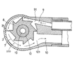
図2は図1のA−A’断面図でタービン翼と加圧空気の流路図である。
図において、100はエアー通路、101は排気口である。
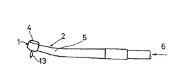
図3は本発明の歯科用エアータービンハンドピースの外観図である。
図において、6はエアー供給部である。
【0005】
図4は従来の歯科用エアータービンハンドピースのヘッド部とネック部の縦断面図である。
図において、1’はヘッド部、2’はネック部、3’はヘッドハウジング、4’はキヤップ部、7’はチャンバー、8’はタービン翼、30’は上下空隙、31’は左右空隙である。
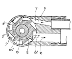
図5は図4のA−A’断面図でタービン翼と加圧空気の流路図である。
図において、100’はエアー通路、101’は排気口である。
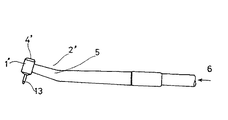
図6は従来の歯科用エアータービンハンドピースの外観図である。
図において、6はエアー供給部である。
【0006】
先ず従来の歯科用エアータービンハンドピースの構造について説明する。
図4に示すようにヘッド部1’は、チャンバー7’内に周縁部にタービン翼8’を有する回転軸12を配置し、ヘッド部1’の内部に前記回転軸12を回転自在に軸受部11を介して支承している。また、前記ヘッド部1’はヘッドハウジング3’とキヤップ部4’よりなり、そして前記タービン翼8’を配置するためのチャンバー7’が形成されると共に、前記回転軸12を回転自在に支承するための軸受部11が配設されている。さらに回転軸12の軸心部には歯科用の切削工具13の軸が固定保持される。
軸受部12は、内輪14、外輪15、ボール16及びリテーナー17からなるボールベアリングより構成され、また、ボールベアリングの外周側部には、求軸芯のためのOリング18や、支承用のウエーブワッシャー19が配設されている。
そして、タービン翼8’は回転軸12の軸方向にみて、タービン翼8’とチャンバー7’の上下内壁面の上下間隙30’は広くとり、左右内壁面31’との左右間隙31’は狭くとって配設されている。
前記ネック部2’は、ネック部本体5がチャンバー7’内に配設されたタービン翼8’に加圧空気を供給するための給気路9と、給気口91及びチャンバー7’内の加圧空気を排気するための排気路10’と排気口101’によって構成される。
【0007】
次に従来の歯科用エアータービンハンドピースの作用について説明する。
図4に示すように、前記加圧空気をネック部2’のネック部本体5に配設された給気路9に給気し、該加圧空気を給気口91を通してチャンバー7’内に導きタービン翼8’に噴射させ、回転軸12に回転駆動力を発生させた後、チャンバー7’内から加圧空気を排気口101’を通って排気路10に排気することにより行われている。
図5に示すように、上記の作用における加圧空気の流れは、チャンバー7’内を回転軸12を中心として、エアー通路100’の実線矢印と点線矢印の方向に周回しながらUターンして排気口101’を通って排気路10に排気される。
【0008】
上記の構成の歯科用エアータービンハンドピースにおいて、回転軸12のトルクを増大するには、理論的には加圧空気による給気口91での給気速度を速くするか、加圧空気の単位時間当たりの給気量を増大させればよいが、歯科用エアータービンハンドピースは患者の口腔内に挿入し施術するため、ヘッドの大きさの制約と、排気は直接口腔内にはできない制約がある。このため、実際には
▲1▼給気速度を増大させようとして加圧空気圧を増大させても、周知のように給気速度を音速以上に増大することができないので、回転軸12のトルクの増大には限界がある。
▲2▼給気量を増大させようとして加圧空気圧を増大させても、
1)給気量の増大により前述した構造のチャンバー7’内の圧力が上昇し、その結果、給気速度を低下させる。
2)給気された加圧空気は、タービン翼8’に衝突した後、回転軸12と同方向に主としてタービン翼8’の上下間隙30’(図4)を通って図5に示す点線矢印のようにチャンバー7’内を周回するが、回転軸12の回転速度に比較して周回速度は遅いので、チャンバー7’内で抵抗体として作用し、その量も増加する。
▲3▼給気量を増大させようとして給気口91の断面積を増大させても前記▲2▼と同様にチャンバー7’内で抵抗体として作用するが、その傾向は前記▲2▼よりも大である。これは、給気口91の断面積が大きくなると、給気口91から噴射された加圧空気は主として前記タービン翼8’の上下の間隙30’を通過する際にチャンバー7’内に急速に拡散し速度が低下して、タービン翼8’の回転に対して抵抗作用を強める。このため、大きな給気口から噴射される加圧空気のタービン翼8’への給気エネルギーの伝達効率が悪化する。
上記のような問題があるため、制約の中でトルクをより増大させることは困難な課題であった。
【0009】
次に、本発明の歯科用エアータービンハンドピースの構造について説明する。図1に示すようにヘッド部1は、チャンバー7内に周縁部にタービン翼8を有する回転軸12を配置し、ヘッド部1の内部に前記回転軸12を回転自在に軸受部11を介して支承している。また、前記ヘッド部1はヘッドハウジング3とキヤップ部4よりなり、そして前記タービン翼8を配置するためのチャンバー7が形成されると共に、前記回転軸12を回転自在に支承するための軸受部11が配設されている。さらに回転軸12の軸心部には歯科用切削等の切削工具13の軸が固定保持される。
軸受部12は、内輪14、外輪15、ボール16及びリテーナー17からなるボールベアリングより構成され、また、ボールベアリングの外周側部には、求軸芯のためのOリング18や、支承用のウエーブワッシャー19が配設されている。 そして、タービン翼8は回転軸12の軸方向からみて、タービン翼8とチャンバー7の上下内壁面の間隔30を狭くとり、また、給気路9の給気口91の口径に対し、ヘッドハウジング3のチャンバー7のエアー通路100を通って周回しエアーを排気する排気口101の口径を大きく設定し、上記給気口91から排気口101に至るエアー通路100を、給気路9の先端の給気口91より順次拡大させて排気口101において排気路10の口径と一致するように配設されている。
タービン翼8の先端部とチャンバー内左右の外周内壁面との左右間隙31は、図2(図1のA−A’断面図)に示すように切削工具13の軸を中心として、給気口91を起点とし、順次曲率半径を拡大させて排気口101に至るように設定されている。また、前記ネック部2は、ネック部本体5がチャンバー7内に配設されたタービン翼8に加圧空気を供給するための給気路9と、給気口91及びチャンバー7内の加圧空気を排気するための排気路10と排気口101によって構成される。
なお、ヘッド部及びネック部は成型が容易な合成樹脂で形成してもよい。
【0010】
次に本発明の歯科用エアータービンハンドピースの作用について説明する。
図1に示すように、前記加圧空気をネック部2のネック部本体5に配設された給気路9に給気し、該加圧空気を給気口91を通してチャンバー7内に導きタービン翼8に噴射させ、回転軸12に回転駆動力を発生させた後、チャンバー7内から加圧空気を排気口101を通して排気路10に排気することにより行われている。
図2に示すように、上記の作用における加圧空気の流れは、チャンバー7内を回転軸12を中心として周回させながらUターンさせて排気口101を通って排気路10に排気している。
上記において回転軸12のトルクを増大するには、理論的には加圧空気による給気口91での給気速度を速くするか、加圧空気の単位時間当たりの給気量を増大させればよいが、歯科用エアータービンハンドピースは患者の口腔内に挿入し施術するため、ヘッドの大きさの制約と、排気は直接口腔内にはできない制約がある。このため、実際には前述したように、給気速度を増大させようとして加圧空気圧を単に増大させても、給気速度を音速以上に増大することができず、回転軸12のトルクの増大トルクには限界がある。
また、給気量を増大させようとして単に給気口91の断面積を増大させてもチャンバー7内で抵抗体としての作用によりタービン翼8への給気エネルギーの伝達効率よくならないことは前述したとおりである。
【0011】
従って、本発明では、トルクの増大を図るため前述したチャンバー7内の加圧空気の流れがタービン翼の回転に対し、抵抗体として働く作用を削除する方式を採用した。即ち、
▲1▼チャンバー7内の圧力を上昇をさせない。
▲2▼給気された加圧空気は、タービン翼8に衝突した後、回転軸12と同方向にチャンバー7内を周回するが、回転軸12の回転速度に比較して周回速度を遅くさせない。
上記の2つの観点から下記のような作用を行う構造とした。
先ず、図2に示すようにタービン翼8は回転軸12の軸方向からみて、タービン翼8とチャンバー7の上下内壁面の上下間隔30を狭くとり、タービン翼8に噴射された加圧空気が上下間隔30の空隙によって急激に拡散することを防止し、給気速度が低下しないようにした。
また、給気路9の給気口91の口径に対し、ヘッドハウジング3のチャンバー7内を周回しエアーを排気する排気口101の口径を大きく設定し、上記給気口91から排気口101に至るエアー通路100を、給気路9先端の給気口91より順次拡大(順次断面積を拡大)させて排気口101において排気路10の口径と一致するように配設した。即ち、タービン翼8の先端部とチャンバー内左右の外周内壁面との左右間隙31を、給気口91を起点とし、順次曲率半径を拡大させて排気口101に至るようにした。
図2に示したように給気口91から噴射された加圧空気は、タービン翼8を衝撃により回転させた後、チャンバー7の内部をエアー通路100の実線矢印の方向に周回し排気される。
このとき、チャンバ7内のエアー通路100の容積は、給気口91を起点として、少しづつ順次拡大(断面積を拡大)してゆくので、加圧空気は急激に拡散することはなく、給気速度を急速に低下させタービン翼8の回転を妨げる抵抗作用を防止している。
さらに、排気口101においては、排気の容積を排気路と同一にしてあり、給気と排気の過程におけるチャンバー7の内部を周回する加圧空気の流れは、チャンバー7内のエアー通路100の順次拡大された部分を通り排気路と同口径の排気口に至るので、空気密度が順次低くなりタービン翼8の回転を低下させる抵抗体として作用することを回避できる。
以上の作用により、タービンの効率は大きく向上し、回転する切削工具のトルクを増大させるのである。
【0012】
【発明の効果】
以上詳述したように、本発明の歯科用エアータービンハンドピースによれば、従来のエアータービンハンドピースでは加圧空気の一部がチャンバー内で抵抗体として作用し、タービン翼の回転を低下させていた欠点を改善して、タービンの効率を向上させトルクを増大させ得るものである。
よって、歯科治療の施術時に切削工具の回転に負荷がかかった場合の回転速度の低下を防止することができ、より円滑、迅速な施療を行うことができる。
【図面の簡単な説明】
【図1】本発明の歯科用エアータービンハンドピースのヘッド部とネック部の縦断面図
【図2】図1のA−A’断面図でタービン翼と加圧空気の流路図
【図3】本発明の歯科用エアータービンハンドピースの外観図
【図4】従来の歯科用エアータービンハンドピースのヘッド部とネック部の縦断面図
【図5】図4のA−A’断面図でタービン翼と加圧空気の流路図
【図6】従来の歯科用エアータービンハンドピースの外観図
【符号の説明】
1,1’:ヘッド部 2,2’:ネック部
3,3’:ヘッドハウジング 4,4’:キヤップ部
5:ネック部本体 6:加圧空気供給
7,7’:チャンバー 8,8’:タービン翼
9:給気路 10:排気路
11:軸受部 12:回転軸
13:切削工具 14:内輪
15:外輪 16:ボール
17:リテーナー 18:Oリング
19:ウエーブワッシャー 30,30’:上下間隙
31,31’:左右間隙 91:給気口
100,100’:エアー通路 101,101’:排気口[0001]
BACKGROUND OF THE INVENTION
The present invention relates to a dental air turbine handpiece for medical use, and more particularly to a dental air turbine handpiece designed to increase torque for rotating a cutting tool.
[0002]
[Prior art and problems to be solved by the invention]
In a conventional dental air turbine handpiece, when performing a dental treatment, for example, when drilling in a patient's teeth, if a considerable load is applied to the rotation of the cutting tool, the torque may be attenuated and the rotational speed may be reduced. It was.
[0003]
[Means for Solving the Problems]
As a result of various studies, the present inventor has solved the above problems with the following configuration.
(1) Dental equipped with a turbine blade fixed to a rotating shaft for holding a cutting tool in a housing, an air supply path for flowing air for rotating the turbine blade, and an exhaust path for discharging the air after rotating the turbine blade In the air turbine handpiece, the inside diameter of the exhaust port at the inlet end of the exhaust path is set larger than the diameter of the inlet port at the tip of the supply path, and the inside of the housing from the supply port to the exhaust port is set. A dental air turbine handpiece characterized in that a circulating air passage is formed by sequentially expanding from an air supply port to an exhaust port side.
(2) The dental air turbine handpiece described in (1) above, wherein the gap between the turbine blade and the upper and lower inner wall surfaces of the chamber is narrowed.
(3) The dental air turbine handpiece according to (1) or (2), wherein the head portion and the neck portion are formed of a synthetic resin.
[0004]
DETAILED DESCRIPTION OF THE INVENTION
Embodiments of the present invention will be described below with reference to the drawings.
FIG. 1 is a longitudinal sectional view of a head portion and a neck portion of a dental air turbine handpiece of the present invention.
In the figure, 1 is a head part, 2 is a neck part, 3 is a head housing, 4 is a cap part, 5 is a neck part body, 7 is a chamber, 8 is a turbine blade, 9 is an air supply path, 10 is an exhaust path, 11 Is a bearing part, 12 is a rotating shaft, 13 is a cutting tool, 14 is an inner ring, 15 is an outer ring, 16 is a ball, 17 is a retainer, 18 is an O-ring, 19 is a wave washer, 30 is a vertical gap, 31 is a horizontal gap, 91 is an air supply port.
FIG. 2 is a cross-sectional view taken along the line AA ′ of FIG.
In the figure, 100 is an air passage, and 101 is an exhaust port.
FIG. 3 is an external view of the dental air turbine handpiece of the present invention.
In the figure, 6 is an air supply unit.
[0005]
FIG. 4 is a longitudinal sectional view of a head portion and a neck portion of a conventional dental air turbine handpiece.
In the figure, 1 ′ is a head part, 2 ′ is a neck part, 3 ′ is a head housing, 4 ′ is a cap part, 7 ′ is a chamber, 8 ′ is a turbine blade, 30 ′ is a vertical gap, and 31 ′ is a horizontal gap. is there.
FIG. 5 is a cross-sectional view taken along the line AA ′ of FIG.
In the figure, 100 'is an air passage and 101' is an exhaust port.
FIG. 6 is an external view of a conventional dental air turbine handpiece.
In the figure, 6 is an air supply unit.
[0006]
First, the structure of a conventional dental air turbine handpiece will be described.
As shown in FIG. 4, the
The
When the
The neck portion 2 ′ includes an
[0007]
Next, the operation of the conventional dental air turbine handpiece will be described.
As shown in FIG. 4, the pressurized air is supplied to an
As shown in FIG. 5, the flow of pressurized air in the above action makes a U-turn while circling in the direction of the solid line arrow and the dotted line arrow of the
[0008]
In the dental air turbine handpiece having the above configuration, in order to increase the torque of the
(2) Even if the pressurized air pressure is increased to increase the air supply amount,
1) The pressure in the
2) The supplied pressurized air collides with the
(3) Even if the cross-sectional area of the
Because of the above problems, it has been a difficult task to increase the torque within the constraints.
[0009]
Next, the structure of the dental air turbine handpiece of the present invention will be described. As shown in FIG. 1, the
The bearing
As shown in FIG. 2 (AA ′ cross-sectional view in FIG. 1), the left and
The head portion and the neck portion may be formed of a synthetic resin that can be easily molded.
[0010]
Next, the operation of the dental air turbine handpiece of the present invention will be described.
As shown in FIG. 1, the pressurized air is supplied to an
As shown in FIG. 2, the flow of pressurized air in the above action makes a U-turn while circulating around the
In order to increase the torque of the
Further, as described above, even if the cross-sectional area of the
[0011]
Therefore, in the present invention, in order to increase the torque, a method is adopted in which the above-described action of the pressurized air flow in the
(1) The pressure in the
(2) The supplied pressurized air circulates in the
From the above two viewpoints, the following operation is performed.
First, as shown in FIG. 2, the
In addition, the diameter of the
As shown in FIG. 2, the pressurized air injected from the
At this time, the volume of the
Further, the
By the above action, the efficiency of the turbine is greatly improved, and the torque of the rotating cutting tool is increased.
[0012]
【The invention's effect】
As described above in detail, according to the dental air turbine handpiece of the present invention, in the conventional air turbine handpiece, a part of the pressurized air acts as a resistor in the chamber to reduce the rotation of the turbine blade. It is possible to improve the efficiency of the turbine and increase the torque by improving the drawbacks.
Therefore, it is possible to prevent a decrease in the rotation speed when a load is applied to the rotation of the cutting tool during dental treatment, and smoother and faster treatment can be performed.
[Brief description of the drawings]
FIG. 1 is a longitudinal sectional view of a head portion and a neck portion of a dental air turbine handpiece according to the present invention. FIG. 2 is a sectional view taken along the line AA ′ of FIG. FIG. 4 is a longitudinal sectional view of a head portion and a neck portion of a conventional dental air turbine handpiece. FIG. 5 is a sectional view taken along a line AA ′ in FIG. Flow diagram of blades and pressurized air [Fig. 6] External view of conventional dental air turbine handpiece [Explanation of symbols]
1, 1 ': Head part 2, 2': Neck part 3, 3 ': Head housing 4, 4': Cap part 5: Neck part body 6:
Claims (3)
Priority Applications (1)
| Application Number | Priority Date | Filing Date | Title |
|---|---|---|---|
| JP01384896A JP3663712B2 (en) | 1996-01-30 | 1996-01-30 | Dental air turbine handpiece |
Applications Claiming Priority (1)
| Application Number | Priority Date | Filing Date | Title |
|---|---|---|---|
| JP01384896A JP3663712B2 (en) | 1996-01-30 | 1996-01-30 | Dental air turbine handpiece |
Publications (2)
| Publication Number | Publication Date |
|---|---|
| JPH09201370A JPH09201370A (en) | 1997-08-05 |
| JP3663712B2 true JP3663712B2 (en) | 2005-06-22 |
Family
ID=11844708
Family Applications (1)
| Application Number | Title | Priority Date | Filing Date |
|---|---|---|---|
| JP01384896A Expired - Fee Related JP3663712B2 (en) | 1996-01-30 | 1996-01-30 | Dental air turbine handpiece |
Country Status (1)
| Country | Link |
|---|---|
| JP (1) | JP3663712B2 (en) |
-
1996
- 1996-01-30 JP JP01384896A patent/JP3663712B2/en not_active Expired - Fee Related
Also Published As
| Publication number | Publication date |
|---|---|
| JPH09201370A (en) | 1997-08-05 |
Similar Documents
| Publication | Publication Date | Title |
|---|---|---|
| JP3672781B2 (en) | Air driven rotary cutter | |
| US8721333B2 (en) | Air-driven rotary cutting tool | |
| JP2003325546A (en) | Dental cutting apparatus | |
| TWI435713B (en) | Air turbine handpiece | |
| JP3122302B2 (en) | Small fluid driven turbine handpiece | |
| JP2002540340A5 (en) | ||
| US6152736A (en) | Dental turbine | |
| CN110301989A (en) | A kind of high speed air-driven turbine dental handpiece of anti-resorption | |
| US4060336A (en) | Fluid engine | |
| JP3663712B2 (en) | Dental air turbine handpiece | |
| TWI751884B (en) | Fluid-driven medical or dental handheld device | |
| JP3684643B2 (en) | Dental air turbine handpiece | |
| US3469318A (en) | Dental handpiece instrument | |
| JP6850577B2 (en) | How to rotate the turbine rotor in the air turbine handpiece and its head | |
| JP2001246326A (en) | Turbo vibration machine | |
| JP2003325545A (en) | Dental cutting apparatus | |
| JP5777914B2 (en) | Air turbine handpiece | |
| JP4381563B2 (en) | Dental handpiece | |
| JP3491171B2 (en) | Small fluid driven turbine handpiece | |
| CN218652067U (en) | Dental high-speed mobile phone with adjustable angle | |
| JP3122310B2 (en) | Small fluid driven turbine handpiece | |
| JPH069626Y2 (en) | Air turbine handpiece exhaust cap | |
| JPS607688Y2 (en) | Dental air scaler vibration device | |
| JP3491170B2 (en) | Small fluid driven turbine handpiece | |
| JP3122309B2 (en) | Small fluid driven turbine handpiece |
Legal Events
| Date | Code | Title | Description |
|---|---|---|---|
| A977 | Report on retrieval |
Free format text: JAPANESE INTERMEDIATE CODE: A971007 Effective date: 20050131 |
|
| TRDD | Decision of grant or rejection written | ||
| A01 | Written decision to grant a patent or to grant a registration (utility model) |
Free format text: JAPANESE INTERMEDIATE CODE: A01 Effective date: 20050308 |
|
| A61 | First payment of annual fees (during grant procedure) |
Free format text: JAPANESE INTERMEDIATE CODE: A61 Effective date: 20050321 |
|
| R150 | Certificate of patent or registration of utility model |
Free format text: JAPANESE INTERMEDIATE CODE: R150 |
|
| LAPS | Cancellation because of no payment of annual fees |