JP3663632B2 - Cooking container and cooker - Google Patents

Cooking container and cooker Download PDF

Info

Publication number
JP3663632B2
JP3663632B2 JP2002231874A JP2002231874A JP3663632B2 JP 3663632 B2 JP3663632 B2 JP 3663632B2 JP 2002231874 A JP2002231874 A JP 2002231874A JP 2002231874 A JP2002231874 A JP 2002231874A JP 3663632 B2 JP3663632 B2 JP 3663632B2
Authority
JP
Japan
Prior art keywords
container
pan
heating
heat
ceramic
Prior art date
Legal status (The legal status is an assumption and is not a legal conclusion. Google has not performed a legal analysis and makes no representation as to the accuracy of the status listed.)
Expired - Fee Related
Application number
JP2002231874A
Other languages
Japanese (ja)
Other versions
JP2004065766A (en
Inventor
卓也 渡邊
Current Assignee (The listed assignees may be inaccurate. Google has not performed a legal analysis and makes no representation or warranty as to the accuracy of the list.)
Toshiba Home Technology Corp
Original Assignee
Toshiba Home Technology Corp
Priority date (The priority date is an assumption and is not a legal conclusion. Google has not performed a legal analysis and makes no representation as to the accuracy of the date listed.)
Filing date
Publication date
Application filed by Toshiba Home Technology Corp filed Critical Toshiba Home Technology Corp
Priority to JP2002231874A priority Critical patent/JP3663632B2/en
Publication of JP2004065766A publication Critical patent/JP2004065766A/en
Application granted granted Critical
Publication of JP3663632B2 publication Critical patent/JP3663632B2/en
Anticipated expiration legal-status Critical
Expired - Fee Related legal-status Critical Current

Links

Images

Description

【0001】
【発明の属する技術分野】
本発明は、調理性能,保温性能,省エネルギー性能および使用性を考慮した調理容器および調理器に関する。
【0002】
【発明が解決しようとする課題】
従来、この種の調理を目的とする鍋は、熱伝導性に優れた材料(例えばアルミニウム)や、熱伝導性の悪い材料(例えばステンレス)を主材料として使用している。熱伝導性に優れた材料を使用する主な目的は、鍋内に早く加熱エネルギーを伝えることにあり、熱伝導性の悪い材料を使用する主な目的は、鍋からの放熱を抑制することにある。
【0003】
熱伝導性に優れた材料(例えばアルミニウム)を主材料とした鍋は、調理中に鍋からの放熱により鍋の温度低下が生じ、調理性能が劣化するので、鍋の温度を上昇させるために再度加熱を行なう必要がある。また、保温中も温度低下による露付などの不具合や、鍋の温度を上昇させるための加熱が必要で、調理性能および保温性の低下や、省エネルギー性能の低下を来たす問題があった。
【0004】
一方、熱伝導性の悪い材料(例えばステンレス)を主材料とした鍋は、調理や保温において鍋内の温度を上昇させるために、熱伝導性に優れた材料の鍋よりも加熱を多く必要とするため、本来必要以上に加熱を行なわなければならず、省エネルギー性能を低下させていた。さらに、熱伝導性の良し悪しに拘らず、調理直後の鍋が熱い状態では、素手での取り扱いができず、使用性を低下させていた。
【0005】
また、鍋と鍋の主材料より熱伝導性が悪い材料で構成する部材を構成する部材を一体成形により構成する場合、下記の問題点があった。
【0006】
鍋は耐蝕性を向上させたり、使い勝手を向上させるためにコーティングや印刷を行う。その際、コーティングや印刷を焼き付けるために鍋を炉に入れて焼く必要がある。その結果、鍋の形状は熱による変形が生じる。その変形が一体成形の作業性を低下させ、出来上がった部品の外観品位も低下させる。プレス機等で絞り・曲げ作業を繰り返して成形した鍋も形状が一定になりにくく同様な問題点があり、結果として形状変化のない鍋を求めることになり、鍋の製造性を低下させる。
【0007】
一体成形によって出来上がった直後の鍋と、鍋の主材料より熱伝導性が悪い材料で構成する部品の隙間は殆どない。但し、実際に調理等で加熱を繰り返すと、鍋,鍋の主材料より熱伝導性が悪い材料で構成する部品の隙間は熱膨張を繰り返し、徐々に鍋の外面と鍋の主材料より熱伝導性が悪い材料で構成する部材の内面寸法に変化が生じる。結果として隙間が発生する。また、熱により温められた鍋が冷えると、先ほどの熱膨張とは逆の収縮が発生する。鍋は金属で構成し、鍋の主材料より熱伝導性が悪い材料で構成する部材を合成樹脂で構成する場合、金属に対し合成樹脂の収縮量は極めて大きく、温度の上下動に伴い、鍋の主材料より熱伝導性が悪い材料で構成する部材は膨張と収縮を繰り返し、鍋外面が鍋の主材料より熱伝導性が悪い材料で構成する部品の内面を押すことになり、変色や変形を起し外観品位を低下させ、最悪はその部分から割れを生じさせ、商品価値を低下させる虞がある。
【0008】
ところで、水と米を入れて炊飯する鍋は、加熱手段により加熱され炊飯を行う。その際に炊飯器の上部から側部にかけて外気からの熱影響を受け易く、特に外気温度が低いときは炊飯・保温性能が共に低下していた。このような性能低下を防ぐために、鍋の上部から側部を加熱している。鍋側面を加熱する側面ヒータや鍋のフランジを加熱するフランジヒータがその一例である。
【0009】
しかし、鍋の上部から側部を加熱する加熱手段を備えても、外気からの熱影響を完全に抑制することは難しい。鍋と鍋の上部から側部を加熱手段の間に隙間を設けており、その隙間が外気からの熱影響を受ける。鍋の上部から側部を加熱手段は、まずその隙間の空気を温め、鍋が外気からの熱影響を受けないようにしているためである。
【0010】
それと、鍋の上部から側部を加熱する加熱手段を駆動するためには、電力が必要であり、外気温度が低いときには特に通電が頻繁に行われるので電力の供給がより求められ、省エネルギー化の妨げとなっている。
【0011】
また、炊飯直後や保温中にご飯を食べ終わったときなどは、本体から鍋を取り外し洗う作業を行う。その際、鍋は熱い状態にあるので、素手での取り扱いは火傷の虞があり好ましくない。このため鍋上部に設けたフランジ部をタオルなどで持ち、本体から取り出す作業が一般的である。その際でも、タオルで取り出した鍋を流し台などに運ぶと、タオルが流し台に滞留している水に触れ、乾いたタオルとして使用できなくなるという不具合もある。
【0012】
本発明は上記問題点を解決しようとするものであり、省エネルギー性に優れ、しかも調理直後であっても素手で取り扱うことのでき、外観品位と商品性を高め、製造性が向上する調理容器および調理器を提供することを目的とする。
【0013】
【課題を解決するための手段】
本発明の請求項1の調理容器によれば、容器に凹部を設け、熱伝導性が悪い材料で構成した部材に設けた凸部に嵌合させることで、製造性のばらつきにより変形した容器にも、熱伝導性が悪い材料で構成した部材で覆うことができる。よって、容器からの放熱と、外気からの熱影響を抑制し、製造性を向上できる。
【0014】
また、容器外部と熱伝導性が悪い材料で構成した部材の内面に隙間を設けることで、静止空気層を作成し、断熱効果を得ることができると同時に、熱伝導性が悪い材料で構成した部材の膨張、収縮による影響を抑制した調理器を提供できる。
【0015】
本発明の請求項2の調理容器によれば、容器に凸部を設け、熱伝導性が悪い材料で構成した部材に設けた凹部に嵌合させることで、製造性のばらつきにより変形した容器にも、熱伝導性が悪い材料で構成した部材で覆うことができる。よって、容器からの放熱と、外気からの熱影響を抑制し、製造性を向上できる。
【0016】
また、容器外部と熱伝導性が悪い材料で構成した部材の内面に隙間を設けることで、静止空気層を作成し、断熱効果を得ることができると同時に、熱伝導性が悪い材料で構成した部材の膨張、収縮による影響を抑制した調理器を提供できる。
【0017】
請求項の調理器によれば、容器にセラミック溶射、或いはセラミックコーティングを施し、容器の断熱性を向上させることができる。よって、容器からの放熱と、外気からの熱影響を抑制できる。
【0018】
また、断熱性が向上するので、炊飯直後の様な容器が熱い状態であっても、容器を持つ部分は素手で持てる低い温度になる。
【0019】
また、容器にセラミックを施し、環状全周に設けずにセラミックがない範囲を作成し、容器を複数個のセラミック層で覆うことで、容器の加熱・冷却による膨張・収縮の影響を緩和させることができる。よって、セラミック層の容器からの剥離やセラミック層の割れを防止できる。また、容器にセラミック層を設けることで、容器の断熱性を向上させる。よって、断熱性と省エネルギー性を向上することができる。
【0020】
請求項の調理器によれば、容器に設けたセラミック層を検出手段の当接部に配置しないことで、容器の温度を正確に測定でき、調理・保温性が低下することを防止できる。また、検出手段の当接部以外はセラミック層で容器を覆っているので、断熱性を向上させた炊飯器を提供できる。
【0021】
また、容器にセラミックを施し、環状全周に設けずにセラミックがない範囲を作成し、容器を複数個のセラミック層で覆うことで、容器の加熱・冷却による膨張・収縮の影響を緩和させることができる。よって、セラミック層の容器からの剥離やセラミック層の割れを防止できる。また、容器にセラミック層を設けることで、容器の断熱性を向上させる。よって、断熱性と省エネルギー性を向上することができる。
【0022】
請求項の調理器によれば、容器にセラミック溶射、或いは容器にセラミックコーティングを施し、前記容器に作成されたセラミックは、容器外側底部に設けた磁性金属部或いは収納部下の対向部に行わない。そうすることで、台などに置いたときの傷つきや、落下時の割れ等を防止でき、使い勝手を向上させることができる。また、容器の断熱性が向上するので、容器からの放熱と、外気からの熱影響を抑制できる。
【0023】
また、容器に設けたセラミックを検出手段の当接部に配置しないことで、容器の温度を正確に測定でき、炊飯・保温性能低下することを防止できる。
【0024】
また、容器にセラミックを施し、環状全周に設けずにセラミックがない範囲を作成し、容器を複数個のセラミック層で覆うことで、容器の加熱・冷却による膨張・収縮の影響を緩和させることができる。よって、セラミック層の容器からの剥離やセラミック層の割れを防止できる。また、容器にセラミック層を設けることで、容器の断熱性を向上させる。よって、断熱性と省エネルギー性を向上することができる。
【0025】
【発明の実施形態】
以下、本発明における調理器の一実施例について、図1〜図4を参照しながら説明する。なお、本実施例における調理器は保温釜である。
【0026】
図1において、1は保温釜の外郭となる保温釜本体で、この保温釜本体1は、胴部を形成するほぼ筒状の外枠2と、この外枠2の下面開口部を覆って設けられた底板3とにより形成されている。保温釜本体1の上部には、その後部に位置する弾性部材としてのヒンジバネ4により開閉可能な蓋すなわち蓋体5が配設される。また、外枠2の上部内周部から一体に垂下させて形成されるほぼ筒状の内枠上部6と、内枠上部6の下面開口に連なるほぼ筒状の内枠カバー7と、内枠カバー7の下面開口を覆って設けられた内枠8とにより、保温釜本体1内に有底筒状の収納部たる鍋収納部9が形成される。なお、鍋収納部9の側部をなす内枠上部6は、外枠2と一体化したPP(ポリプロピレン)などの合成樹脂からなる。また、鍋収納部9の底部をなす内枠8は、PET(ポリエチレンテレフタレート)などの合成樹脂で形成されている。そして、内枠上部6及び内枠カバー7が収納部上たる鍋収納部上であり、内枠8が収納部下たる鍋収納部下である。
【0027】
なお、保温釜本体1の外観は、その上部と側部を一体化した外側枠すなわち外枠2と底部を覆う底板3とにより構成しているが、上部を覆う上枠と、側部および底部を一体化した底側枠とにより保温釜本体1の外観を構成してもよい。また、上部を覆う上枠と、側部を覆う側枠と、底部を覆う底板で構成してもよい。その際、外側枠,底板,上枠,底側枠は、いずれもPPなどの合成樹脂で形成される。側枠については、同じPPなどの合成樹脂や、さもなければステンレスなどの金属板で形成してもよい。
【0028】
前記鍋収納部9内には、米や水などの被調理物を収容する有底筒状の容器すなわち鍋11が着脱自在に収容される。この鍋11は、熱伝導性のよいアルミニウムを主材料とした鍋本体12と、この鍋本体12の外面の側面下部から底面部にかけて接合されたフェライト系ステンレスなどの磁性金属板からなる発熱体13とにより構成される。鍋11の側面中央から上部に発熱体13を設けないのは、鍋11の軽量化を図るためである。また、鍋11の上部すなわち上端周囲には、その外周側に延出する円環状のフランジ部14が形成されている。
【0029】
前記内枠7は、鍋11の発熱体13に対向して位置しているが、この内枠7の外面の発熱体13に対向する側面下部および底面部には、鍋11の特に底部を電磁誘導加熱する鍋の加熱手段としての加熱コイル16が設けられている。そして、この加熱コイル16に高周波電流を供給すると、加熱コイル16から発生する交番磁界によって鍋11の発熱体13が発熱し、鍋11ひいては鍋11内の水や米などの被調理物が加熱されるようになっている。さらに、前記加熱コイル16を下側から覆ってフェライトコア17が設けられている。
【0030】
また、内枠7の底部中央には、前記鍋11の底部外面に弾発的に当接して鍋11の底部の温度を検出する検出手段としてのサーミスタ式の鍋温度センサ21がセンサホルダ22により支持されて設けられている。
【0031】
前記保温釜本体1の鍋収納部9の上端には、鍋11の側面上部、特にフランジ部14を加熱するための鍋側面加熱手段としてのコードヒータ26が、鍋11のフランジ部14の下側に位置して円環状に配置されている。このコードヒータ26は電熱式ヒータで、鍋収納部9の上端に載置するようにして取り付けられた熱放散抑止部材としてのスペーサ27上に保持される。そして、このコードヒータ26を上から覆うようにしてスペーサ27に取り付けられるとともに、熱伝導性に優れた例えばアルミ板からなる固定金具と放熱部とを兼用する金属板29がさらに設けられる。この金属板29は、保温釜本体1と蓋体5との隙間30に対向して位置している。そして、前記金属板29の上面に鍋11のフランジ部14の下面が載置し、これにより、鍋11が吊られた状態で鍋収納部9内に収容されるようになっている。したがって、鍋11とこの鍋11が収容された鍋収納部9の上端との間における隙間がほとんどない構成になる。しかも、鍋11のフランジ部14は、外形がコードヒータ26と同等以上の大きさに形成されており、これにより、コードヒータ26が鍋11のフランジ部14で上から覆われるようになっている。ただし、図示していないが、例えば鍋収納部9の左右両側部においてコードヒータ26を下方へ屈曲させることにより、フランジ部14とコードヒータ26とを非接触としてこれらフランジ部14とコードヒータ26との間に部分的に隙間が形成されるようにしてあり、この隙間において、鍋11を着脱する際の持ち手部としてフランジ部14を使用できるようにしてある。また、前記隙間は、鍋11の外面に水が付着した状態で炊飯したときに蒸気を排出させる作用も有する。
【0032】
前記蓋体5は、その回転軸であるヒンジ軸31に巻装された前記ヒンジバネ4の力により開く方向へ付勢されている。また、蓋体5の前部に設けられたクランプ32に、外枠2の前部上側に設けられた開閉ボタンとしてのフック33が係脱自在に係合することにより、蓋体5が閉じた状態に保持されるようになっている。そして、蓋体5は、その上面外殻を形成する外蓋36と、蓋体5の内面である下面を形成する蓋下面材としての放熱板37と、これら外蓋36と放熱板37とを結合させて蓋体5の骨格を形成する蓋ベース材としての外蓋カバー38とを主たる構成要素としている。また、蓋体5の内面である下面には、この下面との間に所定の隙間を形成して、前記鍋11の上部開口部を直接覆う内蓋41が着脱自在に装着される。前記放熱板37および内蓋41はともに金属製であり、例えば、ステンレスやアルミニウムをアルマイトした材料からなっている。また、前記内蓋41の外周部にはパッキンベース42が固定されており、このパッキンベース42と内蓋41とにより挟まれて蓋パッキン43が固定されている。この蓋パッキン43は、シリコーンゴムやフッ素ゴムなどの弾性部材により環状に形成され、前記鍋11のフランジ部14の上面に当接してこの鍋11と内蓋41との間の隙間を塞ぎ、鍋11から発生する蒸気を密閉するものである。そして、蓋パッキン43における鍋11への当接部は、フランジ部14を挟んで前記コードヒータ26に対向している。
【0033】
また、前記蓋体5の内部にあって、放熱板37の上面には、蓋加熱手段としての蓋ヒータ46が設けられている。この蓋ヒータ46は、コードヒータなどの電熱式ヒータや、電磁誘導加熱式による加熱コイルでもよい。さらに前記放熱板37には、蓋体5、特に内蓋41の温度を検知する蓋温度検知手段としてのサーミスタ式の蓋温度センサ47が設けられている。さらに、前記蓋体5の上面後部には、鍋11内で発生した蒸気を外部へ放出するための蒸気口48が着脱可能に取り付けられている。
【0034】
前記蒸気口48は、外蓋36に対し着脱自在に設けているが、外蓋36と一体でもよい。また、蒸気口48は、外蓋36に取り付けたシリコーンゴムなどからなる蒸気口パッキン49により支持され、この蒸気口パッキン49は、下方に断面略「く」の字形状のシール部49Aを有し、放熱板37に設けた孔37Aを貫通し、内蓋41によりシールされる。内蓋41は、鍋内の蒸気を排出するための蒸気通路孔41Aを有し、この蒸気通路孔41Aに前記蒸気口48が連結される。よって鍋内から発生する蒸気は、炊飯器の外へ排出され、また、蒸気口48の下部は、蒸気口パッキン49と内蓋41でシールされるので、鍋から発生する蒸気は蓋体5の内部へ流出することはない。
【0035】
一方、鍋11は熱伝導性の良好な部材からなる鍋本体12と、この鍋本体12の外面に接合される発熱体13とにより構成されるが、鍋本体12の部分に相当する鍋11の内底面から内側面にかけては、鍋本体12の内面から突出する内面凸部(図示せず)を設ける加工が施されている。この内面凸部を設ける範囲は、少なくとも加熱コイル16の対向範囲とするのが好ましい。これは、加熱コイル16の対向範囲に鍋11の発熱体13が配置されており、鍋11がそこで発熱するからである。
【0036】
鍋11の内面に設けた前記内面凸部は、この内面凸部を設けない部分(内面凹部)に比べて、沸騰エネルギーが大きく、沸騰時に発生する気泡の数が多い。つまり炊飯を行った場合、内面凸部範囲からの沸騰により吹き上げが他の内面凹部部分よりも強く、結果的におねばの発生が多いと共に、蒸気の吹き上げも強くなる。そのため、内蓋41の蒸気通路孔41Aと蒸気口48との連結部が内面凸部の上にあると、炊飯中の沸騰直前から沸騰継続時におけるおねばと蒸気の影響を、蒸気口48が大きく受けることになる。
【0037】
保温器本体1の内部には、鍋収納部9の後部に位置して加熱制御基板51が設けられる。この加熱制御基板51は、鍋温度センサ21や蓋温度センサ47からの信号を受信し、加熱手段である加熱コイル16や、コードヒータ26および蓋ヒータ46を加熱調節するもので、加熱コイル16を駆動させる素子(図示せず)などを実装している。加熱コイル16を駆動させる素子は、加熱コイル16の発振と共に加熱されるが、この素子は使用温度条件を有するので、素子を正常に動作させるために、一定温度以下で駆動させる必要がある。そのため、加熱コイル16を駆動させる素子は、例えばアルミニウムのような熱伝導性の良好な材料で形成されたフィン状の放熱器52が取付けられると共に、冷却ファン53から発する風により放熱器52から熱を奪って、素子を使用温度条件以下に冷却する構成を採用している。
【0038】
冷却手段である冷却ファン53は、加熱制御手段51に取付けられた放熱器52の下方若しくは側方に配置される。また、保温釜本体1の底部または側部には、冷却ファン53から発し、加熱制御手段51に取付けられた放熱器52から熱を奪って温かくなった風を、外部に排出するための風排出用孔54が設けられる。加熱制御手段51は、保温釜本体1内において鍋11の周囲のどの位置に配置してもよく、またそれに伴ない、風排出用孔54もどの位置に配置してもよい。しかし、近年は製品の小型設計が求められているという背景もあり、加熱制御手段51や冷却ファン53と風排出用孔54は、鍋11をはさんで略反対位置に配置するのが好ましい。
【0039】
前記外蓋36の前部には、操作部としての操作パネル61が設けられている。この操作パネル61は、AS樹脂のような透明度の高い材料から形成され、表面には印刷したシート61Aをインサート成形により一体成形しておく。また、操作パネル61の下方に位置して、蓋体5内に形成された基板収納室62には、制御基板63が配設される。制御基板63には、時間や選択したメニューを表示するためのLCD64や、現在の工程を表示するLED65や、炊飯を開始させたりメニューを選択させるためのスイッチ66などが、その上面に配置される。制御基板63の上方にある操作パネル61は、ボタン名を表示したりするために設けられていて、また基板収納室62を密閉保持することで、制御基板63上の各種電子部品にほこりや水が付着することを防止している。そして、操作パネル61のボタンを押すと、シート61Aが撓み、操作ボタンのボタンが制御基板63のスイッチ66を押し、動作が開始或いは停止する構造となっている。
【0040】
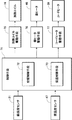
本調理器の制御系統について、図2を参照しながら説明する。同図において、71はマイクロコンピュータなどからなる制御手段で、これは前記鍋温度センサ21および蓋温度センサ47からの各温度情報に基づいて、炊飯時および保温時に鍋11の底部を加熱する加熱コイル16と、鍋11の側部を加熱するコードヒータ26と、蓋体5を加熱する蓋ヒータ46とを各々制御するものである。特に本実施例の制御手段81は、鍋温度センサ21の検出温度に基づいて主に加熱コイル16が制御されて鍋11の底部を温度管理し、蓋温度センサ47の検出温度に基づいて主に蓋ヒータ46を制御して放熱板37ひいては内蓋41を温度管理するようになっている。制御手段71は、自身の記憶手段(図示せず)に記憶されたプログラムの制御シーケンス上の機能として、被調理物の調理加熱を制御する調理制御手段を備えており、ここでは炊飯時に前記鍋11内の被調理物を炊飯加熱する炊飯制御手段72と、保温時に鍋11内のご飯を所定の保温温度に保温加熱する保温制御手段73とをそれぞれ備えている。
【0041】
75は、制御手段71からの制御信号を受けて、加熱コイル16に所定の高周波電流を供給する高周波インバータ回路などを内蔵した加熱コイル駆動手段である。またこれとは別に、制御手段71の出力側には、制御手段71からの制御信号を受けて、放熱板37や内蓋41を加熱するように蓋ヒータ46を駆動させる蓋ヒータ駆動手段76と、制御手段71からの制御信号を受けてコードヒータ26をオンにするコードヒータ駆動手段77が各々設けられる。前記炊飯制御手段72による炊飯時、および保温制御手段73による保温時には、鍋温度センサ21と、蓋温度センサ57からの各温度検出により、加熱コイル16による鍋11の底部への加熱と、コードヒータ26による鍋11の側面への加熱と、蓋ヒータ46による蓋体5への加熱が行なわれるように構成する。また、前記炊飯制御手段72による炊飯が終了し、鍋11内の被調理物がご飯として炊き上がった後は、保温制御手段73による保温に自動的に移行し、鍋温度センサ21の検知温度に基づき、加熱コイル16やコードヒータ26による鍋11への加熱を調節することで、ご飯を所定の保温温度(約70℃〜76℃)に保温するように構成している。
【0042】
特に前記コードヒータ26による加熱について補足説明すると、炊飯後にご飯の温度が約100℃から約73℃の保温温度に低下するまでと、約73℃の保温安定時に、コードヒータ26を発熱させて、蓋体5と保温釜本体1との隙間30の空間に金属板29から熱放射して、この隙間30からの外気の侵入による冷えを抑制すると共に、鍋11のフランジ部14を加熱する。また、保温時にご飯を再加熱する期間にもコードヒータ26により鍋11のフランジ部14を加熱し、ご飯の加熱により発生する水分が鍋11の内面上部に結露することを防止するように構成している。
【0043】
次に、上記構成についてその作用を説明する。鍋11内に被調理物である米および水を入れて、炊飯制御手段72による炊飯を開始すると、鍋温度センサ21による鍋11の底部の温度検知に基づいて、加熱コイル16とコードヒータ26で鍋11の底部と側面部をそれぞれ加熱し、鍋11内の水温を45〜60℃に15〜20分間保持するひたし炊きが行なわれる。その後、加熱コイル16により鍋11を強加熱し、被調理物への沸騰加熱を行なう。この沸騰加熱時に鍋11の底部の温度が90℃以上になり、蓋体5の温度が90℃以上で安定したら、鍋11内が沸騰状態になったものとして、それまでよりも加熱量を低減した沸騰継続加熱に移行する。なお、蓋体5の温度が90℃以上で安定したことは、蓋温度センサ47からの検出温度の温度上昇率により検知される。また、この沸騰検知において、鍋温度センサ21と蓋温度センサ47とにより、鍋11の底部および蓋体5がいずれも90℃以上になったことを確認でき、完全に鍋11内が沸騰したことを精度よく検知できる。
【0044】
また、前記鍋11の底部または蓋体5のいずれかが120℃以上の通常ではあり得ない検知温度になったら、制御手段71は何らかの異常があると判断して炊飯加熱における加熱量を低減して全ての動作を停止する切状態にするか、後述するむらしに移行するか、保温を行ない、異常加熱を防止する。逆に、前記鍋11の底部または蓋体5のいずれかが90℃以上になって所定時間(例えば5分)経過しているのに、それ以外の鍋11の底部または蓋体5のいずれかが90℃未満の低い状態の場合、この温度の低い状態の鍋温度センサ21または蓋温度センサ47が、何らかの理由(汚れや傾きや接触不良など)で温度検知精度が悪化していると判断し、同様に炊飯加熱における加熱量を低減して全ての動作を停止する切状態にするか、むらしに移行するか、保温を行ない、これに対処する。
【0045】
沸騰継続に移行すると、炊飯制御手段72は蓋ヒータ46による蓋加熱を開始させる。ここでの蓋加熱は、内蓋41の温度が100〜110℃になるように、蓋温度センサ47の検知温度により管理される。そして、鍋11の底部が所定の温度上昇を生じたら、炊き上げを検知して、むらしに移行する。むらし中は蓋温度センサ47の検出温度による温度管理によって蓋ヒータ46を通断電し、内蓋41への露付きを防止すると共に、ご飯が焦げない程度に高温(98〜100℃)が保持されるように、鍋11の底部または鍋11の側面部の温度を管理する。むらしは所定時間(15〜20分)続けられ、むらしが終了したら保温制御手段73による保温に移行する。
【0046】
保温になると、加熱コイル16にて鍋11の底部と側面下部を加熱すると共に、鍋11内に収容するご飯の温度よりも僅かに高く、蓋ヒータ46により蓋体5の下面を加熱し、さらに鍋11の側面をコードヒータ26でご飯が乾燥せず、かつ露が多量に付着しないように温度管理する。ご飯は70〜76℃に温度保持する。この保温時も、鍋温度センサ21または蓋温度センサ47が相互に異常に高かったり、逆に低かったりした場合は異常を検知して、この異常加熱を防止する。
【0047】
次に、鍋11の構成について、図3及び図4を参照して説明する。先ず、本実施例における調理用の鍋11を、特定の調理器用としてではなく、例えば誘導加熱コンロなどに載置して単体で使用することも考慮した構成を、図3から順に説明する。
【0048】
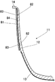
図3における調理用の鍋11は、鍋11の外面に、鍋11の主材料である鍋本体12よりも熱伝導性の悪い材料からなる断熱部材81を覆っている。ここでいう鍋11の外面とは、発熱体13を接合していない鍋11の外側部のみならず、発熱体13を接合した鍋11の外面の側面下部や底面部を含んでおり、そのいずれかの部位に断熱部材81が覆われていればよい。また断熱部材81は、耐熱性および耐食性に優れた材料であれば、どのような材料であっても構わない。
【0049】
こうして、鍋本体12よりも熱伝導性の悪い断熱部材81を鍋11の外面に覆うことで、調理時において鍋11からの放熱を抑えることができる。そのため、鍋11の温度を上昇させるための加熱を行なう必要がなく、調理性能および省エネルギー性能が向上すると共に、露付きなどの不具合も防止できる。また断熱部材81によって、鍋11の内部の被調理物に対する外気からの熱影響を抑制できる。しかも調理直後であっても、鍋11の外面が熱伝導性の悪い材料で覆われているため、素手で鍋11を取り扱うことができる。
【0050】
断熱部材81は凹凸嵌合により鍋11に設けれらる。鍋11の外面に凹部82を設ける場合では、その凹部82の製造方法は、切削でもよいし、絞り或いは曲げでもよい。また、凹部82は、鍋11の外面に環状に全周に設けても良いし、所々凹部82を設けなくてもよい。図3に示す構成では、フランジ部14側と高さ方向略中央側との上下2箇所に凹部82を設けている。このように2箇所に限らず、凹部82は何ヶ所設けてもよく、また、一定の高さに環状に設けても良いし、任意の高さでよい。
【0051】
一方、断熱部材81の内面には、前記凹部82に対応して凸部83を設ける。この凸部83も前記凹部82と同様に環状全周に連続して設けても良いし、所々凸部83を設けずに断続的に設けてもよい。
【0052】
また、鍋11の外面を断熱部材81覆う際に、鍋11の外面と断熱部材81の内面との間に隙間84を設けておく。この隙間84の大きさの設定は、鍋11と断熱部材82のそれぞれの材料固有の熱膨張率や収縮率から、使用する温度を考慮して決定することが望ましい。こうして、鍋11と断熱部材81との間に隙間84を形成することにより、鍋11の断熱効率が向上する。そのため、鍋11からの放熱と、外気からの熱影響をより抑制でき、調理性能および保温性能が一層向上すると共に、省エネルギー性能も一層向上する。また、調理直後の鍋11が熱い状態でも、隙間8により断熱部材81に熱が一層伝わりにくくなり、素手での鍋11の取扱いがさらに容易になる。また、断熱部材81は鍋11の外面との接触面積が減った分、調理加熱時における熱影響を受けにくくなり、故障時に異常加熱が行なわれた場合でも、断熱部材81が溶けたり変形することを、より確実に防止できる。
【0053】
特に、鍋11の外面底部は加熱コイル16と対向しているので、鍋11は比較的外気からの影響を受けにくい。それに対して、加熱コイル16に対向していない鍋11の側面中央からフランジ部14にかけては、鍋11は外気からの熱影響を受けやすい。そこで、特に外気からの影響を受けやすい箇所に配置した断熱部材81と鍋11との間に、上述した隙間84を設けて、静止空気層を構成する設計を行なうことで、さらにこの部分の断熱効率の向上を図ることが可能になる。
【0054】
鍋11の外面に設けた凹部82と、これに嵌合する断熱部材8の内面に設けた凸部83とを、任意の高さで複数個設ける際は、凸部83は全周に設けずに、所々凸部83をなくすように断続的に設けることが好ましい。こうすることで、鍋11の外面と断熱部材81の内面との間に入った水などを外に排出し易くなる。
【0055】
図3に示す構成では、フランジ部14を除いて、発熱体13を接合していない鍋11の外側部にかけて断熱部材81により連続して覆われている。発熱体13の部分を覆わないのは以下の理由である。鍋11の外面の側面下部から底面部にかけて接合してある発熱体13が、加熱コイル16から発する渦電流により発熱して鍋11を加熱する。すなわち、調理中に発熱体13は高温になることから、発熱体13からの熱影響を避けるために、鍋本体12よりも熱伝導性の悪い断熱部材81を発熱体13に配置しないことが好ましい。
【0056】
そして、鍋11の外面の側面下部から底面部にかけて接合した発熱体13は、調理中に発熱して高温になるが、断熱部材81はそれを避けた位置、すなわち鍋11の外側面を覆って設けられているため、発熱体13の直接的な熱影響を受けず、高温状態で使用されることを回避できる。したがって、鍋11としての製品寿命を延ばすことができる。
【0057】
なお、クラッド材のように、鍋11の全周に発熱体13が設けられた調理用の鍋11の場合、加熱コイル16から発する渦電流により発熱体13の温度が上昇した場合に、熱影響が少なく、かつ故障時なで加熱コイル16が通電し続ける異常加熱の場合においても、断熱部材81が溶けたり変形が生じない部分(鍋11の外側面)に、鍋主体12よりも熱伝導性の悪い材料で形成した断熱部材81を配置すればよい。
【0058】
このように本実施形態では、鍋11を備え、この鍋11の主材料たる鍋主体12より熱伝導性が悪い材料からなる部材である断熱部材81により鍋外面を覆い、この鍋11の外面に凹部82を設け、断熱部材81に凸部83を設け、鍋外面の凹部82と凸部83嵌合して断熱材料81で鍋外面を覆うから、凹部82に凸部83を嵌合させることで、製造性のばらつきにより変形した鍋にも、鍋11の主材料より熱伝導性が悪い材料で構成した部材である断熱部材81を容易に組み付けて覆うことができる。よって、鍋11からの放熱と、外気からの熱影響を抑制し、製造性を向上することができる。
【0059】
また、このように本実施形態では、鍋11の外面と鍋11の主材料である鍋本体12より熱伝導性が悪い材料である断熱部材81の内面との間に隙間84を設けたから、両者の間に静止空気層を作成し、断熱効果を得ることができると同時に、断熱部材81の膨張、収縮による影響を抑制することができる。
【0060】
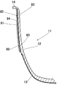
図5は本発明の第2実施形態を示し、上記第1実施形態と同一部分に同一符号を付し、その詳細な説明を省略して詳述すると、同図は鍋11の外面に凸部83、断熱部材81の内面に凹部82を設けた例を示す。このように鍋11の外面に凸部83を設ける場合も同様で、その凸部83の製造方法は、切削でもよいし、絞り或いは曲げでもよい。また、凸部83は、鍋11の外面に環状に全周に設けても良いし、所々凸部83を設けなくてもよい。図5に示す構成では、フランジ部14側と高さ方向略中央側との上下2箇所に凸部83を設けている。このように2箇所に限らず、凸部83は何ヶ所設けてもよく、また、一定の高さに環状に設けても良いし、任意の高さでよい。
【0061】
一方、断熱部材81の内面には、前記凸部83に対応して凹部82を設ける。この凹部82も前記凸部83と同様に環状全周に連続して設けても良いし、所々凹部82を設けずに断続的に設けてもよい。
【0062】
また、鍋11の外面を断熱部材81に覆う際に、鍋11の外面と断熱部材81の内面との間に隙間84を設けておく。この隙間84の大きさの設定は、鍋本体12と断熱部材8のそれぞれの材料固有の熱膨張率や収縮率から、使用する温度を考慮して決定することが望ましい。鍋11の外面に設けた凹部82と、これに嵌合する断熱部材83の内面に設けた凸部83とを、任意の高さで複数個設ける際は、凸部83は全周に設けずに、所々凸部83をなくすように断続的に設けることが好ましい。こうすることで、鍋11の外面と断熱部材81の内面との間に入った水などを外に排出し易くなる。
【0063】
そして、鍋11の外面に凸部83を設ける場合でも、断熱部材81の内面に凸部83を設ける場合でも、複数設ける際、任意の高さにある凸部83の上には凸部83を配置しないことや、鍋11の周囲の任意の位置では、上から下まで凸部83を部分的に設けないようにすることにより、水などを更に排出し易くなる。
【0064】
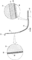
図6は本発明の第3実施形態を示し、上記各実施形態と同一部分に同一符号を付し、その詳細な説明を省略して詳述する。この例では、鍋11の外面にセラミック層91を設ける。このセラミック層91は、セラミック溶射を施して形成することができる。さらに、セラミック層91の上に塗装をコーティングして塗装層92を設ける。この塗装材料は、耐熱性や耐薬品性を備え、強度に優れたものが望ましく、溶射するセラミックは、酸化アルミナ(Al)と酸化チタン(TiO)の混合物のように熱伝導特性の悪いものが望ましく、鍋11の主材料である鍋本体12より熱伝導性が悪い材料を用いることにより、前記セラミック層91は断熱部材となる。尚、セラミック溶射以外にもセラミックのコーティングによりセラミック層91を形成してもよい。
【0065】
このようにセラミックに熱伝導特性が悪い材料を選定する理由は、断熱特性を高めるためである。よって、鍋外面に施すセラミック溶射やセラミックコーティングの厚さは、厚いほうが望ましい。あまり厚くすると鍋重量が重くなり、使い勝手が悪くなる。また、製造的な制約あるので、それら全般を考慮してセラミック層91の厚さを決定することが望ましい。
【0066】
このように本実施形態では、鍋11と、この鍋11を加熱する加熱手段たる加熱コイル16と、この鍋11と加熱コイル16とを備えた調理器において、鍋11の外面にセラミック溶射又はセラミックコーティングを施したから、鍋外面の断熱性を向上させることができ、鍋11からの放熱と、外気の熱影響を抑制できる。よって、炊飯性能・保温性能を向上させることと、省エネルギー性能を向上させることが可能となる。また、断熱性が向上するので、炊飯直後のような鍋11が熱い状態であっても、鍋11を持つ部分は素手で持てる低い温度になり、鍋11を素手で取り扱えるので使用性を向上させた炊飯器を提供することができる。
【0067】
図7は本発明の第4実施形態を示し、上記各実施形態と同一部分に同一符号を付し、その詳細な説明を省略して詳述する。この例では、鍋温度センサ21が当接する範囲は、鍋11の外面に前記セラミック層91を設けていない。そして、図1に示したように、鍋温度センサ21は、鍋11の底部外面に当接して設けられており、第3実施形態のように鍋11の外面にセラミック層91を設けると、前記鍋温度センサ21がセラミック層91に当接することになる。そのセラミック層91は断熱性が悪いため、鍋温度センサ21により鍋11の温度を正確に測定することができなくなるが、セラミック層91を鍋温度センサ21の当接部21Aに設けないから、鍋温度センサ21がセラミック層91の影響を受けないため、鍋11の温度を正確に測定できる。尚、当接部21Aとは、鍋11の鍋温度センサ21に当接する部分である。
【0068】
このように鍋11と、この鍋11を加熱する加熱手段たる加熱コイル16と、鍋11に当接し鍋11の温度を検出する鍋温度検出手段たる鍋温度センサ21と、この鍋温度センサ21の検出温度により加熱コイル16を制御する制御手段71と、これら鍋11と加熱コイル16と鍋温度センサ21とを収納する本体1とを備え、鍋温度センサ21が当接する範囲は、鍋11の外面にセラミック層91を設けないから、鍋11の温度を正確に測定でき、調理・保温性が低下することを防止できる。また、鍋温度センサ21の当接部21Aを避けるようにセラミック層91を設け、当接部21A以外はセラミック層で鍋11の外面を覆っているので、断熱性を向上させた炊飯器を提供することができる。
【0069】
図8〜図9は本発明の第5実施形態を示し、上記各実施形態と同一部分に同一符号を付し、その詳細な説明を省略して詳述する。この例では、鍋外面底部に設けた磁性金属部である発熱体13或いは鍋収納部下である内枠8の対向部に、前記セラミック層91を設けていない。また、鍋温度センサ21が当接する範囲である当接部21Aには、鍋11の外面に前記セラミック層91をけていない。図9は鍋11の部分正面図であり、点々の部分がセラミック層91を設けた部分である。このように鍋11の全周にセラミック層91を設けないのは以下の理由である。
【0070】
前記鍋11の内面に、フッ素樹脂など耐蝕性、耐久性などに優れたコーティングが施されている。これは、鍋11内で洗米を可能とするためである。また、鍋11の内面にはそれぞれ炊飯メニューに応じた水平線(図示せず)を設けておく。米と水をこの水平線に合わせてそれぞれ炊飯に適した米と水の合計量を提供できる。鍋11は、通常外部の台に置いたとき、鍋自身の重量を受け、姿勢を保つような形状になっている。これは前述の洗米や水位線合わせなどの作業を容易に行うためでもある。そのため、鍋外面の全面にセラミック溶射、或いはセラミックコーティングを施し、洗米或いは水位線合わせを行うと、必ず鍋外面に設けたセラミック層が外部の台と接触することになる。この場合、セラミック層91は固い特性を持つので、台を傷つけてしまう虞がある。一方、セラミック層91は脆い性質も有する。よって耐衝撃性に劣るので落下には弱い。鍋11を落としたとき、落とし方にもよるが大抵は鍋底から落ちる場合が多い。そして、洗米或いは水位線合わせを行っている際に、不用意に鍋を落としてしまうと、重たい鍋底が先に床面などにぶつかる。つまり、鍋底にセラミック層があると、セラミック層からぶつかことになる。セラミック層は脆いので床面などにぶつかったセラミック層部分は、割れが生じる虞がある。
【0071】
以上のことから、鍋底部にセラミック層91を設けないほうが使用性の高い商品となる。但し、セラミック層91は断熱性向上の目的があるので、セラミック層91を設けない範囲を最低限とすることが好ましい。鍋11を加熱する加熱コイル16は、通常鍋底部から鍋側底部にかけて設ける場合が多いので、その範囲のみセラミック層91を設けない設計が有効である。また、磁性金属である発熱体13と、熱伝導特性の良好な金属の異種金属による一体成形の鍋11の場合は、加熱コイル16より発熱を受ける発熱体13の部分のみセラミック層91を設けない設計も有効である。
【0072】
また、加熱コイル16の対向部に断熱部材81を設けない鍋11の場合、鍋11の外面底部は加熱コイル16と対向しているので、鍋11は比較的外気からの影響を受けにくいものの、逆に加熱コイル16からの熱影響は受けやすい。加熱コイル16の熱影響とは、加熱コイル16により発熱した発熱体13からの熱伝導や、加熱コイル16と鍋11との間にある空間が温められることによる熱輻射などの影響である。
【0073】
調理器の故障などの異常時には、加熱コイル16が連続動作するため、正常時と比べると、鍋11が受ける加熱量は数倍にも達し、加熱コイル16からの熱影響を最も受けやすい加熱コイル16の対向部に断熱部材81を配置すると、断熱部材81が溶けたり変形するなどの弊害を生じる可能性がある。そのため、加熱コイル16からの熱影響を最も受けやすい加熱コイル16の対向部には、断熱部材81の配置を避ける。これにより、断熱部材81の溶けや変形などの弊害を有効的に防止することができる。
【0074】
また、図1に示したように、鍋温度センサ21は、鍋11の底部外面に当接して設けられており、第3実施形態のように鍋11の外面にセラミック層91を設けると、前記鍋温度センサ21がセラミック層91に当接することになる。そのセラミック層91は断熱性が悪いため、鍋温度センサ21により鍋11の温度を正確に測定することができなくなるが、セラミック層91を鍋温度センサ21の当接部21Aに設けないから、鍋温度センサ21がセラミック層91の影響を受けないため、鍋11の温度を正確に測定できる。
【0075】
このように本実施形態では、外側底部に設けた熱伝導性が良好な磁性金属たる発熱体13と熱伝導性が良好な金属である鍋本体12とから一体成形により構成された鍋11を備え、この鍋11を収納自在にする鍋収納部9は、下方で発熱体13の近傍を覆うように設けた鍋収納部下たる内枠8と、上方の鍋収納上たる内枠カバー6及び内枠上部6とからなり、内枠カバー6の外側には鍋11に設けた発熱体13を発熱させる加熱コイル16を設け、鍋11と鍋収納部8と加熱コイル16を本体1に収納し、鍋11の外面にセラミック層91を設けた調理器において、発熱体13又は内枠8の対向部にはセラミック層91を設けないから、鍋11を外部台などに置いたときの傷つきや、落下時の割れ等を防止でき、使い勝手を向上させることができる。また、鍋11の外面の断熱性が向上するので、鍋11からの放熱と、外気からの熱影響を抑制することができる。
【0076】
また、このように本実施形態では、鍋11に当接し鍋11の温度を検出する鍋温度検出手段たる鍋温度センサ21を備え、この鍋温度センサ21が当接する範囲は、鍋11の外面にセラミック層91を設けないから、鍋11の外面に設けたセラミック層91を鍋温度センサ21の当接部21Aに配置しないことで、鍋11の温度を正確に測定でき、炊飯・保温性能を低下することを防止できる。
【0077】
図10は本発明の第6実施形態を示し、上記各実施形態と同一部分に同一符号を付し、その詳細な説明を省略して詳述する。この例では、鍋外面で磁性金属である発熱体13以外のアルミニウムにセラミック層91を設け、鍋11の内外面にコーティングを行い、高温の炉に入れて鍋を焼く。アルミニウムは加熱され膨張する。実使用上の温度は高くても100〜150℃であるので、アルミニウムの膨張量もかなり大きい物となる。(アルミニウムの熱膨張率:25×10−6(1/K))鍋11の外面に施したセラミック層91を全周環状に設けると、アルミニウムの熱膨張率はセラミック層91の膨張率(セラミック層91の熱膨張率:7.3×10−6(1/K))は小さいので、全周環状に設けたセラミック層91は、剥離や割れを生じる虞がある。このような熱膨張率の際による弊害を緩和するために、セラミック層91を全周環状に設けずに、セラミック層91を所々切り離して設けておく。図10は、セラミック層を設けない部分93を鍋11の外周に設けることにより、鍋11の外面に複数のセラミック層91,91を設けており、すなわち周方向に隣合うセラミック層91,91の間に、セラミック層を設けない部分93を設けた鍋11を図示している。こうすることで、鍋本体12のアルミニウムの膨張により、セラミック層91が外への力を受けても、全周環状に設けていないので、剥離や割れを生じることがない。
【0078】
このように本実施形態では、本体1と、鍋11と、この鍋11を加熱する加熱手段たる加熱コイル16とを備え、鍋11の外面にセラミック層91を設けた調理器において、セラミック層91を鍋11の外面の全周に連続して設けずに複数のセラミック層91,91で鍋11の外面を覆ったものであるから、鍋外面をその外面周方向に分割された複数個のセラミック層91,91…で覆うことで、鍋11の加熱・冷却による膨張・収縮の影響を緩和させることができる。よって、セラミック層91の鍋外面からの剥離やセラミック層91の割れを防止できる。また、鍋11の外面にセラミック層91を設けることで、鍋11の外面の断熱性を向上させる。よって、断熱性と省エネルギー性を向上することができる。
【0079】
なお、本発明は上記実施例に限定されるものではなく、種々の変形実施が可能である。例えば、クラッド材のように鍋の全周に発熱体を設けた構造のものでも、同様に対応すればよい。
【0080】
【発明の効果】
本発明の請求項1の調理容器によれば、容器からの放熱を抑えると共に、省エネルギー性に優れ、しかも調理直後であっても素手で取り扱うことができ、一層断熱性が向上する。
【0081】
本発明の請求項2の調理容器によれば、容器からの放熱を抑えると共に、省エネルギー性に優れ、しかも調理直後であっても素手で取り扱うことができ、一層断熱性が向上する。
【0082】
本発明の請求項の調理器によれば、容器からの放熱を抑えると共に、省エネルギー性に優れ、しかも調理直後であっても素手で取り扱うことができる。また、鍋外面の断熱性を向上することができる。セラミック層の鍋外面からの剥離やセラミック層の割れを防止できる。
【0083】
本発明の請求項の調理器によれば、容器からの放熱を抑えると共に、省エネルギー性に優れ、しかも調理直後であっても素手で取り扱うことができる。また、容器の状態を正確に測定でき、検出精度の悪化に起因する調理性能や保温性能の低下を防止できる。セラミック層の鍋外面からの剥離やセラミック層の割れを防止できる。
【0084】
本発明の請求項の調理器によれば、容器からの放熱を抑えると共に、省エネルギー性に優れ、しかも調理直後であっても素手で取り扱うことができる。また、鍋外面の断熱性を向上することができる。容器の状態を正確に測定でき、検出精度の悪化に起因する調理性能や保温性能の低下を防止できる。セラミック層の鍋外面からの剥離やセラミック層の割れを防止できる。
【図面の簡単な説明】
【図1】 本発明の第1実施形態を示す調理器の断面図である。
【図2】 同上制御系統の機能構成をあらわしたブロック図である。
【図3】 同上外面を断熱部材で覆った容器の部分断面図である。
【図4】 同上凹部と凸部の拡大断面図である。
【図5】 本発明の第2実施形態を示す外面を断熱部材で覆った容器の部分断面図である。
【図6】 本発明の第3実施形態を示す外側面をセラミック層で覆った容器の部分断面図であり、一部を拡大断面図にしている。
【図7】 本発明の第4実施形態を示す検出手段と鍋と当接部周りの断面図である。
【図8】 本発明の第5実施形態を示す調理器の断面図である。
【図9】 同上容器の部分正面図である。
【図10】 本発明の第6実施形態を示す容器の部分正面図である。
【符号の説明】
6 内枠上部(収納部上)
7 内枠カバー(収納部上)
8 内枠(収納部下)
9 鍋収納部(収納部)
11 鍋(容器)
12 鍋本体(容器本体)
13 発熱体(磁性金属)
16 加熱コイル(加熱手段)
21 鍋温度センサ(鍋温度検出手段・検出手段)
81 断熱部材(熱伝導性の悪い材料)
82 凹部
83 凸部
隙間
91 セラミック層(セラミック)
[0001]
BACKGROUND OF THE INVENTION
  The present invention relates to a cooking container and a cooking device in consideration of cooking performance, heat retention performance, energy saving performance and usability.
[0002]
[Problems to be solved by the invention]
  Conventionally, a pan intended for cooking of this type uses a material having excellent thermal conductivity (for example, aluminum) or a material having poor thermal conductivity (for example, stainless steel) as a main material. The main purpose of using materials with excellent thermal conductivity is to transmit heating energy quickly into the pan, and the main purpose of using materials with poor thermal conductivity is to suppress heat dissipation from the pan. is there.
[0003]
  Pans made mainly of materials with excellent thermal conductivity (for example, aluminum) cause the temperature of the pan to drop due to heat dissipation from the pan during cooking, and the cooking performance deteriorates. It is necessary to heat. In addition, there are problems such as dew condensation due to temperature decrease during heating, heating for increasing the temperature of the pan, and problems such as deterioration in cooking performance and heat retention, and energy saving performance.
[0004]
  On the other hand, pots made of materials with poor thermal conductivity (for example, stainless steel) require more heating than pots with materials with excellent thermal conductivity in order to raise the temperature in the pot during cooking and heat insulation. Therefore, the heating must be performed more than necessary, and the energy saving performance is lowered. Furthermore, regardless of whether the thermal conductivity was good or bad, when the pan immediately after cooking was hot, it could not be handled with bare hands, reducing usability.
[0005]
  Moreover, when the member which comprises the member comprised with the material whose heat conductivity is worse than the main material of a pan and a pan is comprised by integral molding, there existed the following problem.
[0006]
  The pan is coated and printed to improve its corrosion resistance and ease of use. At that time, it is necessary to bake the pot in a furnace in order to bake the coating or printing. As a result, the shape of the pan is deformed by heat. The deformation reduces the workability of the integral molding and the appearance quality of the finished parts. A pan formed by repeating drawing and bending operations with a press machine or the like has a similar problem that it is difficult to have a uniform shape. As a result, a pan having no shape change is required, and the productivity of the pan is reduced.
[0007]
  There is almost no gap between the pan immediately after being formed by integral molding and a component composed of a material having lower thermal conductivity than the main material of the pan. However, when heating is repeated during cooking, the gap between parts made of materials that have lower thermal conductivity than the main material of the pan and pan repeats thermal expansion, gradually conducting heat from the outer surface of the pan and the main material of the pan. A change occurs in the inner surface dimension of a member made of a material having poor properties. As a result, a gap is generated. In addition, when the pan heated by heat is cooled, contraction opposite to the thermal expansion is generated. The pan is made of metal, and when the member made of a material with lower thermal conductivity than the main material of the pan is made of synthetic resin, the amount of shrinkage of the synthetic resin relative to the metal is extremely large. A member made of a material with lower thermal conductivity than the main material of the material repeatedly expands and contracts, and the outer surface of the pan presses the inner surface of the component made of a material with lower thermal conductivity than the main material of the pan, causing discoloration and deformation And the appearance quality is lowered, and in the worst case, cracks are generated from the portion, and the commercial value may be lowered.
[0008]
  By the way, the pot which cooks rice with water and rice is heated by a heating means and cooks rice. In that case, it was easy to receive the heat influence from the outside air from the upper part to the side part of the rice cooker, and especially when the outside air temperature was low, both the rice cooking and heat retaining performance were lowered. In order to prevent such performance degradation, the side part is heated from the upper part of the pan. Examples are a side heater for heating the side of the pan and a flange heater for heating the flange of the pan.
[0009]
  However, even if a heating means for heating the side portion from the upper part of the pan is provided, it is difficult to completely suppress the heat effect from the outside air. A gap is provided between the pot and the side from the top of the pot between the heating means, and the gap is affected by heat from the outside air. This is because the means for heating the side from the top of the pan warms the air in the gap so that the pan is not affected by the heat from the outside air.
[0010]
  In addition, in order to drive the heating means that heats the side from the upper part of the pan, electric power is required, and energization is frequently performed especially when the outside air temperature is low. It is a hindrance.
[0011]
  Also, when you finish eating rice immediately after cooking or while keeping warm, remove the pan from the main body and wash it. At that time, since the pan is in a hot state, handling with bare hands is not preferable because there is a risk of burns. For this reason, it is common to hold the flange provided at the top of the pan with a towel or the like and take it out of the main body. Even in that case, if the pan taken out with a towel is transported to a sink or the like, the towel touches the water remaining in the sink and cannot be used as a dry towel.
[0012]
  The present invention is intended to solve the above-mentioned problems, is excellent in energy saving, and can be handled with bare hands even immediately after cooking, enhances the appearance quality and merchantability, and improves the manufacturability and The purpose is to provide a cooker.
[0013]
[Means for Solving the Problems]
  According to the cooking container of claim 1 of the present invention, the container is deformed due to variations in manufacturability by providing the container with a recess and fitting it into a protrusion formed on a member made of a material having poor thermal conductivity. Can be covered with a member made of a material having poor thermal conductivity. Therefore, the heat radiation from the container and the heat effect from the outside air can be suppressed, and the productivity can be improved.
[0014]
  In addition, by providing a gap between the outside of the container and the inner surface of a member made of a material with poor thermal conductivity, a static air layer can be created to obtain a heat insulation effect, and at the same time, it is made of a material with poor thermal conductivity. The cooker which suppressed the influence by expansion and contraction of a member can be provided.
[0015]
  According to the cooking container of claim 2 of the present invention, by providing a convex portion on the container and fitting it into a concave portion provided on a member made of a material having poor thermal conductivity, the container deformed due to variations in manufacturability. Can be covered with a member made of a material having poor thermal conductivity. Therefore, the heat radiation from the container and the heat effect from the outside air can be suppressed, and the productivity can be improved.
[0016]
  AlsoYongBy providing a gap between the outside of the chamber and the inner surface of the member made of a material with poor thermal conductivity, a static air layer can be created to obtain a heat insulation effect, and at the same time, the member made of a material with poor thermal conductivity A cooker that suppresses the effects of expansion and contraction can be provided.
[0017]
  Claim3According to this cooker, ceramic spraying or ceramic coating can be applied to the container to improve the heat insulation of the container. Therefore, the heat radiation from the container and the heat influence from the outside air can be suppressed.
[0018]
  Moreover, since heat insulation improves, even if a container immediately after rice cooking is a hot state, the part with a container becomes low temperature which can be held with bare hands.
[0019]
Also, by applying ceramic to the container, creating a range without ceramic without providing it on the entire circumference of the ring, and covering the container with multiple ceramic layers, alleviating the effects of expansion and contraction due to heating and cooling of the container Can do. Therefore, peeling of the ceramic layer from the container and cracking of the ceramic layer can be prevented. Moreover, the heat insulation of a container is improved by providing a ceramic layer in a container. Therefore, heat insulation and energy saving can be improved.
[0020]
  Claim4According to this cooker, the ceramic layer provided in the container is not disposed at the contact portion of the detecting means, so that the temperature of the container can be accurately measured, and cooking and heat retention can be prevented from being lowered. Moreover, since the container is covered with the ceramic layer except for the contact part of the detection means, a rice cooker with improved heat insulation can be provided.
[0021]
Also, by applying ceramic to the container, creating a range without ceramic without providing it on the entire circumference of the ring, and covering the container with multiple ceramic layers, alleviating the effects of expansion and contraction due to heating and cooling of the container Can do. Therefore, peeling of the ceramic layer from the container and cracking of the ceramic layer can be prevented. Moreover, the heat insulation of a container is improved by providing a ceramic layer in a container. Therefore, heat insulation and energy saving can be improved.
[0022]
  Claim5According to this cooker, ceramic spraying is applied to the container, or ceramic coating is applied to the container, and the ceramic prepared in the container is not applied to the magnetic metal part provided on the container outer bottom or the opposing part below the storage part. By doing so, it is possible to prevent scratches when placed on a table or the like, cracks when falling, etc., and improve usability. Moreover, since the heat insulation of a container improves, the thermal radiation from a container and the thermal influence from external air can be suppressed.
[0023]
  AlsoYongBy not placing the ceramic provided in the cooker in the contact part of the detection means, the temperature of the container can be measured accurately, and rice cooking and heat retention performanceButIt can be prevented from decreasing.
[0024]
  AlsoYongBy applying ceramic to the container, creating a range without ceramic without providing it all around the ring, and covering the container with multiple ceramic layers, the influence of expansion and contraction due to heating and cooling of the container can be mitigated . Therefore, peeling of the ceramic layer from the container and cracking of the ceramic layer can be prevented. Moreover, the heat insulation of a container is improved by providing a ceramic layer in a container. Therefore, heat insulation and energy saving can be improved.
[0025]
DETAILED DESCRIPTION OF THE INVENTION
  Hereinafter, an embodiment of a cooking device according to the present invention will be described with reference to FIGS. In addition, the cooking device in a present Example is a heat retention pot.
[0026]
  In FIG. 1, reference numeral 1 denotes a warming pot main body that is an outer shell of the warming pot, and the warming pot main body 1 is provided so as to cover a substantially cylindrical outer frame 2 that forms a body portion and a lower surface opening of the outer frame 2. The bottom plate 3 is formed. A lid that can be opened and closed by a hinge spring 4 as an elastic member located at the rear portion, that is, a lid body 5 is disposed at the upper portion of the heat retaining pot main body 1. Also, a substantially cylindrical inner frame upper part 6 formed by being integrally suspended from the upper inner peripheral part of the outer frame 2, a substantially cylindrical inner frame cover 7 connected to the lower surface opening of the inner frame upper part 6, and an inner frame The inner frame 8 provided so as to cover the lower surface opening of the cover 7 forms a pot storage portion 9 which is a bottomed cylindrical storage portion in the heat insulating main body 1. In addition, the inner frame upper part 6 which makes the side part of the pan accommodating part 9 consists of synthetic resins, such as PP (polypropylene) integrated with the outer frame 2. As shown in FIG. Moreover, the inner frame 8 which makes the bottom part of the pot accommodating part 9 is formed with synthetic resins, such as PET (polyethylene terephthalate). And the inner frame upper part 6 and the inner frame cover 7 are on the pan storage part which is a storage part, and the inner frame 8 is under the pan storage part which is a storage part.
[0027]
  In addition, although the external appearance of the heat insulation main body 1 is comprised by the outer frame which integrated the upper part and the side part, ie, the outer frame 2, and the baseplate 3 which covers a bottom part, the top frame which covers an upper part, a side part, and a bottom part You may comprise the external appearance of the heat retention pot main body 1 with the bottom side frame which integrated. Moreover, you may comprise by the upper frame which covers an upper part, the side frame which covers a side part, and the baseplate which covers a bottom part. At that time, the outer frame, the bottom plate, the upper frame, and the bottom frame are all formed of a synthetic resin such as PP. The side frame may be formed of the same synthetic resin such as PP, or a metal plate such as stainless steel.
[0028]
  In the pot storage part 9, a bottomed cylindrical container for storing an object to be cooked such as rice or water, that is, a pot 11 is detachably accommodated. This pan 11 includes a pan body 12 mainly made of aluminum having good thermal conductivity, and a heating element 13 made of a magnetic metal plate such as ferritic stainless steel joined from the lower side to the bottom of the outer surface of the pan body 12. It consists of. The reason why the heating element 13 is not provided on the upper side from the center of the side surface of the pan 11 is to reduce the weight of the pan 11. Further, an annular flange portion 14 extending to the outer peripheral side is formed on the upper portion of the pan 11, that is, around the upper end.
[0029]
  The inner frame 7 is positioned to face the heating element 13 of the pan 11, but the bottom of the pot 11, particularly the bottom part, is electromagnetically placed on the lower side and the bottom of the inner frame 7 facing the heating element 13. A heating coil 16 is provided as a heating means for the pot for induction heating. When a high frequency current is supplied to the heating coil 16, the heating element 13 of the pan 11 is heated by the alternating magnetic field generated from the heating coil 16, and the cooking object such as water and rice in the pan 11 is heated. It has become so. Further, a ferrite core 17 is provided so as to cover the heating coil 16 from below.
[0030]
  A thermistor-type pan temperature sensor 21 serving as a detecting means that elastically contacts the bottom outer surface of the pan 11 and detects the temperature of the bottom of the pan 11 is provided by a sensor holder 22 at the center of the bottom of the inner frame 7. It is supported and provided.
[0031]
  A cord heater 26 serving as a pan side heating means for heating the upper side of the pan 11, in particular, the flange portion 14, is provided at the upper end of the pan storage portion 9 of the warming pot main body 1. It is located in an annular shape. The cord heater 26 is an electrothermal heater, and is held on a spacer 27 as a heat dissipation suppressing member attached so as to be placed on the upper end of the pot storage portion 9. The cord heater 26 is attached to the spacer 27 so as to cover the cord heater 26 from above, and a metal plate 29 serving both as a metal fitting made of, for example, an aluminum plate having excellent thermal conductivity and a heat radiating portion is further provided. The metal plate 29 is positioned so as to face the gap 30 between the warming pot main body 1 and the lid 5. And the lower surface of the flange part 14 of the pan 11 is mounted on the upper surface of the said metal plate 29, and by this, the pan 11 is accommodated in the pan accommodating part 9 in the suspended state. Therefore, there is almost no gap between the pot 11 and the upper end of the pot storage portion 9 in which the pot 11 is stored. Moreover, the flange portion 14 of the pan 11 has an outer shape that is equal to or greater than the size of the cord heater 26, so that the cord heater 26 is covered with the flange portion 14 of the pan 11 from above. . However, although not shown, for example, by bending the cord heater 26 downward at the left and right side portions of the pan storage portion 9, the flange portion 14 and the cord heater 26 are brought into non-contact with each other. A gap is partially formed between the flange portions 14 and the flange portion 14 can be used as a handle portion when the pan 11 is attached and detached. Further, the gap also has an action of discharging steam when cooking rice with water attached to the outer surface of the pan 11.
[0032]
  The lid body 5 is urged in the opening direction by the force of the hinge spring 4 wound around the hinge shaft 31 that is a rotating shaft thereof. Further, the hook 5 as an opening / closing button provided on the upper front portion of the outer frame 2 is detachably engaged with the clamp 32 provided on the front portion of the lid body 5, so that the lid body 5 is closed. It is designed to be held in a state. The lid 5 includes an outer lid 36 that forms an upper shell of the upper surface, a heat radiating plate 37 as a lid lower surface material that forms a lower surface that is the inner surface of the lid 5, and the outer lid 36 and the heat radiating plate 37. The main component is an outer lid cover 38 as a lid base material that is joined to form the skeleton of the lid body 5. An inner lid 41 that directly covers the upper opening of the pan 11 is detachably mounted on the lower surface, which is the inner surface of the lid 5, with a predetermined gap formed between the lower surface and the lower surface. The heat radiating plate 37 and the inner lid 41 are both made of metal, and are made of, for example, a material obtained by anodizing stainless steel or aluminum. A packing base 42 is fixed to the outer peripheral portion of the inner lid 41, and a lid packing 43 is fixed by being sandwiched between the packing base 42 and the inner lid 41. The lid packing 43 is formed in an annular shape by an elastic member such as silicone rubber or fluororubber, abuts against the upper surface of the flange portion 14 of the pan 11 and closes the gap between the pan 11 and the inner lid 41. The steam generated from 11 is sealed. And the contact part to the pan 11 in the lid packing 43 is opposed to the cord heater 26 with the flange part 14 in between.
[0033]
  A lid heater 46 as a lid heating means is provided on the upper surface of the heat radiating plate 37 inside the lid body 5. The lid heater 46 may be an electric heating heater such as a cord heater or a heating coil by electromagnetic induction heating. Further, the heat radiating plate 37 is provided with a thermistor type lid temperature sensor 47 as lid temperature detecting means for detecting the temperature of the lid 5, particularly the inner lid 41. Further, a steam port 48 for releasing steam generated in the pan 11 to the outside is detachably attached to the rear upper surface of the lid 5.
[0034]
  The steam port 48 is provided detachably with respect to the outer lid 36, but may be integrated with the outer lid 36. Further, the steam port 48 is supported by a steam port packing 49 made of silicone rubber or the like attached to the outer lid 36, and this steam port packing 49 has a seal portion 49A having a substantially "<"-shaped cross section below. The hole 37 </ b> A provided in the heat radiating plate 37 passes through and is sealed by the inner lid 41. The inner lid 41 has a steam passage hole 41A for discharging steam in the pan, and the steam port 48 is connected to the steam passage hole 41A. Therefore, the steam generated from the inside of the pan is discharged out of the rice cooker,beneathIs sealed by the steam port packing 49 and the inner lid 41, so that the steam generated from the pan does not flow out into the lid 5.
[0035]
  On the other hand, the pan 11 is composed of a pan body 12 made of a member having good thermal conductivity and a heating element 13 joined to the outer surface of the pan body 12. From the inner bottom surface to the inner side surface, a process of providing an inner surface convex portion (not shown) protruding from the inner surface of the pan body 12 is performed. The range where the inner surface convex portion is provided is preferably at least the range where the heating coil 16 is opposed. This is because the heating element 13 of the pan 11 is disposed in a range opposite to the heating coil 16 and the pan 11 generates heat there.
[0036]
  The inner surface convex portion provided on the inner surface of the pan 11 has a larger boiling energy and a larger number of bubbles generated at the time of boiling than a portion (inner surface concave portion) where the inner surface convex portion is not provided. That is, when rice is cooked, the blow-up from the inner surface convex portion range is stronger than the other inner surface concave portion, and as a result, there are many sticks and the steam is also blown stronger. For this reason, if the connecting portion between the steam passage hole 41A of the inner lid 41 and the steam port 48 is on the inner surface convex portion, the steam port 48 will affect the influence of rice balls and steam immediately before boiling during rice cooking. It will be received greatly.
[0037]
  A heating control board 51 is provided inside the warmer main body 1 so as to be located at the rear part of the pot housing part 9. The heating control board 51 receives signals from the pan temperature sensor 21 and the lid temperature sensor 47, and controls the heating coil 16, which is a heating means, and the cord heater 26 and the lid heater 46. An element (not shown) to be driven is mounted. The element that drives the heating coil 16 is heated together with the oscillation of the heating coil 16, but since this element has a use temperature condition, it is necessary to drive the element at a certain temperature or lower in order to operate the element normally. For this reason, the element that drives the heating coil 16 is provided with a fin-like radiator 52 formed of a material having good thermal conductivity such as aluminum, for example, and heat from the radiator 52 by the wind emitted from the cooling fan 53. The element is cooled to below the operating temperature condition.
[0038]
  The cooling fan 53 that is a cooling means is disposed below or on the side of the radiator 52 attached to the heating control means 51. In addition, at the bottom or side of the heat insulating pot main body 1, a wind discharge for discharging to the outside the wind that is emitted from the cooling fan 53 and takes heat from the radiator 52 attached to the heating control means 51. A service hole 54 is provided. The heating control means 51 may be arranged at any position around the pan 11 in the heat insulating pot main body 1, and the wind discharge hole 54 may be arranged at any position accordingly. However, in recent years, the product has become smallerConversionIn view of the demand for design, it is preferable that the heating control means 51, the cooling fan 53, and the wind discharge hole 54 are arranged at substantially opposite positions across the pan 11.
[0039]
  An operation panel 61 as an operation unit is provided at the front portion of the outer lid 36. The operation panel 61 is made of a highly transparent material such as AS resin, and a printed sheet 61A is integrally formed on the surface by insert molding. In addition, a control substrate 63 is disposed in the substrate storage chamber 62 formed in the lid 5 and located below the operation panel 61. On the control board 63, an LCD 64 for displaying time and a selected menu, an LED 65 for displaying the current process, a switch 66 for starting rice cooking and selecting a menu, and the like are arranged on the upper surface. . An operation panel 61 above the control board 63 is provided for displaying button names, and by holding the board storage chamber 62 hermetically, various electronic components on the control board 63 are covered with dust and water. Is prevented from adhering. When the button on the operation panel 61 is pressed, the sheet 61A is bent, and the button of the operation button presses the switch 66 on the control board 63 so that the operation starts or stops.
[0040]
  A control system of the cooker will be described with reference to FIG. In the figure, reference numeral 71 is a control means comprising a microcomputer, etc., which is a heating coil for heating the bottom of the pan 11 during cooking and keeping warm based on the temperature information from the pan temperature sensor 21 and the lid temperature sensor 47. 16, a cord heater 26 that heats the side of the pan 11, and a lid heater 46 that heats the lid 5. In particular, the control means 81 of this embodiment mainly controls the temperature of the bottom of the pan 11 by controlling the heating coil 16 based on the temperature detected by the pan temperature sensor 21, and mainly based on the temperature detected by the lid temperature sensor 47. The lid heater 46 is controlled to control the temperature of the heat radiating plate 37 and the inner lid 41. The control means 71 includes cooking control means for controlling cooking heating of the cooking object as a function on the control sequence of the program stored in its own storage means (not shown). The rice cooking control means 72 which cooks and heats the to-be-cooked thing in 11 and the heat retention control means 73 which heat-retains the rice in the pan 11 to predetermined | prescribed heat retention temperature at the time of heat retention are each provided.
[0041]
  Reference numeral 75 denotes a heating coil driving means that incorporates a high-frequency inverter circuit that receives a control signal from the control means 71 and supplies a predetermined high-frequency current to the heating coil 16. Separately from this, the output side of the control means 71 receives a control signal from the control means 71 and a lid heater driving means 76 for driving the lid heater 46 so as to heat the heat radiating plate 37 and the inner lid 41. A code heater driving means 77 for turning on the code heater 26 in response to a control signal from the control means 71 is provided. At the time of cooking by the rice cooking control means 72 and at the time of heat insulation by the heat insulation control means 73, the heating coil 16 heats the bottom of the pot 11 by the temperature detection from the pan temperature sensor 21 and the lid temperature sensor 57, and the code heater. It heats to the side of the pan 11 by 26, and the cover 5 is heated by the lid heater 46. Moreover, after the rice cooking by the rice cooking control means 72 is finished and the cooked food in the pan 11 is cooked as rice, it automatically shifts to the heat retention by the heat insulation control means 73 and the temperature detected by the pan temperature sensor 21 is reached. Based on this, by adjusting the heating to the pan 11 by the heating coil 16 and the cord heater 26, the rice is kept at a predetermined temperature (about 70 ° C. to 76 ° C.).
[0042]
  In particular, the heating by the cord heater 26 will be explained supplementarily. Until the temperature of the rice drops from about 100 ° C. to about 73 ° C. after the rice cooking, the cord heater 26 is caused to generate heat when the temperature is kept stable at about 73 ° C. Heat is radiated from the metal plate 29 to the space 30 between the lid 5 and the warming pot main body 1 to suppress cooling due to intrusion of outside air from the gap 30 and the flange portion 14 of the pan 11 is heated. Further, the flange portion 14 of the pan 11 is heated by the cord heater 26 during the period of reheating the rice during the heat insulation, and the moisture generated by the heating of the rice is prevented from condensing on the inner upper surface of the pan 11. ing.
[0043]
  Next, the effect | action is demonstrated about the said structure. When rice and water which are to-be-cooked objects are put into the pan 11 and rice cooking by the rice control means 72 is started, the heating coil 16 and the code heater 26 are used based on the temperature detection of the bottom of the pan 11 by the pan temperature sensor 21. The bottom part and side part of the pan 11 are each heated, and the water temperature in the pan 11 is maintained at 45 to 60 ° C. for 15 to 20 minutes. Thereafter, the pot 11 is heated strongly by the heating coil 16 to boil and heat the food. When the temperature of the bottom of the pan 11 becomes 90 ° C. or higher during the boiling heating and the temperature of the lid 5 is stabilized at 90 ° C. or higher, it is assumed that the pan 11 is in a boiling state, and the heating amount is reduced more than before. Shift to continuous boiling heating. Note that the fact that the temperature of the lid 5 is stable at 90 ° C. or higher is detected by the temperature increase rate of the detected temperature from the lid temperature sensor 47. Moreover, in this boiling detection, it can be confirmed by the pan temperature sensor 21 and the lid temperature sensor 47 that both the bottom of the pan 11 and the lid 5 have reached 90 ° C. or more, and the inside of the pan 11 has completely boiled. Can be detected accurately.
[0044]
  When either the bottom of the pan 11 or the lid 5 reaches a detection temperature that is not normally 120 ° C. or higher, the control means 71 determines that there is some abnormality and reduces the heating amount in the rice cooking heating. In order to prevent abnormal heating, the operation is turned off to stop all operations, or shifts to unevenness, which will be described later, or heat is kept. Conversely, either the bottom of the pan 11 or the lid 5 has reached 90 ° C. or more and a predetermined time (for example, 5 minutes) has passed, but any of the bottom of the pan 11 or the lid 5 other than that. When the temperature is lower than 90 ° C., the pan temperature sensor 21 or the lid temperature sensor 47 in the low temperature state determines that the temperature detection accuracy has deteriorated for some reason (dirt, inclination, poor contact, etc.). Similarly, the amount of heating in rice cooking heating is reduced so that all operations are stopped, or the operation is shifted to unevenness, or the heat is kept, and this is dealt with.
[0045]
  When shifting to continuation of boiling, the rice cooking control means 72 starts lid heating by the lid heater 46. The lid heating here is managed by the temperature detected by the lid temperature sensor 47 so that the temperature of the inner lid 41 becomes 100 to 110 ° C. And if the bottom part of the pan 11 raises predetermined temperature, cooking will be detected and it will transfer to unevenness. During unevenness, the lid heater 46 is cut off by temperature control based on the temperature detected by the lid temperature sensor 47 to prevent dew condensation on the inner lid 41 and at a high temperature (98-100 ° C.) so that the rice does not burn. The temperature of the bottom part of the pan 11 or the side part of the pan 11 is managed so that it may be hold | maintained. The unevenness is continued for a predetermined time (15 to 20 minutes), and when the unevenness is completed, the operation shifts to heat retention by the heat retention control means 73.
[0046]
  When the temperature is kept warm, the heating coil 16 heats the bottom and the lower side of the pan 11 and is slightly higher than the temperature of the rice accommodated in the pan 11, and the lower surface of the lid 5 is heated by the lid heater 46. The temperature of the side surface of the pan 11 is controlled by the cord heater 26 so that the rice does not dry and a large amount of dew does not adhere. The temperature of the rice is maintained at 70 to 76 ° C. Even during this heat retention, if the pan temperature sensor 21 or the lid temperature sensor 47 is abnormally high or low, the abnormality is detected and this abnormal heating is prevented.
[0047]
  Next, the structure of the pan 11 is demonstrated with reference to FIG.3 and FIG.4. First, a configuration in which the cooking pan 11 in the present embodiment is not used for a specific cooker but is placed on an induction heating stove or the like and used alone will be described in order from FIG.
[0048]
  A cooking pan 11 in FIG. 3 covers the outer surface of the pan 11 with a heat insulating member 81 made of a material having lower thermal conductivity than the pan body 12 which is the main material of the pan 11. Here, the outer surface of the pan 11 includes not only the outer portion of the pan 11 to which the heating element 13 is not joined, but also the lower side portion and the bottom portion of the outer surface of the pan 11 to which the heating element 13 is joined. It suffices if the heat insulating member 81 is covered in such a part. The heat insulating member 81 may be any material as long as it is a material excellent in heat resistance and corrosion resistance.
[0049]
  Thus, by covering the outer surface of the pan 11 with the heat insulating member 81 having a thermal conductivity lower than that of the pan body 12, heat dissipation from the pan 11 can be suppressed during cooking. Therefore, it is not necessary to perform heating for raising the temperature of the pan 11, cooking performance and energy saving performance are improved, and problems such as dew can be prevented. Moreover, the heat influence from the external air with respect to the to-be-cooked thing inside the pot 11 can be suppressed by the heat insulation member 81. FIG. Moreover, even immediately after cooking, since the outer surface of the pan 11 is covered with a material having poor thermal conductivity, the pan 11 can be handled with bare hands.
[0050]
  The heat insulating member 81 is provided in the pan 11 by concave-convex fitting. In the case where the recess 82 is provided on the outer surface of the pan 11, the manufacturing method of the recess 82 may be cutting, drawing, or bending. Moreover, the recessed part 82 may be provided in the outer surface of the pan 11 cyclically | annularly, and the recessed part 82 does not need to be provided in some places. In the configuration shown in FIG. 3, the concave portions 82 are provided at two locations on the top and bottom of the flange portion 14 side and the height direction substantially center side. As described above, the number of the recesses 82 is not limited to two, and may be provided in any number, or may be provided in a ring shape at a certain height, or may be an arbitrary height.
[0051]
  On the other hand, a convex portion 83 is provided on the inner surface of the heat insulating member 81 so as to correspond to the concave portion 82. Similarly to the concave portion 82, the convex portion 83 may be provided continuously around the entire circumference of the ring, or may be provided intermittently without providing the convex portion 83.
[0052]
  Further, the outer surface of the pan 11 is insulated from the heat insulating member 81soWhen covering, a gap 84 is provided between the outer surface of the pan 11 and the inner surface of the heat insulating member 81. The setting of the size of the gap 84 is desirably determined in consideration of the temperature to be used, from the thermal expansion coefficient and contraction ratio specific to the material of the pan 11 and the heat insulating member 82. Thus, the heat insulation efficiency of the pan 11 is improved by forming the gap 84 between the pan 11 and the heat insulating member 81. Therefore, the heat radiation from the pan 11 and the heat influence from the outside air can be further suppressed, cooking performance and heat retention performance are further improved, and energy saving performance is further improved. Even when the pan 11 immediately after cooking is hot, the gap 84This makes it more difficult for heat to be transmitted to the heat insulating member 81, and the handling of the pan 11 with bare hands is further facilitated. In addition, the heat insulating member 81 is less affected by heat during cooking and heating because the contact area with the outer surface of the pan 11 is reduced, and the heat insulating member 81 melts or deforms even when abnormal heating is performed at the time of failure. Can be prevented more reliably.
[0053]
  In particular, since the bottom of the outer surface of the pan 11 faces the heating coil 16, the pan 11 is relatively less susceptible to the influence of the outside air. On the other hand, from the center of the side surface of the pan 11 not facing the heating coil 16 to the flange portion 14, the pan 11 is easily affected by heat from the outside air. Therefore, the gap 84 described above is provided between the heat insulating member 81 and the pan 11 that are particularly susceptible to the influence of outside air, and the design for forming a static air layer is further performed. Efficiency can be improved.
[0054]
  The recessed part 82 provided in the outer surface of the pan 11, and the heat insulation member 8 fitted to this1When a plurality of protrusions 83 provided on the inner surface are provided at an arbitrary height, it is preferable that the protrusions 83 be provided intermittently so as to eliminate the protrusions 83 without providing the protrusions 83 on the entire circumference. By doing so, it becomes easy to discharge water or the like that has entered between the outer surface of the pan 11 and the inner surface of the heat insulating member 81.
[0055]
  In the configuration shown in FIG. 3, except for the flange portion 14, it is continuously covered with a heat insulating member 81 over the outer portion of the pan 11 to which the heating element 13 is not joined. The reason why the portion of the heating element 13 is not covered is as follows. The heating element 13 joined from the lower side to the bottom of the outer surface of the pan 11 generates heat by the eddy current generated from the heating coil 16 and heats the pan 11. That is, since the heating element 13 becomes high temperature during cooking, it is preferable not to arrange the heat insulating member 81 having a lower thermal conductivity than the pan body 12 in the heating element 13 in order to avoid the heat effect from the heating element 13. .
[0056]
  And although the heat generating body 13 joined from the side surface lower part to the bottom face part of the outer surface of the pan 11 generates heat and becomes high temperature during cooking, the heat insulating member 81 covers the position avoiding it, that is, the outer surface of the pan 11. Since it is provided, it is not affected directly by the heat from the heating element 13 and can be avoided from being used in a high temperature state. Therefore, the product life as the pan 11 can be extended.
[0057]
  In addition, in the case of the cooking pan 11 in which the heating element 13 is provided on the entire circumference of the pan 11 like a clad material, when the temperature of the heating element 13 rises due to the eddy current generated from the heating coil 16, the heat influence is exerted. There are few and at the time of failureDoEven in the case of abnormal heating in which the heating coil 16 continues to be energized, heat insulation formed of a material having a lower thermal conductivity than the pan main body 12 in a portion (the outer surface of the pan 11) where the heat insulating member 81 does not melt or deform. The member 81 may be disposed.
[0058]
  As described above, in this embodiment, the pan 11 is provided, the outer surface of the pan is covered with the heat insulating member 81 that is a member made of a material having lower thermal conductivity than the main body 12 of the pan that is the main material of the pan 11, and the outer surface of the pan 11 is covered. The concave portion 82 is provided, the convex portion 83 is provided on the heat insulating member 81, and the concave portion 82 and the convex portion 83 on the outer surface of the pan are provided.TheSince the outer surface of the pan is covered with the heat insulating material 81, the heat conductivity is lower than the main material of the pan 11 even in the pan deformed due to the variation in manufacturability by fitting the convex portion 83 to the concave portion 82. It is possible to easily assemble and cover the heat insulating member 81 that is a member constituted by the above. Therefore, the heat radiation from the pan 11 and the heat influence from the outside air can be suppressed, and the productivity can be improved.
[0059]
  Further, in this embodiment, since the gap 84 is provided between the outer surface of the pan 11 and the inner surface of the heat insulating member 81 that is a material having lower thermal conductivity than the pan body 12 that is the main material of the pan 11, A still air layer can be created between them to obtain a heat insulating effect, and at the same time, the influence of expansion and contraction of the heat insulating member 81 can be suppressed.
[0060]
  FIG. 5 shows a second embodiment of the present invention, where the same reference numerals are given to the same parts as those in the first embodiment, and detailed description thereof is omitted. 83, the example which provided the recessed part 82 in the inner surface of the heat insulation member 81 is shown. Similarly, when the convex portion 83 is provided on the outer surface of the pan 11, the manufacturing method of the convex portion 83 may be cutting, drawing, or bending. Further, the convex portion 83 may be provided on the outer surface of the pan 11 in an annular shape on the entire circumference, or the convex portion 83 may not be provided in some places. In the configuration shown in FIG. 5, convex portions 83 are provided at two locations on the top and bottom of the flange portion 14 side and the substantially central side in the height direction. As described above, the number of the protrusions 83 is not limited to two, and may be provided in any number, may be provided in a ring shape at a constant height, or may have an arbitrary height.
[0061]
  On the other hand, the inner surface of the heat insulating member 81 is provided with a concave portion 82 corresponding to the convex portion 83. Similarly to the convex portion 83, the concave portion 82 may be provided continuously on the entire circumference of the ring, or may be provided intermittently without providing the concave portion 82 in some places.
[0062]
  Further, when the outer surface of the pan 11 is covered with the heat insulating member 81, a gap 84 is provided between the outer surface of the pan 11 and the inner surface of the heat insulating member 81. The size of the gap 84 is determined by the pan body 12 and the heat insulating member 8.1It is desirable to determine the temperature to be used from the thermal expansion coefficient and shrinkage ratio specific to each material. When providing a plurality of concave portions 82 provided on the outer surface of the pan 11 and convex portions 83 provided on the inner surface of the heat insulating member 83 fitted thereto, the convex portions 83 are not provided on the entire circumference. In addition, it is preferable to intermittently provide the convex portions 83 in some places. By doing so, it becomes easy to discharge water or the like that has entered between the outer surface of the pan 11 and the inner surface of the heat insulating member 81.
[0063]
  And even when providing the convex part 83 in the outer surface of the pan 11, even when providing the convex part 83 in the inner surface of the heat insulation member 81, when providing multiple, the convex part 83 is provided on the convex part 83 in arbitrary height. Water or the like can be more easily discharged by not providing the convex portion 83 partially from the top to the bottom at any position around the pan 11.
[0064]
  FIG. 6 shows a third embodiment of the present invention. The same reference numerals are given to the same parts as those of the above-mentioned embodiments, and detailed description thereof will be omitted. In this example, a ceramic layer 91 is provided on the outer surface of the pan 11. The ceramic layer 91 can be formed by ceramic spraying. Further, the paint layer 92 is provided by coating the ceramic layer 91 with paint. This coating material is heat and chemical resistantSexIt is desirable to have excellent strength, and the ceramic to be sprayed is alumina oxide (Al2O3) And titanium oxide (TiO2The ceramic layer 91 becomes a heat insulating member by using a material having a poor thermal conductivity, such as a mixture of), and using a material having a lower thermal conductivity than the pan body 12 which is the main material of the pan 11. In addition to ceramic spraying, the ceramic layer 91 may be formed by ceramic coating.
[0065]
  The reason for selecting a material having poor heat conduction characteristics for the ceramic is to improve the heat insulation characteristics. Therefore, it is desirable that the ceramic spraying or ceramic coating applied to the outer surface of the pan be thicker. If it is too thick, the pan weight will be heavy and the usability will be poor. Also, manufacturing constraintsButTherefore, it is desirable to determine the thickness of the ceramic layer 91 in consideration of all of them.
[0066]
  Thus, in this embodiment, in the cooking device provided with the pan 11, the heating coil 16 serving as a heating means for heating the pan 11, and the pan 11 and the heating coil 16, ceramic spraying or ceramic is applied to the outer surface of the pan 11. Since the coating is applied, the heat insulation of the outer surface of the pan can be improved, and the heat radiation from the pan 11 and the thermal effect of the outside air can be suppressed. Therefore, it becomes possible to improve rice cooking performance and heat retention performance and to improve energy saving performance. Moreover, since heat insulation improves, even if the pan 11 is in a hot state immediately after cooking, the portion with the pan 11 becomes a low temperature that can be held with bare hands, and the pan 11 can be handled with bare hands, improving usability. Rice cooker can be provided.
[0067]
  FIG. 7 shows a fourth embodiment of the present invention. The same reference numerals are given to the same parts as those of the above-described embodiments, and detailed description thereof will be omitted. In this example, the ceramic layer 91 is not provided on the outer surface of the pan 11 in the range where the pan temperature sensor 21 abuts. As shown in FIG. 1, the pan temperature sensor 21 is provided in contact with the bottom outer surface of the pan 11, and when the ceramic layer 91 is provided on the outer surface of the pan 11 as in the third embodiment, The pan temperature sensor 21 comes into contact with the ceramic layer 91. Since the ceramic layer 91 has poor heat insulation, the temperature of the pan 11 cannot be accurately measured by the pan temperature sensor 21, but the ceramic layer 91 is not provided at the contact portion 21 </ b> A of the pan temperature sensor 21. Since the temperature sensor 21 is not affected by the ceramic layer 91, the temperature of the pan 11 can be accurately measured. The contact portion 21 </ b> A is a portion that contacts the pan temperature sensor 21 of the pan 11.
[0068]
  Thus, the pan 11, the heating coil 16 that is a heating means for heating the pan 11, the pan temperature sensor 21 that is a pan temperature detecting means that contacts the pan 11 and detects the temperature of the pan 11, and the pan temperature sensor 21 The control means 71 which controls the heating coil 16 by detected temperature, and the main body 1 which accommodates these pans 11, the heating coil 16, and the pan temperature sensor 21, The range which the pan temperature sensor 21 contact | abuts is the outer surface of the pan 11. Since the ceramic layer 91 is not provided, the temperature of the pan 11 can be accurately measured, and cooking and heat retention can be prevented from being lowered. Moreover, since the ceramic layer 91 is provided so that the contact part 21A of the pan temperature sensor 21 may be avoided and the outer surface of the pan 11 is covered with the ceramic layer except for the contact part 21A, a rice cooker with improved heat insulation is provided. can do.
[0069]
  8 to 9 show a fifth embodiment of the present invention. The same reference numerals are given to the same parts as those of the above-described embodiments, and detailed description thereof will be omitted. In this example, the ceramic layer 91 is not provided at the opposing portion of the heating element 13 which is a magnetic metal part provided at the bottom of the pot outer surface or the inner frame 8 which is under the pot storage part. In addition, the ceramic layer 91 is placed on the outer surface of the pan 11 in the abutting portion 21 </ b> A that is a range where the pan temperature sensor 21 abuts.SettingI have not done it. FIG. 9 is a partial front view of the pan 11, and various portions are portions where the ceramic layer 91 is provided. The reason why the ceramic layer 91 is not provided on the entire circumference of the pan 11 in this way is as follows.
[0070]
  On the inner surface of the pan 11, a coating excellent in corrosion resistance and durability such as a fluororesin is applied. This is because the rice can be washed in the pan 11. Moreover, the horizontal line (not shown) according to the rice cooking menu is provided in the inner surface of the pan 11, respectively. The total amount of rice and water suitable for cooking rice can be provided by aligning rice and water with this horizontal line. The pan 11 is shaped so as to maintain its posture by receiving the weight of the pan itself when placed on an external stand. This is also for easily carrying out the operations such as washing the rice and aligning the water level. Therefore, when ceramic spraying or ceramic coating is applied to the entire outer surface of the pan, and the rice is washed or the water level line is aligned, the ceramic layer provided on the outer surface of the pan always comes into contact with the external base. In this case, since the ceramic layer 91 has a hard characteristic, there exists a possibility of damaging a stand. On the other hand, the ceramic layer 91 also has a brittle property. Therefore, since it is inferior in impact resistance, it is weak to fall. When the pan 11 is dropped, depending on how it is dropped, it often falls from the bottom of the pan. And when washing the rice or aligning the water level line, if the pot is dropped carelessly, the heavy pot bottom hits the floor first. In other words, if there is a ceramic layer on the bottom of the pan,RuIt will be. Since the ceramic layer is brittle, there is a possibility that the ceramic layer portion that hits the floor surface will crack.
[0071]
  From the above, it becomes a product with high usability if the ceramic layer 91 is not provided on the bottom of the pan. However, since the ceramic layer 91 has the purpose of improving heat insulation, it is preferable to minimize the range in which the ceramic layer 91 is not provided. Since the heating coil 16 for heating the pan 11 is usually provided from the bottom of the pan to the bottom of the pan, a design in which the ceramic layer 91 is not provided only in that range is effective. Further, in the case of the heat generating body 13 that is a magnetic metal and the integrally formed pan 11 made of a dissimilar metal having good heat conductivity, the ceramic layer 91 is not provided only in the portion of the heat generating body 13 that receives heat from the heating coil 16. The design is also effective.
[0072]
  Moreover, in the case of the pan 11 in which the heat insulating member 81 is not provided at the facing portion of the heating coil 16, the bottom surface of the pan 11 is opposed to the heating coil 16, so the pan 11 is relatively less susceptible to the influence of the outside air. On the contrary, the heat influence from the heating coil 16 is easily received. The heat effect of the heating coil 16 is an effect of heat conduction from the heating element 13 generated by the heating coil 16 or heat radiation caused by warming a space between the heating coil 16 and the pan 11.
[0073]
  Since the heating coil 16 operates continuously when there is an abnormality such as a cooker failure, the amount of heat that the pan 11 receives is several times that of the heating coil, and the heating coil that is most susceptible to the thermal effects from the heating coil 16. If the heat insulating member 81 is arranged at the 16 opposing portions, there is a possibility that the heat insulating member 81 may be adversely affected such as melting or deformation. Therefore, the arrangement of the heat insulating member 81 is avoided at the facing portion of the heating coil 16 that is most susceptible to the thermal influence from the heating coil 16. Thereby, adverse effects such as melting and deformation of the heat insulating member 81 can be effectively prevented.
[0074]
  Moreover, as shown in FIG. 1, the pan temperature sensor 21 is provided in contact with the outer surface of the bottom of the pan 11, and when the ceramic layer 91 is provided on the outer surface of the pan 11 as in the third embodiment, The pan temperature sensor 21 comes into contact with the ceramic layer 91. Since the ceramic layer 91 has poor heat insulation, the temperature of the pan 11 cannot be accurately measured by the pan temperature sensor 21, but the ceramic layer 91 is not provided at the contact portion 21 </ b> A of the pan temperature sensor 21. Since the temperature sensor 21 is not affected by the ceramic layer 91, the temperature of the pan 11 can be accurately measured.
[0075]
  As described above, the present embodiment includes the pan 11 that is integrally formed from the heating element 13 that is a magnetic metal having good thermal conductivity and the pan body 12 that is metal having good thermal conductivity. The pan storage portion 9 for allowing the pan 11 to be freely stored includes an inner frame 8 below the pan storage portion provided so as to cover the vicinity of the heating element 13 below, and an inner frame cover 6 and an inner frame above the pan storage. The heating coil 16 which heats the heating element 13 provided in the pan 11 is provided outside the inner frame cover 6, and the pan 11, the pan storage portion 8 and the heating coil 16 are stored in the main body 1. 11 is provided with a ceramic layer 91 on the outer surface, and the ceramic layer 91 is not provided on the facing portion of the heating element 13 or the inner frame 8. Can prevent cracks and improve usability Kill. Moreover, since the heat insulation of the outer surface of the pan 11 is improved, the heat radiation from the pan 11 and the thermal influence from the outside air can be suppressed.
[0076]
  Further, in this embodiment, the pan temperature sensor 21 serving as the pan temperature detecting means for detecting the temperature of the pan 11 by contacting the pan 11 is provided, and the range in which the pan temperature sensor 21 abuts is on the outer surface of the pan 11. Since the ceramic layer 91 is not provided, the ceramic layer 91 provided on the outer surface of the pan 11 is not disposed on the abutting portion 21A of the pan temperature sensor 21, so that the temperature of the pan 11 can be accurately measured, and rice cooking and heat retention performance is reduced. Can be prevented.
[0077]
  FIG. 10 shows a sixth embodiment of the present invention. The same reference numerals are given to the same parts as those of the above-described embodiments, and detailed description thereof will be omitted. In this example, the ceramic layer 91 is provided on aluminum other than the heating element 13 that is a magnetic metal on the outer surface of the pan, the inner and outer surfaces of the pan 11 are coated, and the pan is baked in a high-temperature furnace. Aluminum is heated and expands. Since the actual use temperature is 100 to 150 ° C. at the highest, the amount of expansion of aluminum is considerably large. (Thermal expansion coefficient of aluminum: 25 × 10-6(1 / K)) When the ceramic layer 91 applied on the outer surface of the pan 11 is provided in an annular shape, the thermal expansion coefficient of aluminum is the expansion coefficient of the ceramic layer 91 (the thermal expansion coefficient of the ceramic layer 91: 7.3 × 10).-6Since (1 / K)) is small, the ceramic layer 91 provided in an annular shape around the entire circumference may cause peeling or cracking. In order to alleviate the adverse effects caused by such a coefficient of thermal expansion, the ceramic layer 91 is provided separately in some places without providing the ceramic layer 91 in an annular shape. In FIG. 10, a plurality of ceramic layers 91 and 91 are provided on the outer surface of the pan 11 by providing a portion 93 on which the ceramic layer is not provided on the outer periphery of the pan 11, that is, the ceramic layers 91 and 91 adjacent in the circumferential direction. A pan 11 provided with a portion 93 in which no ceramic layer is provided is illustrated. By doing so, even if the ceramic layer 91 receives an outward force due to the expansion of the aluminum in the pan body 12, the ceramic layer 91 is not provided in an annular shape so that peeling or cracking does not occur.
[0078]
  As described above, in the present embodiment, the ceramic layer 91 is provided in the cooker including the main body 1, the pan 11, and the heating coil 16 serving as a heating means for heating the pan 11, and the ceramic layer 91 is provided on the outer surface of the pan 11. Is not continuously provided on the entire circumference of the outer surface of the pan 11, and the outer surface of the pan 11 is covered with a plurality of ceramic layers 91, 91, so that the outer surface of the pan is divided into a plurality of ceramics divided in the circumferential direction of the outer surface. By covering with the layers 91, 91..., The influence of expansion / contraction due to heating / cooling of the pan 11 can be reduced. Therefore, peeling of the ceramic layer 91 from the outer surface of the pan and cracking of the ceramic layer 91 can be prevented. Moreover, the heat insulation of the outer surface of the pan 11 is improved by providing the ceramic layer 91 on the outer surface of the pan 11. Therefore, heat insulation and energy saving can be improved.
[0079]
  In addition, this invention is not limited to the said Example, A various deformation | transformation implementation is possible. For example, a structure in which a heating element is provided on the entire circumference of the pan like a clad material may be handled in the same manner.
[0080]
【The invention's effect】
  According to the cooking container of claim 1 of the present invention, heat dissipation from the container is suppressed, energy saving is excellent, and it can be handled with bare hands even immediately after cooking.In addition, the heat insulation is further improved.
[0081]
  According to the cooking container of claim 2 of the present invention, while suppressing heat dissipation from the container, it is excellent in energy saving and can be handled with bare hands even immediately after cooking.,oneLayer heat insulation is improved.
[0082]
  Claims of the invention3According to this cooker, while suppressing heat dissipation from the container, it is excellent in energy saving and can be handled with bare hands even immediately after cooking. Moreover, the heat insulation of the outer surface of the pan can be improved.The peeling of the ceramic layer from the outer surface of the pan and the cracking of the ceramic layer can be prevented.
[0083]
  Claims of the invention4According to this cooker, while suppressing heat dissipation from the container, it is excellent in energy saving and can be handled with bare hands even immediately after cooking. Moreover, the state of a container can be measured correctly and the fall of the cooking performance and heat retention performance resulting from the deterioration of detection accuracy can be prevented.The peeling of the ceramic layer from the outer surface of the pan and the cracking of the ceramic layer can be prevented.
[0084]
  Claims of the invention5According to this cooker, while suppressing heat dissipation from the container, it is excellent in energy saving and can be handled with bare hands even immediately after cooking. Moreover, the heat insulation of the pan outer surface can be improved.. YongCan accurately measure the state of the vessel, can prevent the deterioration of cooking performance and heat retention performance due to the deterioration of detection accuracy. SEIt is possible to prevent peeling of the ceramic layer from the outer surface of the pan and cracking of the ceramic layer.
[Brief description of the drawings]
FIG. 1 is a cross-sectional view of a cooking device showing a first embodiment of the present invention.
FIG. 2 is a block diagram showing a functional configuration of the control system.
FIG. 3 is a partial cross-sectional view of a container whose outer surface is covered with a heat insulating member.
FIG. 4 is an enlarged cross-sectional view of a concave portion and a convex portion.
FIG. 5 is a partial cross-sectional view of a container in which an outer surface showing a second embodiment of the present invention is covered with a heat insulating member.
FIG. 6 is a partial cross-sectional view of a container with an outer surface covered with a ceramic layer showing a third embodiment of the present invention, and a part thereof is an enlarged cross-sectional view.
FIG. 7 is a cross-sectional view around a detection unit, a pan, and a contact portion according to a fourth embodiment of the present invention.
FIG. 8 is a sectional view of a cooking device showing a fifth embodiment of the present invention.
FIG. 9 is a partial front view of the container.
FIG. 10 is a partial front view of a container showing a sixth embodiment of the present invention.
[Explanation of symbols]
  6 Inner frame upper part (on storage part)
  7 Inner frame cover (on storage)
  8 Inner frame (under storage)
  9 Pan storage (storage)
  11 Pan (container)
12 Pan body (container body)
  13 Heating element (magnetic metal)
  16 Heating coil (heating means)
  21 Pan temperature sensor (pan temperature detection means / detection means)
  81 Insulation member (material with poor thermal conductivity)
82 recess
83 Convex
  84  Gap
  91 Ceramic layer (ceramic)

Claims (5)

容器本体と、前記容器本体の側面下部から底面部にかけて接合された発熱体とにより構成される容器を備え、前記容器は、側面中央から上部に発熱体を設けず、熱伝導性が悪い材料からなる部材で覆われ、外面に凹部を設け、前記容器本体の主材料より熱伝導性が悪い材料に凸部を設け、前記凹部と前記凸部とを接触させ前記容器本体の主材料より熱伝導性が悪い材料で容器外面を覆い、前記容器外面と熱伝導性が悪い材料の内部との間に隙間を設けて、静止空気層を構成することを特徴とする調理容器。 A container comprising a container body and a heating element joined from the lower side to the bottom of the side surface of the container body , the container is not provided with a heating element from the center to the upper side, and is made of a material having poor thermal conductivity. covered with made member, the recess provided on the outer surface, the convex portion provided on the poor material thermal conductivity than the main material of the container body, the thermal conductivity than the main material of the container body is brought into contact with the concave portion and the convex portion A cooking container , wherein the outer surface of the container is covered with a material having poor properties, and a still air layer is formed by providing a gap between the outer surface of the container and the inside of the material having poor heat conductivity . 容器本体と、前記容器本体の側面下部から底面部にかけて接合された発熱体とにより構成される容器を備え、前記容器は、側面中央から上部に発熱体を設けず、熱伝導性が悪い材料からなる部材で覆われ、外面に凸部を設け、前記容器本体の主材料より熱伝導性が悪い材料に凹部を設け、前記凸部と前記凹部とを接触させ前記容器本体の主材料より熱伝導性が悪い材料で容器外面を覆い、前記容器外面と熱伝導性が悪い材料の内部との間に隙間を設けて、静止空気層を構成することを特徴とする調理容器。 A container comprising a container body and a heating element joined from the lower side to the bottom of the side surface of the container body , the container is not provided with a heating element from the center to the upper side, and is made of a material having poor thermal conductivity. Is provided with a convex portion on the outer surface , a concave portion is provided in a material having lower thermal conductivity than the main material of the container body , and the convex portion and the concave portion are brought into contact with each other to conduct heat from the main material of the container main body. A cooking container , wherein the outer surface of the container is covered with a material having poor properties, and a still air layer is formed by providing a gap between the outer surface of the container and the inside of the material having poor heat conductivity . 容器と、この容器を加熱する加熱手段と、これら容器と加熱手段とを収納する本体とを備えた調理器において、容器にセラミック溶射又はセラミックコーティングを施してセラミック層を形成し、前記セラミック層は、容器外面全周に連続して設けず、外面周方向に分割された複数のセラミック層で、前記容器外面を覆うことを特徴とする調理器。In a cooking device comprising a container, a heating means for heating the container, and a main body for storing the container and the heating means, a ceramic layer is formed by subjecting the container to ceramic spraying or ceramic coating. A cooking device characterized by covering the outer surface of the container with a plurality of ceramic layers divided in the circumferential direction of the outer surface without being provided continuously around the entire outer surface of the container . 容器と、この容器を加熱する加熱手段と、容器の温度を検出する検出手段と、温度により前記加熱手段を制御する制御手段と、これら容器と加熱手段と検出手段とを収納する本体とを備え、前記検出手段が当接する範囲は、前記容器に前記セラミック層を設けず、前記容器外面周方向に分割された複数のセラミック層で、前記容器外面を覆うことを特徴とする調理器。A container; heating means for heating the container; detection means for detecting the temperature of the container; control means for controlling the heating means according to the temperature; and a main body for storing the container, the heating means, and the detection means. The range in which the detection means abuts is such that the ceramic layer is not provided on the container, and the outer surface of the container is covered with a plurality of ceramic layers divided in the circumferential direction of the outer surface of the container . 磁性金属と非磁性金属とから構成された容器を備え、この容器を収納自在にする収納部は、下方で前記磁性金属近傍を覆うように設けた収納部下と、上方の収納部上とからなり、磁性金属を発熱させる加熱手段を設け、温度を検出する検出手段を備え、収納部と加熱手段と検出手段を本体に収納し、前記容器にセラミックを設けた調理器において、前記磁性金属又は収納部下の対向部、及び前記検出手段が当接する範囲は、前記容器に前記セラミック層を設けず、前記容器外面周方向に分割された複数のセラミック層で、前記容器外面を覆うことを特徴とする調理器 A storage unit comprising a container made of a magnetic metal and a non-magnetic metal and capable of storing the container is composed of a lower storage unit provided to cover the vicinity of the magnetic metal below and an upper storage unit. A heating means for generating heat from the magnetic metal, a detection means for detecting the temperature, a storage unit, a heating means and a detection means are stored in the main body, and the container is provided with ceramic; The range where the opposing portion under the unit and the detection means abut is not provided with the ceramic layer on the container, and the container outer surface is covered with a plurality of ceramic layers divided in the circumferential direction of the container outer surface. Cooker .
JP2002231874A 2002-08-08 2002-08-08 Cooking container and cooker Expired - Fee Related JP3663632B2 (en)

Priority Applications (1)

Application Number Priority Date Filing Date Title
JP2002231874A JP3663632B2 (en) 2002-08-08 2002-08-08 Cooking container and cooker

Applications Claiming Priority (1)

Application Number Priority Date Filing Date Title
JP2002231874A JP3663632B2 (en) 2002-08-08 2002-08-08 Cooking container and cooker

Publications (2)

Publication Number Publication Date
JP2004065766A JP2004065766A (en) 2004-03-04
JP3663632B2 true JP3663632B2 (en) 2005-06-22

Family

ID=32017506

Family Applications (1)

Application Number Title Priority Date Filing Date
JP2002231874A Expired - Fee Related JP3663632B2 (en) 2002-08-08 2002-08-08 Cooking container and cooker

Country Status (1)

Country Link
JP (1) JP3663632B2 (en)

Families Citing this family (5)

* Cited by examiner, † Cited by third party
Publication number Priority date Publication date Assignee Title
JP5145840B2 (en) * 2007-09-19 2013-02-20 パナソニック株式会社 Pot for electromagnetic induction heating
JP5072803B2 (en) * 2008-11-04 2012-11-14 三菱電機株式会社 rice cooker
JP5542882B2 (en) * 2012-08-10 2014-07-09 三菱電機株式会社 Cooker
JP6067478B2 (en) * 2013-05-17 2017-01-25 象印マホービン株式会社 Cooking pot and method for manufacturing cooking pot
CN105011733B (en) * 2014-04-23 2017-05-31 佛山市顺德区美的电热电器制造有限公司 Cooking apparatus and its inner bag

Also Published As

Publication number Publication date
JP2004065766A (en) 2004-03-04

Similar Documents

Publication Publication Date Title
JPH05101870A (en) Household cooking utensil having heating device
US20120111854A1 (en) Device for induction heating
JP3663632B2 (en) Cooking container and cooker
JP4670447B2 (en) Electric rice cooker
JPH09168475A (en) Electromagnetic induction heating cooker
JP2008023134A (en) Rice cooker
JP2003325323A (en) Cooking container and cooker
JP5126213B2 (en) Electric rice cooker
JP3864415B2 (en) Cooking container
JP2007143894A (en) Rice cooker
JP6354340B2 (en) Electric cooker
JPH08196416A (en) Cooking utensil
JP2000002425A (en) Heating cooker
JP2004146275A (en) Electromagnetic cooking device
JP2002345640A (en) Cooking tool
JP2019097858A (en) rice cooker
JP3724121B2 (en) Cooker
JP2002177142A (en) Warming pot
JPH08322714A (en) Cooker
JPS636008B2 (en)
JPH0982460A (en) Heating element
JPH10201617A (en) Electromagnetic induction heating type rice cooking heat retaining pan
JPH09154715A (en) Electromagnetic induction heating type cooker
JP5126212B2 (en) Electric rice cooker
JP3646308B2 (en) rice cooker

Legal Events

Date Code Title Description
A621 Written request for application examination

Free format text: JAPANESE INTERMEDIATE CODE: A621

Effective date: 20031217

A977 Report on retrieval

Free format text: JAPANESE INTERMEDIATE CODE: A971007

Effective date: 20040827

A131 Notification of reasons for refusal

Free format text: JAPANESE INTERMEDIATE CODE: A131

Effective date: 20041122

A521 Written amendment

Free format text: JAPANESE INTERMEDIATE CODE: A523

Effective date: 20050118

TRDD Decision of grant or rejection written
A01 Written decision to grant a patent or to grant a registration (utility model)

Free format text: JAPANESE INTERMEDIATE CODE: A01

Effective date: 20050307

A61 First payment of annual fees (during grant procedure)

Free format text: JAPANESE INTERMEDIATE CODE: A61

Effective date: 20050320

R150 Certificate of patent or registration of utility model

Free format text: JAPANESE INTERMEDIATE CODE: R150

FPAY Renewal fee payment (event date is renewal date of database)

Free format text: PAYMENT UNTIL: 20080408

Year of fee payment: 3

FPAY Renewal fee payment (event date is renewal date of database)

Free format text: PAYMENT UNTIL: 20090408

Year of fee payment: 4

FPAY Renewal fee payment (event date is renewal date of database)

Free format text: PAYMENT UNTIL: 20100408

Year of fee payment: 5

FPAY Renewal fee payment (event date is renewal date of database)

Free format text: PAYMENT UNTIL: 20110408

Year of fee payment: 6

FPAY Renewal fee payment (event date is renewal date of database)

Free format text: PAYMENT UNTIL: 20120408

Year of fee payment: 7

FPAY Renewal fee payment (event date is renewal date of database)

Free format text: PAYMENT UNTIL: 20130408

Year of fee payment: 8

FPAY Renewal fee payment (event date is renewal date of database)

Free format text: PAYMENT UNTIL: 20130408

Year of fee payment: 8

FPAY Renewal fee payment (event date is renewal date of database)

Free format text: PAYMENT UNTIL: 20140408

Year of fee payment: 9

LAPS Cancellation because of no payment of annual fees