JP3662829B2 - Beach cleaner - Google Patents
Beach cleaner Download PDFInfo
- Publication number
- JP3662829B2 JP3662829B2 JP2000308497A JP2000308497A JP3662829B2 JP 3662829 B2 JP3662829 B2 JP 3662829B2 JP 2000308497 A JP2000308497 A JP 2000308497A JP 2000308497 A JP2000308497 A JP 2000308497A JP 3662829 B2 JP3662829 B2 JP 3662829B2
- Authority
- JP
- Japan
- Prior art keywords
- slat
- beach cleaner
- garbage
- elastic member
- rotating body
- Prior art date
- Legal status (The legal status is an assumption and is not a legal conclusion. Google has not performed a legal analysis and makes no representation as to the accuracy of the status listed.)
- Expired - Fee Related
Links
Images

Classifications
-
- E—FIXED CONSTRUCTIONS
- E01—CONSTRUCTION OF ROADS, RAILWAYS, OR BRIDGES
- E01H—STREET CLEANING; CLEANING OF PERMANENT WAYS; CLEANING BEACHES; DISPERSING OR PREVENTING FOG IN GENERAL CLEANING STREET OR RAILWAY FURNITURE OR TUNNEL WALLS
- E01H12/00—Cleaning beaches or sandboxes
Landscapes
- Engineering & Computer Science (AREA)
- Architecture (AREA)
- Civil Engineering (AREA)
- Structural Engineering (AREA)
- Cleaning Of Streets, Tracks, Or Beaches (AREA)
- Combined Means For Separation Of Solids (AREA)
Description
【0001】
【発明の属する技術分野】
本発明は、海水浴場等の砂浜を清掃する際に用いられるビーチクリーナーに関する。
【0002】
【従来の技術】
海水浴場等の砂浜に散在している空き缶、ペットボトルやその蓋、木片等のゴミ類を回収する際に用いられるビーチクリーナーに関するものとして、特開平7−224413号公報に開示されたものがある。このビーチクリーナーは、牽引車両により牽引されて走行しつつゴミ類を回収するもので、前方に設けられた掘削ローラによって砂をゴミ類と一緒に掘り起こし、これを走行にしたがって後側のゴミ類移送装置部に受け入れ、該ゴミ類移送装置部において、ゴミ類と砂とを分離して、ゴミ類のみをゴミ類収容部に収容させるようになっている。
【0003】
また、ビーチクリーナーとして、特開平3−138203号公報に開示されたものがある。このビーチクリーナーは、自走式のもので、砂に混ざったゴミ類を砂とともにすくい上げてベルトコンベアで搬送し、その間に砂をはらいおとしてゴミ類を分別収集するものである。
【0004】
【発明が解決しようとする課題】
ところで、上記した特開平7−224413号公報に開示されたビーチクリーナーは、前方に砂をゴミ類と一緒に掘り起こす掘削ローラが設けられ、その後方に走行にしたがって掘り起こされたゴミ類と砂とを受け入れて分離するゴミ類移送搬送部を有するものであるため、全体的に大型のものになってしまうとともに構造が複雑になってしまうという問題があった。
【0005】
また、上記した特開平3−138203号公報に開示されたものも、砂に混ざったゴミ類を砂とともにすくい上げてベルトコンベアで搬送し、砂とゴミ類とを分別するものであるため、全体的に大型のものになってしまうとともに構造が複雑になってしまうという問題があった。
【0006】
したがって、本発明は、小型にでき、しかも構造も簡素なビーチクリーナーの提供を目的とする。
【0007】
【課題を解決するための手段】
上記目的を達成するために、本発明の請求項1記載のビーチクリーナーは、牽引車両(例えば、実施の形態における牽引車両11)により牽引されて走行しつつゴミ類を回収するものであって、走行することにより前方のゴミ類をすくい上げるスノコ状部(例えば、実施の形態におけるスノコ状部22)と、該スノコ状部の上側に設けられるとともに車幅方向に延在する回転軸(例えば、実施の形態における回転軸37)を中心として下部が後方に移動するように回転することでゴミ類を前記スノコ状部との間を通して後方に送り出す回転体(例えば、実施の形態における回転体39)とを具備し、前記回転体には、半径方向における外部側に弾性部材(例えば、実施の形態における弾性部材43)が設けられているとともに該弾性部材内には補強用の芯部材(例えば、実施の形態における芯部材47)が内蔵されていることを特徴としている。
【0008】
このように、走行することにより前方のゴミ類をすくい上げるスノコ状部と、該スノコ状部の上側に設けられてゴミ類をスノコ状部との間を通して後方に送り出す回転体とを具備するため、牽引車両で牽引されて走行することにより前方のゴミ類をスノコ状部ですくい上げると、ゴミ類はスノコ状部に乗り上げる一方、ゴミ類とともにすくい上げられる砂はスノコ状部の隙間を介して落下することになる。そして、スノコ状部に乗り上げたゴミ類は、回転体でスノコ状部との間を通して後方に送り出されることになる。
【0010】
また、回転体の半径方向における外部側に弾性部材が設けられているため、回転体の回転でスノコ状部との間を通してゴミ類を後方に送り出す際に、弾性部材がゴミ類の大きさに応じて変形することになる。
【0012】
さらに、弾性部材内には補強用の芯部材が内蔵されているため、その強度が向上することになる。
【0013】
本発明の請求項2記載のビーチクリーナーは、請求項1記載のものに関して、前記回転体は、半径方向における内部側に、前記弾性部材を支持する剛性部材(例えば、実施の形態における剛性部材40)を有することを特徴としている。
【0014】
このように、回転体が半径方向における内部側に弾性部材を支持する剛性部材を有しているため、弾性部材が剛性部材によって支持されることで、その根元部分の強度が確実に向上することになる。
【0015】
本発明の請求項3記載のビーチクリーナーは、請求項1または2記載のものに関して、前記弾性部材は、半径方向における外部側が回転方向先方側に位置するように湾曲していることを特徴としている。
【0016】
このように、弾性部材はその半径方向における外部側が回転方向先方側に位置するように湾曲しているため、スノコ状部との間を通してゴミ類を後方に送り出す際に、ゴミ類をより確実に後方に送り出すことができる。
【0017】
本発明の請求項4記載のビーチクリーナーは、請求項1乃至3のいずれか一項記載のものに関し、前記回転体は、前記スノコ状部に対し隙間が略0とされていることを特徴としている。
【0018】
このように、回転体はスノコ状部に対し隙間が略0とされているため、比較的小さなゴミ類をも確実にスノコ状部との間を通して後方に送り出すことができる。
【0019】
【発明の実施の形態】
本発明の一実施形態のビーチクリーナーを図面を参照して以下に説明する。
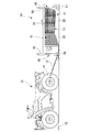
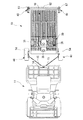
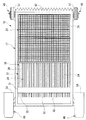
図1および図2に示すように、この実施形態のビーチクリーナー10は、牽引車両11により牽引されて走行しつつ砂地12のゴミ類を回収するものである。
【0020】
まず、牽引車両11について説明する。牽引車両11は、鞍乗り型の四輪車であり、後輪の車軸近傍に固定された牽引用部材14に二本のチェーン15の一端部がかけられ、これらチェーン15の他端部がビーチクリーナー10にかけられることで、該牽引車両11にビーチクリーナー10が連結される。ここで、二本のチェーン15のそれぞれの他端部は、車幅方向に間隔をあけるようにしてビーチクリーナー10に連結されており、しかも、そのときのチェーンラインは、後方に位置するほど下側に位置するように傾斜している。また、このチェーン15としては、前後左右上下のいずれの方向にも変形可能な連結部材であればよく、例えばチェーン15に換えてワイヤ等を用いることも可能である。なお、以下の説明において用いる前後は、進行方向における前後である。
【0021】
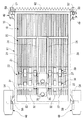
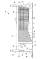
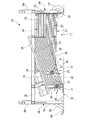
この実施形態のビーチクリーナー10は、図3〜図8等に示すように、ゴミ類を回収する略箱状の回収体17を有しており、この回収体17は、略水平に沿う底部形成部18と、該底部形成部18の車幅方向における両端の上側にそれぞれ設けられ鉛直かつ前後方向に延在する側部形成部19と、底部形成部18の後端部の上側に設けられ鉛直かつ車幅方向に延在する後部形成部20とを有している。
【0022】
底部形成部18は、図3および図4に示すように、前部に設けられ走行することにより前方のゴミ類をすくい上げる、前方側が下方に位置するように傾斜するスノコ状部22と、該スノコ状部22の後端部位置から後方側が下方に位置するように傾斜延在するスノコ状部23と有している。これらスノコ状部22,23は、中間部分で屈曲された鉄、ステンレスあるいはアルミニウム製の棒状部材24を、前後方向に延在させた状態で、それぞれの屈曲部を車幅方向に延在する支持棒部材21に支持させつつ車幅方向に等間隔で複数並列に配列してなるもので、支持棒部材21よりも前側がスノコ状部22となり、支持棒部材21よりも後側がスノコ状部23となる。ここで、隣り合う棒状部材24間の隙間間隔は略20mmとされている。なお、前側のスノコ状部22の水平に対する角度は、後側のスノコ状部23の水平に対する角度より大とされている。
【0023】
両側部形成部19は、図4に示すように、それぞれ、前側のスノコ状部22の略上側に、該スノコ状部22と平行をなして上下に等間隔で複数配列されるとともに、後側のスノコ状部23の略上側に、該スノコ状部23と略平行に略等間隔で複数配列される棒状部材25を有しており、スノコ状をなしている。両側部形成部19においても、略平行をなして隣り合う棒状部材25間の隙間間隔は略20mmとされている。
【0024】
後部形成部20は、底部形成部18の後端部に、該底部形成部18に垂直をなして車幅方向に等間隔で複数配列される図5に示す棒状部材26を有しており、スノコ状をなしている。この後部形成部20においても、隣り合う棒状部材26間の隙間間隔は略20mmとされている。
【0025】
そして、底部形成部18における後側のスノコ状部23の下側の全範囲からその上側の両側部形成部19の範囲にかけて、図6および図7に示すように、外側に網状体28が張られており、この網状体28によって、前側のスノコ状部22の後方に、後方側が下方に位置するように傾斜してゴミ類を保持する網状部29が形成されている。なお、この網状部29の隙間間隔は、スノコ状部22の隙間間隔と略同じとされている。また、後側のスノコ状部23と同じとなる網状部29の水平に対する角度は、前側のスノコ状部22の水平に対する角度より小となっている。ここで、上記網状体28をさらに後部形成部20に張ってもよい。
【0026】
なお、以上において、網状体28を張るのではなく、後側のスノコ状部23のかわりに、前側のスノコ状部22の後方を直接網状体で構成してもよく、これに加えて後側のスノコ状部23の上側の両側部形成部19を直接網状体で構成したり、さらに加えて後部形成部20を直接網状体で構成したりしてもよい。
【0027】
底部形成部18の前側のスノコ状部22の前部は、図3、図4および図8に示すように、略水平に沿いかつ車幅方向に延在する連結板部31とされており、該連結板部31に上記した棒状部材24のすべての前端部が固定されている。そして、この連結板部31には、複数が車幅方向に等間隔をあけて平行に配置されるとともに、それぞれ前方側が下方に位置するように傾斜しつつ前方に突出する棒状の爪部材32が固定されている。
【0028】
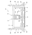
回収体17の車幅方向における中央には、図3および図4に示すように、前側のスノコ状部22の上側にこれと平行をなして二本の支持部材34が配設されており、これら支持部材34に、同形状の内燃機関35が二台、前後に位置をずらして取り付けられている。これら内燃機関35は、スノコ状部22と傾斜を合わせるようにして取り付けられている。これら内燃機関35は、それぞれスノコ状部22の方向に延出する延出部36を有しており、該延出部36の下部に、車幅方向に両側部形成部19の近傍位置まで延在する回転軸37を有していて、該回転軸37を回転させる。
【0029】
この回転軸37は、前側のスノコ状部22の上側に設けられるとともに該回転軸37を中心として下部が後方に移動するように回転することでゴミ類をスノコ状部22との間を通して後方に送り出す回転体39の一部を構成している。
【0030】
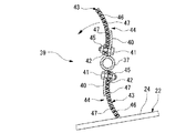
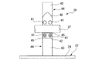
すなわち、回転体39は、図9および図10に示すように、上記した回転軸37に固定される鋼板からなる剛性部材40と、該剛性部材40に挿通されるボルト部材41と、固定されたナット部材45にボルト部材41を螺合させることで剛性部材40に連結される鋼板からなる支持板42と、ボルト部材41およびナット部材45の締結で剛性部材40と支持板42とに挟持固定される弾性部材43とからなる回転部44を有している。
【0031】
そして、回転体39は、この回転部44が回転軸37の軸線方向同位置に互いに反対方向に延出するように設けられたものの組を、回転軸37の軸線方向に等ピッチで、しかも回転方向における位置を徐々にずらすように位相を異ならせて配設することにより構成されている。すなわち、図3および図8に示すように、回転軸37の内燃機関35を中心とした両側部には、それぞれ、回転部44の組が複数(具体的には5組)設けられており、これらの組で360度を等分割するように、軸線方向における一側から順に略等角度ずつ同じ方向に角度をずらすようにして各組が設けられている。
【0032】
図9および図10に示すように、各回転部44を構成する弾性部材43は、略長方形状をなすもので、長手方向における一端部において剛性部材40および支持板42に固定されることにより、回転体39の半径方向における外部側を構成している。ここで、弾性部材43は、ゴム材46の内部に合成繊維や金属等からなる補強用の芯部材47が格子状に内蔵されてなるものである。そして、弾性部材43は、半径方向における外部側が回転方向先方側に位置するように湾曲しており、最もスノコ状部22側に位置するときに、該スノコ状部22に対し隙間が略0となる長さとされている。
【0033】
回転部44を構成する剛性部材40は、弾性部材43の長さの略1/3程度の長さのもので、弾性部材43の形状に合わせて、半径方向における外部側が回転方向先方側に位置するように湾曲しており、回転体44の半径方向における内部側において弾性部材43の一端部を回転部44の回転方向における後側から支持する。
【0034】
上記構成の回転体39が、二台の内燃機関35にそれぞれ設けられており、その結果、複数の回転体39が前後に位置をずらし、しかもスノコ状部22と傾斜を合わせて(複数の回転体39の中心同士を結んだ線がスノコ状部22と平行をなすようにして)、スノコ状部22の上側に配置されている。
【0035】
なお、両内燃機関35は、支持部材34に対し着脱可能かつスライド可能であり、砂質等に応じて、それぞれの固定位置を支持部材34上の任意の位置に設定可能となっている。ただし、このとき位置調整を行うのは、主として、最も前側の内燃機関35よりも後ろに配置されるものであり、最も前側の内燃機関35については、その回転軸37を連結板部31の略鉛直上方とする略一定位置に配置するのが好ましい。
【0036】
以上に述べた構成の回収体17の前端部および後端部それぞれの車幅方向両側には、該回収体17を支持するとともに砂地12に接地して走行する支持走行部48,49が取り付けられている。
【0037】
すなわち、図3に示すように、回収体17の前後左右の四隅には、角筒状の取付部材50が上下に開口するように固定されており、これら取付部材50には、図11および図12に示すように、車幅方向に貫通する貫通穴51がそれぞれ同高さ位置に形成されている。
【0038】
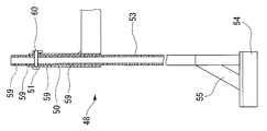
そして、図7等に示す前側の取付部材50に取り付けられる支持走行部48は、図12に示すように、取付部材50内に挿通される角筒状の支柱部53と、該支柱部53の下端部に水平方向に沿うよう固定された板状のスキー状部54と、支柱部53とスキー状部54との固定状態を補強する補強部55とを有している。ここで、スキー状部54は、その前端部が前側ほど上側に位置するように湾曲されている。なお、上記した牽引車両11に連結させるための二本のチェーン15は、各スキー状部54に連結される。
【0039】
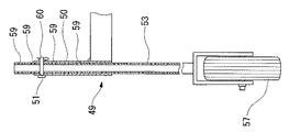
また、図7等に示す後側の取付部材50に取り付けられる支持走行部49は、図11に示すように、取付部材50内に挿通される上記と同様の支柱部53と、該支柱部53の下端部に水平軸回りに回転可能に支持された車輪57とを有している。なお、この車輪57は、回転軸線を常に車幅方向に沿わせるようになっている。
【0040】
ここで、支持走行部48,49のいずれにおいても、支柱部53には、図11および図12に示すように、車幅方向に貫通する貫通穴59が、高さ方向に等ピッチで複数形成されており、支柱部53の貫通穴59と取付部材50の貫通穴51とにピン部材60を挿通させることにより、支持走行部48,49は取付部材50に固定される一方、ピン部材60を抜くことで、支持走行部48,49は取付部材50に対し自由となり取り外しが可能となる(すなわち、支持走行部48,49は、回収体17の取付部材50に対し着脱可能とされている)。
【0041】
また、ピン部材60を抜いた状態で、支柱部53を取付部材50に対し高さ方向にずらすことで支持走行部48,49の回収体17に対する高さを調整し、その後一致する支柱部53の適宜の貫通穴59と取付部材50の貫通穴51とにピン部材60を挿通させて、支持走行部48,49を回収体17に対し固定することで、支持走行部48,49の回収体17に対する高さが調整される(すなわち、支持走行部48,49は、回収体17に対し高さ調整可能とされている)。
【0042】
図3〜図6に示すように、回収体17の後部形成部20の後側すなわち最後端部には、走行時に砂地12を均す仕上部材62が車幅方向に延在するように固定されている。この仕上部材62は、ゴム板等の弾性部材からなるもので、下部側が後方に位置するように湾曲する形状をなしている。そして、この仕上部材62の下端部は、同一形状の山型が車幅方向に連続的に多数配設された形状をなしており、その結果、砂地12に均一な深さの溝模様をえがくようになっている。なお、仕上部材62の下端部は、このように山型とする以外に波型や凹凸型とすることが可能であり、またいずれの場合も配設ピッチの大小を換えたりすることができる。
【0043】
そして、この実施の形態のビーチクリーナー10を両内燃機関35で両回転体39を駆動状態として、牽引車両11で牽引することで走行させる。すると、ビーチクリーナー10のスノコ状部22の前端部に設けられた複数の爪部材32が砂地12に入り込み、砂地12上あるいは砂地12に多少入り込んだゴミ類を、上側にかき上げ該爪部材32に連続するスノコ状部22に走行の勢いですくい上げさせることになる。そして、スノコ状部22にすくい上げられたゴミ類は、砂とともに前側の回転体39で後方に送り出されるが、このときゴミ類のみが回転体39とスノコ状部22との間を通りスノコ状部22の傾斜を登るようにして後方に送り出され、砂はスノコ状部22の隙間を介してスノコ状部22と網状部29と砂地12とで囲まれる略三角形状の空間を介して砂地12に落下することになる。そして、上記のようにして前側の回転体39でスノコ状部22に沿って後方に送り出されることにより砂と分離されたゴミ類が、さらに、後側の回転体39で該回転体39とスノコ状部22との間を通りスノコ状部22の傾斜を登るようにして後方に送り出され、後方が下側に傾斜する網状部29に至って該網状部29により保持されることになる。
【0044】
そして、爪部材32でかき上げられた砂およびスノコ状部22から落下した砂を含む砂地12は、最後にビーチクリーナー10の後端部の仕上部材62で均される。
【0045】
以上に述べた本実施形態のビーチクリーナー10によれば、複数が車幅方向に間隔をあけて配置されるとともに前方側が下方に位置するように傾斜しつつ前方に突出する爪部材32と、走行することにより前方のゴミ類をすくい上げる前方側が下方に位置するように傾斜するスノコ状部22と、該スノコ状部22の上側に設けられてゴミ類をスノコ状部22との間を通して後方に送り出す回転体39と、スノコ状部22の後方に設けられてゴミ類を保持する後方側が下方に位置するように傾斜する網状部29とを有しているため、牽引車両11で牽引されて走行することにより爪部材32が砂地12に入り込んで、ゴミ類をかき上げてスノコ状部22にすくい上げさせることになり、ゴミ類がスノコ状部22に乗り上げる一方、ゴミ類とともにすくい上げられる砂はスノコ状部22の隙間を介して落下することになる。そして、スノコ状部22に乗り上げたゴミ類は、該スノコ状部22の上に配置された複数の回転体39でスノコ状部22との間を通して後方に送り出され網状部29で保持されることになる。
【0046】
このように、前方側が下方に位置するように傾斜するスノコ状部22でゴミ類と砂とを分離しつつゴミ類のみを回転体39で後方の網状部29に送り出す構成であるため、小型にでき、しかも簡素な構造にできる。加えて、網状部29が後方側が下方に位置するように傾斜しているため、ここに保持するゴミ類が前方のスノコ状部22に移動してしまうことがなく、ゴミ類を確実に保持することができる。加えて、爪部材32が砂地12に入り込んでゴミ類をかき上げてスノコ状部22にすくい上げさせるため、砂を極力動かさずにすみ、その結果、牽引車両11の負荷を小さくできる上、砂埃を低減できる。
【0047】
また、回転体39は、複数がスノコ状部22の傾斜にあわせて配置されているため、ゴミ類と砂との分離を確実にするためスノコ状部22の長さをながくしても、ゴミ類を順次回転体39で後方に送り出し、網状部29に保持させることができる。
【0048】
さらに、回転体39の半径方向における外部側に変形容易な弾性部材43が設けられているため、回転体39の回転でスノコ状部22との間を通してゴミ類を後方に送り出す際に、弾性部材43がゴミ類の大きさに応じて変形することになる。したがって、ゴミ類を無理なく確実に後方に送り出すことができる。特に、硬く大きいゴミ類を後方に送り出す場合に、弾性部材43が変形して逃げることで回転体39がストールするのを防止できる。
【0049】
しかも、弾性部材43内には補強用の芯部材47が内蔵されているため、その強度が向上することになる。
【0050】
その上、回転体39が半径方向における内部側に弾性部材43を支持する剛性部材40を有しているため、弾性部材43が剛性部材40によって支持されることで、その根元部分の強度が確実に向上することになる。
【0051】
さらに、弾性部材43はその半径方向における外部側が回転方向先方側に位置するように湾曲しているため、スノコ状部22との間を通してゴミ類を後方に送り出す際に、ゴミ類をより確実に後方に送り出すことができる。
【0052】
加えて、回転体39はスノコ状部22に対し隙間が略0とされているため、比較的小さなゴミ類をも確実にスノコ状部22との間を通して後方に送り出すことができる。
【0053】
また、スノコ状部22の隙間間隔と網状部29の隙間間隔とを略同じとすることで、スノコ状部22ですくい上げたゴミ類を網状部29で確実に保持することができる。
【0054】
さらに、スノコ状部22の隙間間隔は略20mmとされているため、ゴミ類として最も多い空き缶やペットボトル、その蓋等を確実に回収することができる。
【0055】
また、回収体17を支持するとともに砂地12に接地して走行する支持走行部48が、回収体17の前側下部に、水平方向に沿う板状のスキー状部54を具備するため、走行方向の前側下部にあって砂地12に沈み込みやすい部分を板状のスキー状部54とし、面で走行し面圧を小さくすることによって、砂地12へ深く沈み込んでしまうことを防止する。したがって、走行中に砂地12に深く沈み込んでしまうことを防止することにより、牽引車両11への走行抵抗を低減でき、しかも砂地12に対する回収体17の高さを安定させることができるため、作業効率を大幅に向上させることができる。
【0056】
さらに、支持走行部48,49が、回収体17の取付部材50に対し高さ調整可能とされているため、砂地12の質により支持走行部48,49の沈み込み量が変化しても、回収体17の高さをゴミ類の回収に最適な高さに調整することができる。したがって、効率よくゴミ類を回収することができる。
【0057】
加えて、支持走行部48,49が、回収体17の取付部材50に対し着脱可能とされているため、前側の取付部材50に上記スキー状部54を有する支持走行部48を取り付ければ、上記のように支持走行部48が砂地12へ深く沈み込むことを防止でき、他方、図13に示すように、後側の取付部材50の支持走行部49はそのままで、前側の取付部材50に、支柱部53の下端に水平旋回可能な車輪57を有する支持走行部63を取り付け、しかも回収体17が接地面64より高くなるようにその支持走行部49,63に対する高さを調整すれば、四隅がすべて車輪57となって砂地12以外の路面での走行に対応可能となる。したがって、容易に砂地12までの舗装面等を運搬することができる。逆に、前側の取付部材50の支持走行部48はそのままで、後側の取付部材50に、スキー状部54を有する支持走行部48を用いれば、四隅がすべてスキー状部54となって特に柔らかい砂地12等の走行に対応可能となる。
【0058】
加えて、牽引車両11とビーチクリーナー10とを連結させるために上記したチェーン15やワイヤのように前後左右上下のいずれの方向にも変形可能な部材を用いることで、牽引車両11のみの後退が可能になるとともに、ビーチクリーナー10の路面追従性を高めることができる。また、二本のチェーン15を車幅方向に間隔をあけるようにしてビーチクリーナー10側に連結させているため、ビーチクリーナー10の走行時の方向性を安定させることが可能となり操縦者の狙いとする作業ラインを移動させることが可能となる。更に、チェーンラインを、後方に向かってやや下向きとしているため、牽引抵抗も低下し、円滑な作業が可能となる。
【0059】
さらに、スノコ状部22が後側が上側に位置するように傾斜するとともに網状部29が後側が下側に位置するように傾斜し、よって、スノコ状部22と網状部29と砂地12とで略三角形状の空間を形成することになるため、スノコ状部22でゴミとともにすくい上げられた砂を円滑にスノコ状部22の隙間から砂地12に落下させることができるとともに、ビーチクリーナー10の全体の重量増加を抑え、スタック等を生じることなく円滑で連続的な牽引作業が可能となる。
【0060】
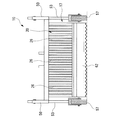
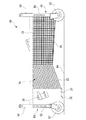
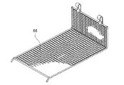
なお、上記網状体28を設けず、かつ後側のスノコ状部22および後部形成部20に換えて、図14および図15に示すように、L型の網状体66を着脱自在に設けてもよい。このように構成すれば、この網状体66を取り外すだけでゴミ類を一度に排除でき、ゴミメンテ性が向上する。
【0061】
【発明の効果】
以上詳述したように、本発明の請求項1記載のビーチクリーナーによれば、走行することにより前方のゴミ類をすくい上げるスノコ状部と、該スノコ状部の上側に設けられてゴミ類をスノコ状部との間を通して後方に送り出す回転体とを具備するため、牽引車両で牽引されて走行することにより前方のゴミ類をスノコ状部ですくい上げると、ゴミ類はスノコ状部に乗り上げる一方、ゴミ類とともにすくい上げられる砂はスノコ状部の隙間を介して落下することになる。そして、スノコ状部に乗り上げたゴミ類は、回転体でスノコ状部との間を通して後方に送り出されることになる。
【0062】
このように、スノコ状部でゴミ類と砂とを分離しつつゴミ類のみを回転体で後方に送り出す構成であるため、小型にでき、しかも簡素な構造にできる。
【0063】
さらに、回転体の半径方向における外部側に弾性部材が設けられているため、回転体の回転でスノコ状部との間を通してゴミ類を後方に送り出す際に、弾性部材がゴミ類の大きさに応じて変形することになる。
【0064】
したがって、ゴミ類を無理なく確実に後方に送り出すことができる。
【0065】
また、上記弾性部材内には補強用の芯部材が内蔵されているため、その強度が向上することになる。
【0066】
本発明の請求項2記載のビーチクリーナーによれば、回転体が半径方向における内部側に弾性部材を支持する剛性部材を有しているため、弾性部材が剛性部材によって支持されることで、その根元部分の強度が確実に向上することになる。
【0067】
本発明の請求項3記載のビーチクリーナーによれば、弾性部材はその半径方向における外部側が回転方向先方側に位置するように湾曲しているため、スノコ状部との間を通してゴミ類を後方に送り出す際に、ゴミ類をより確実に後方に送り出すことができる。
【0068】
本発明の請求項4記載のビーチクリーナーによれば、回転体はスノコ状部に対し隙間が略0とされているため、比較的小さなゴミ類をも確実にスノコ状部との間を通して後方に送り出すことができる。
【図面の簡単な説明】
【図1】 本発明の一実施形態のビーチクリーナーおよび牽引車両を示す側面図である。
【図2】 本発明の一実施形態のビーチクリーナーおよび牽引車両を示す平面図である。
【図3】 本発明の一実施形態のビーチクリーナーを示す平面図である。
【図4】 本発明の一実施形態のビーチクリーナーを示す側断面図である。
【図5】 本発明の一実施形態のビーチクリーナーを示す後面図である。
【図6】 本発明の一実施形態のビーチクリーナーを示す底面図である。
【図7】 本発明の一実施形態のビーチクリーナーを示す側面図である。
【図8】 本発明の一実施形態のビーチクリーナーを示す正面図である。
【図9】 本発明の一実施形態のビーチクリーナーの回転体の一部を示す側断面図である。
【図10】 本発明の一実施形態のビーチクリーナーの回転体の一部を示す正面図である。
【図11】 本発明の一実施形態のビーチクリーナーの一の支持走行部等を示す一部を断面とした正面図である。
【図12】 本発明の一実施形態のビーチクリーナーの別の支持走行部等を示す一部を断面とした正面図である。
【図13】 本発明の一実施形態のビーチクリーナーの別の状態を示す側面図である。
【図14】 本発明の一実施形態のビーチクリーナーの変形例を示す側断面図である。
【図15】 本発明の一実施形態のビーチクリーナーの変形例に用いられる網状体を示す斜視図である。
【符号の説明】
10 ビーチクリーナー
11 牽引車両
22 スノコ状部
37 回転軸
39 回転体
40 剛性部材
43 弾性部材
47 芯部材[0001]
BACKGROUND OF THE INVENTION
The present invention relates to a beach cleaner used when cleaning a sandy beach such as a beach.
[0002]
[Prior art]
Japanese Patent Laid-Open No. 7-224413 discloses a beach cleaner used when collecting garbage such as empty cans, PET bottles, their lids, and wood chips scattered on sandy beaches such as beaches . This beach cleaner collects trash while traveling by being pulled by a towing vehicle, and digs up sand together with trash by an excavation roller provided in front, and transfers the trash on the rear side as it travels. The waste is received by the device, and the waste transporting device separates the waste and the sand so that only the waste is accommodated in the waste storage portion.
[0003]
Another beach cleaner is disclosed in Japanese Patent Laid-Open No. 3-138203. This beach cleaner is a self-propelled type that scoops up trash mixed with sand and conveys it with a belt conveyor, and separates and collects trash using sand as a meanwhile.
[0004]
[Problems to be solved by the invention]
By the way, the beach cleaner disclosed in Japanese Patent Application Laid-Open No. 7-224413 is provided with a drilling roller for digging sand together with garbage at the front, and the garbage and sand digged up according to traveling are behind it. Since it has the garbage transfer conveyance part which receives and isolate | separates, there existed a problem that it became a large thing as a whole and the structure became complicated.
[0005]
In addition, what is disclosed in the above-mentioned Japanese Patent Application Laid-Open No. 3-138203 also scoops up trash mixed with sand together with the sand, conveys it with a belt conveyor, and separates the sand from the trash. However, the structure becomes complicated and the structure becomes complicated.
[0006]
Accordingly, an object of the present invention is to provide a beach cleaner that can be downsized and has a simple structure.
[0007]
[Means for Solving the Problems]
In order to achieve the above object, a beach cleaner according to claim 1 of the present invention collects garbage while traveling while being pulled by a tow vehicle (for example, the
[0008]
Thus, to provide a slat-like portion that scoops up the front garbage by traveling, and a rotating body that is provided on the upper side of the slat-like portion and feeds the garbage back between the slat-like portion, When scooping up the trash in front of the slat-like part by running by being pulled by a towing vehicle, the trash will ride on the slat-like part, while the sand scooped up with the trash will fall through the gap of the slat-like part become. And the garbage which got on the snowboard-like part will be sent out through the space between the snowboard-like part by the rotating body.
[0010]
AlsoSince the elastic member is provided on the outer side in the radial direction of the rotating body, the elastic member depends on the size of the garbage when the rotating body rotates to send the garbage backward through the slat-like portion. Will be deformed.
[0012]
furtherSince the reinforcing core member is built in the elastic member, the strength is improved.
[0013]
Claims of the invention2The listed beach cleaner claims1With respect to what is described, the rotating body has a rigid member (for example, the
[0014]
Thus, since the rotating body has a rigid member that supports the elastic member on the inner side in the radial direction, the strength of the root portion is reliably improved by the elastic member being supported by the rigid member. become.
[0015]
Claims of the invention3The listed beach cleaner claims1 or 2With respect to what is described, the elastic member is characterized in that it is curved so that the outer side in the radial direction is located on the front side in the rotational direction.
[0016]
In this way, the elastic member is curved so that the outer side in the radial direction is positioned on the front side in the rotational direction, so that when the garbage is sent backward through the slat-shaped portion, the garbage is more reliably collected. Can be sent backwards.
[0017]
Claims of the invention4The beach cleaner according to claim 1 to claim 1.3With respect to the structure according to any one of the above, the rotating body is characterized in that a gap is substantially zero with respect to the slat-shaped portion.
[0018]
As described above, since the clearance is substantially zero with respect to the slat-like portion, relatively small dust can be reliably sent back through the slat-like portion.
[0019]
DETAILED DESCRIPTION OF THE INVENTION
A beach cleaner according to an embodiment of the present invention will be described below with reference to the drawings.
As shown in FIGS. 1 and 2, the
[0020]
First, the
[0021]
As shown in FIGS. 3 to 8 and the like, the
[0022]
As shown in FIGS. 3 and 4, the bottom
[0023]
As shown in FIG. 4, a plurality of the side
[0024]
The rear
[0025]
Then, as shown in FIG. 6 and FIG. 7, a net-
[0026]
In the above description, the
[0027]
As shown in FIGS. 3, 4 and 8, the front part of the slat-
[0028]
In the center of the
[0029]
The rotating
[0030]
That is, as shown in FIGS. 9 and 10, the rotating
[0031]
The rotating
[0032]
As shown in FIGS. 9 and 10, the
[0033]
The
[0034]
The rotating
[0035]
Both the
[0036]
On both sides in the vehicle width direction of the front end portion and the rear end portion of the
[0037]
That is, as shown in FIG. 3, square
[0038]
7 and the like, the
[0039]
Further, as shown in FIG. 11, the
[0040]
Here, as shown in FIGS. 11 and 12, in both the
[0041]
Further, with the
[0042]
As shown in FIGS. 3 to 6, a finishing
[0043]
Then, the
[0044]
And the
[0045]
According to the
[0046]
In this way, the configuration is such that only the garbage is sent out to the rear net-
[0047]
Further, since a plurality of the
[0048]
Further, since the
[0049]
In addition, since the reinforcing
[0050]
In addition, since the rotating
[0051]
Further, since the
[0052]
In addition, since the gap between the
[0053]
Further, by making the gap interval of the slat-
[0054]
Furthermore, since the clearance gap between the slat-
[0055]
In addition, the
[0056]
Furthermore, since the
[0057]
In addition, since the
[0058]
In addition, in order to connect the
[0059]
Further, the slat-
[0060]
Note that the net-
[0061]
【The invention's effect】
As described above in detail, according to the beach cleaner of the first aspect of the present invention, the snowboard-shaped portion that scoops up the front garbage by running and the dust disposed on the upper side of the snowboard-shaped portion. Since it has a rotating body that feeds it back through the space between the two parts, when it is pulled by the towing vehicle and scoops up the trash in front of the sword-like part, Sand that is scooped up together with the earth will fall through the gaps in the snowboard-like part. And the garbage which got on the snowboard-like part will be sent out through the space between the snowboard-like part by the rotating body.
[0062]
Thus, since it is the structure which sends out only garbage with a rotary body, separating garbage and sand with a slat-like part, it can be reduced in size and can also be made a simple structure.
[0063]
furtherSince the elastic member is provided on the outer side in the radial direction of the rotating body, the elastic member depends on the size of the garbage when the rotating body rotates to send the garbage backward through the slat-like portion. Will be deformed.
[0064]
Therefore, it is possible to reliably send out the garbage backward without difficulty.
[0065]
Also, aboveSince the reinforcing core member is built in the elastic member, the strength is improved.
[0066]
Claims of the invention2According to the described beach cleaner, since the rotating body has the rigid member that supports the elastic member on the inner side in the radial direction, the elastic member is supported by the rigid member, so that the strength of the root portion is ensured. Will be improved.
[0067]
Claims of the invention3According to the described beach cleaner, the elastic member is curved so that the outer side in the radial direction is located on the front side in the rotation direction. Can be sent back more reliably.
[0068]
Claims of the invention4According to the described beach cleaner, since the gap between the rotator and the slat-like portion is substantially zero, relatively small dust can be reliably sent out through the slat-like portion.
[Brief description of the drawings]
FIG. 1 is a side view showing a beach cleaner and a towing vehicle according to an embodiment of the present invention.
FIG. 2 is a plan view showing a beach cleaner and a towing vehicle according to an embodiment of the present invention.
FIG. 3 is a plan view showing a beach cleaner according to an embodiment of the present invention.
FIG. 4 is a side sectional view showing a beach cleaner according to an embodiment of the present invention.
FIG. 5 is a rear view showing the beach cleaner according to the embodiment of the present invention.
FIG. 6 is a bottom view showing a beach cleaner according to an embodiment of the present invention.
FIG. 7 is a side view showing a beach cleaner according to an embodiment of the present invention.
FIG. 8 is a front view showing a beach cleaner according to an embodiment of the present invention.
FIG. 9 is a side sectional view showing a part of a rotating body of a beach cleaner according to an embodiment of the present invention.
FIG. 10 is a front view showing a part of the rotating body of the beach cleaner according to the embodiment of the present invention.
FIG. 11 is a front view, partly in section, showing a supporting traveling portion and the like of one of the beach cleaners according to one embodiment of the present invention.
FIG. 12 is a front view, partly in section, showing another support running portion and the like of the beach cleaner according to one embodiment of the present invention.
FIG. 13 is a side view showing another state of the beach cleaner according to the embodiment of the present invention.
FIG. 14 is a side sectional view showing a modification of the beach cleaner according to the embodiment of the present invention.
FIG. 15 is a perspective view showing a mesh body used in a modification of the beach cleaner according to one embodiment of the present invention.
[Explanation of symbols]
10 Beach cleaner
11 Towing vehicle
22 Snowboard-shaped part
37 axis of rotation
39 Rotating body
40 Rigid member
43 Elastic member
47 Core member
Claims (4)
走行することにより前方のゴミ類をすくい上げるスノコ状部と、該スノコ状部の上側に設けられるとともに車幅方向に延在する回転軸を中心として下部が後方に移動するように回転することでゴミ類を前記スノコ状部との間を通して後方に送り出す回転体とを具備し、
前記回転体には、半径方向における外部側に弾性部材が設けられているとともに該弾性部材内には補強用の芯部材が内蔵されていることを特徴とするビーチクリーナー。A beach cleaner that collects garbage while being towed by a tow vehicle,
A sword-like portion that scoops up front garbage by traveling, and a trash by rotating so that the lower part moves rearward about a rotation axis that is provided above the snouce-like portion and extends in the vehicle width direction A rotating body that sends out the rear through the gap between the slat-like parts ,
The beach cleaner according to claim 1, wherein an elastic member is provided on the outer side of the rotating body in a radial direction, and a reinforcing core member is built in the elastic member .
Priority Applications (4)
| Application Number | Priority Date | Filing Date | Title |
|---|---|---|---|
| JP2000308497A JP3662829B2 (en) | 2000-10-06 | 2000-10-06 | Beach cleaner |
| US09/969,652 US6640906B2 (en) | 2000-10-06 | 2001-10-04 | Beach cleaner |
| BRPI0104429-0A BR0104429B1 (en) | 2000-10-06 | 2001-10-04 | beach cleaner. |
| FR0112842A FR2815058B1 (en) | 2000-10-06 | 2001-10-05 | BEACH CLEANING DEVICE |
Applications Claiming Priority (1)
| Application Number | Priority Date | Filing Date | Title |
|---|---|---|---|
| JP2000308497A JP3662829B2 (en) | 2000-10-06 | 2000-10-06 | Beach cleaner |
Publications (2)
| Publication Number | Publication Date |
|---|---|
| JP2002115233A JP2002115233A (en) | 2002-04-19 |
| JP3662829B2 true JP3662829B2 (en) | 2005-06-22 |
Family
ID=18788796
Family Applications (1)
| Application Number | Title | Priority Date | Filing Date |
|---|---|---|---|
| JP2000308497A Expired - Fee Related JP3662829B2 (en) | 2000-10-06 | 2000-10-06 | Beach cleaner |
Country Status (4)
| Country | Link |
|---|---|
| US (1) | US6640906B2 (en) |
| JP (1) | JP3662829B2 (en) |
| BR (1) | BR0104429B1 (en) |
| FR (1) | FR2815058B1 (en) |
Families Citing this family (13)
| Publication number | Priority date | Publication date | Assignee | Title |
|---|---|---|---|---|
| US7156236B2 (en) * | 2004-02-26 | 2007-01-02 | Rockland, Inc. | Machine for removing articles deposited on the ground |
| US7104338B1 (en) | 2005-07-29 | 2006-09-12 | Mcfarland David L | Sweeper chain support system |
| US7568300B1 (en) | 2005-07-29 | 2009-08-04 | Mcfarland David L | Combination support stand and bucket locking system |
| US7491027B1 (en) | 2005-07-29 | 2009-02-17 | Mcfarland David L | Pivoting loader attachment system |
| US7597154B1 (en) | 2005-07-29 | 2009-10-06 | Mcfarland David L | Torque tube with slide out cage system |
| US7506692B2 (en) | 2005-11-30 | 2009-03-24 | H. Barber And Sons, Inc. | Tine raking device |
| US20120103876A1 (en) * | 2010-10-27 | 2012-05-03 | Rb Environmental, L.L.C. | Sand Sifter |
| US9297132B2 (en) | 2013-11-26 | 2016-03-29 | Wd Thompson Inc. | Turtle friendly beach cleaning device |
| CN107135686B (en) * | 2017-06-05 | 2023-12-19 | 新疆农垦科学院 | A friction-type flexible automatic film stripping and residual film recovery machine before sowing |
| US11697126B2 (en) | 2019-11-21 | 2023-07-11 | Technologie Hoola One Inc. | Granular litter cleaning apparatus and process |
| US11598062B2 (en) * | 2020-02-18 | 2023-03-07 | Devin ARCHIBALD | Method and apparatus for collecting objects from a surface |
| USD1037856S1 (en) | 2021-08-27 | 2024-08-06 | Berry Global, Inc. | Container |
| MX2024002545A (en) * | 2021-08-27 | 2024-05-31 | Berry Global Inc | Sortation-friendly container and method. |
Family Cites Families (30)
| Publication number | Priority date | Publication date | Assignee | Title |
|---|---|---|---|---|
| US1313053A (en) * | 1919-08-12 | Peanut-harvester | ||
| US1288559A (en) * | 1918-03-13 | 1918-12-24 | Herman J Genske | Thistle-puller. |
| US1425976A (en) * | 1921-07-19 | 1922-08-15 | Kent Budd | Clod crusher |
| US1578600A (en) * | 1923-08-29 | 1926-03-30 | Greatrix Henry | Combined stone and root gatherer |
| US2296851A (en) * | 1941-02-11 | 1942-09-29 | John F Henry | Road machine |
| US2534405A (en) * | 1945-12-10 | 1950-12-19 | Clifton H Bradley | Peanut harvester |
| US2744739A (en) * | 1953-04-27 | 1956-05-08 | Joseph C Evans | Beach sand cleaning device |
| US2990019A (en) * | 1958-08-22 | 1961-06-27 | Finn Equipment Company | Litter cleaning apparatus |
| US3316977A (en) * | 1964-04-15 | 1967-05-02 | Allis Chalmers Mfg Co | Screen conveyor with ground engaging scoop |
| US3596717A (en) * | 1969-09-29 | 1971-08-03 | Valdemar Knudsen | Beach-cleaning vehicle |
| US4014390A (en) * | 1974-02-13 | 1977-03-29 | Teixeira Antone S | Beach cleaner apparatus |
| US4050518A (en) * | 1976-07-01 | 1977-09-27 | Gilmour Richard C | Beach cleaning apparatus |
| CH618138A5 (en) * | 1977-04-28 | 1980-07-15 | Habasit Ag | |
| US4167975A (en) * | 1977-09-08 | 1979-09-18 | Fahrenholz Harley D | Beach cleaning apparatus |
| US4241792A (en) * | 1979-01-15 | 1980-12-30 | Kratzer Donald K | Tractor drawn ground sweeper |
| DE3147650A1 (en) * | 1981-12-02 | 1983-06-09 | Günter 7913 Senden Holitschke | Method and device for cleaning sandy areas |
| US4608725A (en) * | 1985-02-21 | 1986-09-02 | Proficient Systems, Inc. | Litter retrieving machine |
| DE8806463U1 (en) * | 1988-05-17 | 1989-09-14 | Oel-Nolte Handelsgesellschaft mbH & Co KG, 5870 Hemer | Device for superficial cleaning of sandy soils |
| ES2007927A6 (en) * | 1988-06-15 | 1989-07-01 | Rombex Sa | Sand cleaning and stone removing machine. |
| JP3102002B2 (en) | 1989-03-23 | 2000-10-23 | 松下電器産業株式会社 | Hydrogen storage electrode and method for producing the same |
| JP2774561B2 (en) * | 1989-03-31 | 1998-07-09 | 松山株式会社 | Beach cleaner |
| JPH0657561B2 (en) * | 1989-09-14 | 1994-08-03 | 株式会社クボタ | Beach cleaner |
| JPH0657563B2 (en) | 1989-10-20 | 1994-08-03 | 株式会社クボタ | Beach cleaner |
| US5247717A (en) * | 1989-10-23 | 1993-09-28 | Owen Smith | Debris/litter collecting apparatus |
| US5133413A (en) * | 1990-01-30 | 1992-07-28 | Baxter Randall K | Beach cleaning apparatus |
| FR2661700B1 (en) * | 1990-05-03 | 1992-08-21 | F Tec | MOBILE EQUIPMENT FOR CLEANING SAND LAND. |
| JP2772236B2 (en) | 1994-02-14 | 1998-07-02 | 中小企業事業団 | Beach cleaning work vehicle |
| JP3138203B2 (en) | 1996-01-26 | 2001-02-26 | 東光株式会社 | Reference voltage generation circuit |
| DE19751244A1 (en) * | 1997-11-19 | 1999-05-20 | Artemis Kautschuk Kunststoff | Revolving inclined conveyor for potato harvesters and other agricultural machines |
| JP2002115234A (en) * | 2000-10-06 | 2002-04-19 | Honda Motor Co Ltd | Beach cleaner |
-
2000
- 2000-10-06 JP JP2000308497A patent/JP3662829B2/en not_active Expired - Fee Related
-
2001
- 2001-10-04 US US09/969,652 patent/US6640906B2/en not_active Expired - Fee Related
- 2001-10-04 BR BRPI0104429-0A patent/BR0104429B1/en not_active IP Right Cessation
- 2001-10-05 FR FR0112842A patent/FR2815058B1/en not_active Expired - Fee Related
Also Published As
| Publication number | Publication date |
|---|---|
| JP2002115233A (en) | 2002-04-19 |
| BR0104429B1 (en) | 2010-02-09 |
| BR0104429A (en) | 2002-06-04 |
| FR2815058B1 (en) | 2005-08-05 |
| US6640906B2 (en) | 2003-11-04 |
| FR2815058A1 (en) | 2002-04-12 |
| US20020040792A1 (en) | 2002-04-11 |
Similar Documents
| Publication | Publication Date | Title |
|---|---|---|
| JP3662829B2 (en) | Beach cleaner | |
| JP5018714B2 (en) | Beach cleaner trailer | |
| JP4476520B2 (en) | Beach cleaner | |
| US8720594B2 (en) | Beach cleaner | |
| US6857479B2 (en) | Beach cleaner | |
| JP2002115229A (en) | Beach cleaner | |
| US7896094B2 (en) | Beach cleaner | |
| JP5315462B2 (en) | Beach cleaner | |
| JP2002178824A (en) | Beach cleaner | |
| JP5226812B2 (en) | Beach cleaner | |
| JP2002115230A (en) | Beach cleaner | |
| US7798240B2 (en) | Waste recovery station structure for beach cleaner and beach cleaner structure | |
| JP2002115228A (en) | Beach cleaner | |
| JP4476966B2 (en) | Garbage collection station structure for beach cleaner | |
| JP4545706B2 (en) | Beach cleaner | |
| JP4531716B2 (en) | Garbage collection station for beach cleaner | |
| JP5018717B2 (en) | Beach cleaner | |
| JP4476959B2 (en) | Beach cleaner structure | |
| JP2002115226A (en) | Beach cleaner |
Legal Events
| Date | Code | Title | Description |
|---|---|---|---|
| A131 | Notification of reasons for refusal |
Free format text: JAPANESE INTERMEDIATE CODE: A131 Effective date: 20041116 |
|
| A521 | Written amendment |
Free format text: JAPANESE INTERMEDIATE CODE: A523 Effective date: 20041220 |
|
| TRDD | Decision of grant or rejection written | ||
| A01 | Written decision to grant a patent or to grant a registration (utility model) |
Free format text: JAPANESE INTERMEDIATE CODE: A01 Effective date: 20050315 |
|
| A61 | First payment of annual fees (during grant procedure) |
Free format text: JAPANESE INTERMEDIATE CODE: A61 Effective date: 20050324 |
|
| R150 | Certificate of patent or registration of utility model |
Free format text: JAPANESE INTERMEDIATE CODE: R150 |
|
| FPAY | Renewal fee payment (event date is renewal date of database) |
Free format text: PAYMENT UNTIL: 20080401 Year of fee payment: 3 |
|
| FPAY | Renewal fee payment (event date is renewal date of database) |
Free format text: PAYMENT UNTIL: 20090401 Year of fee payment: 4 |
|
| FPAY | Renewal fee payment (event date is renewal date of database) |
Free format text: PAYMENT UNTIL: 20090401 Year of fee payment: 4 |
|
| FPAY | Renewal fee payment (event date is renewal date of database) |
Free format text: PAYMENT UNTIL: 20100401 Year of fee payment: 5 |
|
| FPAY | Renewal fee payment (event date is renewal date of database) |
Free format text: PAYMENT UNTIL: 20110401 Year of fee payment: 6 |
|
| LAPS | Cancellation because of no payment of annual fees |