JP3662819B2 - Alarm collection / device control communication system and method - Google Patents
Alarm collection / device control communication system and method Download PDFInfo
- Publication number
- JP3662819B2 JP3662819B2 JP2000203006A JP2000203006A JP3662819B2 JP 3662819 B2 JP3662819 B2 JP 3662819B2 JP 2000203006 A JP2000203006 A JP 2000203006A JP 2000203006 A JP2000203006 A JP 2000203006A JP 3662819 B2 JP3662819 B2 JP 3662819B2
- Authority
- JP
- Japan
- Prior art keywords
- data
- communication
- communication device
- communication devices
- control
- Prior art date
- Legal status (The legal status is an assumption and is not a legal conclusion. Google has not performed a legal analysis and makes no representation as to the accuracy of the status listed.)
- Expired - Fee Related
Links
Images


Description
【0001】
【発明の属する技術分野】
本発明は警報収集・機器制御用通信システム及びその方法に関し、特に警報収集と機器制御とのために用いられる通信方法に関する。
【0002】
【従来の技術】
従来、警報収集と機器制御とに用いられる通信システムとしては、一般的に、イーサネットやトークンリング等に代表されるLAN(Local Area Network)によってビルや工場内に構築されるものがある。しかしながら、近年、このようなLAN構築の需要が高まる中、古いビルや既存の家屋へLANを新たに敷設するケースも増加している。
【0003】
また、比較的大きな設備投資を要する上記の一般的なLANに対して、LANほどの高速なデータ転送を必要とせず、小容量のデータ、例えば警報データや制御データ等を集中管理室で監視して制御することができる廉価な通信設備の構築要求がある。
【0004】
この要請に応えるために、例えば通信システム上に接続されている通信端末に予め固有のアドレスを設け、親装置からの目的アドレスに対してのみ当該端末装置の状態をレポートとして返信を返すような手法が提案されている。この手法については、特開平04−275798号公報(第1の公報)に開示されている。
【0005】
また、ネットワーク上のブランチをブランチリピータなる装置を用いてネットワークの利用網を分けるという方式もある。この方式については、特開昭58−081360号公報(第2の公報)に開示されている。
【0006】
【発明が解決しようとする課題】
上述した従来の通信システムでは、第1の公報に開示された手法を用いる場合、システム設置の段階から個々の通信端末に対してそれぞれ固有のアドレスを割り当てる初期設定の手順を有している。このため、運用途中において通信端末の増減が発生した場合、アドレスの割り当てを実施するために、通信端末と親装置との両方に対してアドレス管理の情報を提供する必要が生じる。
【0007】
その結果、通信端末の設置工事には個々の通信端末に対して、その必要数分のアドレスを設定しなければならず、大変な時間と労力とを要してしまうという問題がある。
【0008】
また、第2の公報に開示された手法を用いる場合には、ネットワーク中を伝送するデータをブランチリピータを用いてどのブランチに必要であるか否かを識別することから、各ブランチリピータにはブランチ毎に適合または不適合の行き先アドレスを覚えておくテーブルが必要となる。
【0009】
よって、必然的にブランチが多く、また個々のブランチ上の通信端末が多ければ、その数だけテーブルも大きくなり、ハードウェアで構築する際にはメモリ容量の増大を誘引するという問題がある。つまり、イーサネットやトークンリンクのように比較的大きな設備投資を前提とした場合、上記の手法は有効な手段であるが、小容量のデータ、例えば警報データや制御データ等を集中管理室で監視して制御することができる廉価な通信設備の構築には不向きな手段といえる。
【0010】
そこで、本発明の目的は上記の問題点を解消し、通信端末の設置時にアドレスの設定を実施することなく、かつ各通信端末がアドレス管理のためのテーブルを持つことなく、警報データや制御データを効率良くルーティングすることができる警報収集・機器制御用通信システム及びその方法を提供することにある。
【0011】
【課題を解決するための手段】
本発明による警報収集・機器制御用通信システムは、複数の通信機と集中管理部とからなるネットワークにおいて、前記複数の通信機からの警報データを前記集中管理部に収集し、前記集中管理部からの制御データを所望の通信機に伝送する警報収集・機器制御用通信システムであって、
前記ネットワーク上への設置時に前記集中管理部への発呼を行う手段と、前記集中管理部への発呼データを中継する際にその発呼データを受信したポート番号を当該発呼データのポート番号の累積列に追加する手段とを前記複数の通信機各々に備え、
前記集中管理部は前記発呼データが通過した全ての通信機のポート番号を列として累積記憶し、それらの通信機による経路を示すポート番号の累積列を前記発呼を行った通信機のアドレスとして記憶管理するようにし、
前記複数の通信機各々から発呼されるデータは、フラグに囲まれたデータフォーマットを持ち、先頭に通信機1台のポート数と通過する全ての通信機の数と通過する全ての通信機のポート番号列と前記制御データ及び前記警報データの一方とCRC(Cyclic Redundancy Check)とを順次整列して構成するようにし、
前記ポート番号各々のデータ長は前記ポート数に応じた長さである。
【0012】
本発明による警報収集・機器制御用通信方法は、複数の通信機と集中管理部とからなるネットワークにおいて、前記複数の通信機からの警報データを前記集中管理部に収集し、前記集中管理部からの制御データを所望の通信機に伝送する警報収集・機器制御用通信方法であって、前記ネットワーク上への前記通信機の設置時にその通信機から前記集中管理部への発呼を行い、前記集中管理部への発呼データを中継する際にその発呼データを受信したポート番号を当該発呼データのポート番号の累積列に追加することで、前記集中管理部が前記発呼データが通過した全ての通信機のポート番号を列として累積記憶し、それらの通信機による経路を示すポート番号の累積列を前記発呼を行った通信機のアドレスとして記憶管理するようにし、前記複数の通信機各々から発呼されるデータは、フラグに囲まれたデータフォーマットを持ち、先頭に通信機1台のポート数と通過する全ての通信機の数と通過する全ての通信機のポート番号列と前記制御データ及び前記警報データの一方とCRC(Cyclic Redundancy Check)とを順次整列して構成するようにし、前記ポート番号各々のデータ長は前記ポート数に応じた長さである。
【0013】
すなわち、本発明の警報収集・機器制御用通信システムは、警報発呼や機器制御機能を兼ねたリピータ通信機を経由して遠地のリピータ通信機からの警報データを受信したり、また遠地のリピータ通信機への機器制御データを送信したりする集中管理室を中心とした通信方式において、各リピータ通信機に個々のアドレスを事前に割り当てる手続きを実施せずに、どこのリピータ通信機からの警報データか、あるいはどこのリピータ通信機へ送出すべき機器制御データかを個々のリピータ通信機が容易に判断することができるルーティング機能を備えていることを特徴としている。
【0014】
より具体的に、本発明によるリピータ通信機には大きく分けて2つのデータ転送方向がある。データ転送方向の一方は集約方向であり、複数方向のリピータ通信機からの警報データ等を集中管理室に向けて集約するデータの方向であり、データ転送方向の他方はルーティング方向であり、集中管理室を対象とした単方向からの制御データ等を複数のリピータ通信機に送出するデータの方向である。
【0015】
上記の複数方向のポートを3つとした場合、リピータ通信機では3方向からの警報データ等を受信する3つのポートにそれぞれ“00”,“01”,“10”というポート番号を付している。
【0016】
このポート番号は集約方向とルーティング方向とで作用する役目が異なる。まず、集約方向では警報データ等を発呼する最初のリピータ通信機の次のリピータ通信機の入力ポート番号を筆頭に、次々と経由されるリピータ通信機の入力ポート番号を記憶しながら、最終的に集中管理室まで送られる。
【0017】
その結果、最初に発呼したリピータ通信機の所在位置を記憶したポート番号の並びで予め対応させておくことで、どこで警報等が発生したかを判断することが可能となる。
【0018】
次に、ルーティング方向では希望のリピータ通信機に制御データ等を送出したい場合、予め収集しておいた所在地を示すポート番号の並びを送出することによって、次のリピータ通信機は受け取った集中管理室からのデータを3つのポートのうちのどのポートから出力すれば良いかが分かる。
【0019】
出力ポートを判断することができた時点で、出力ポートを判断するために使用した受信データの先頭のポート番号を削除し、次のリピータ通信機へ送出する。これを繰り返すことによって、最終的にポート番号の並びの無くなった制御データを受取ったリピータ通信機がその制御を実行する。
【0020】
したがって、本発明のリピータ通信機を用いることによって、個々のリピータ通信機へアドレスを事前に与える必要が全くなく、また目的のリピータ通信機へ制御データ等を送出する際に、各リピータ通信機にルーティング方向を判断させるためのテーブルも必要なくなり、警報収集及び機器制御のための効率的なシステムを実現可能となる。
【0021】
【発明の実施の形態】
次に、本発明の一実施例について図面を参照して説明する。図1は本発明の一実施例によるリピータ通信機の基本構成を示す図である。図1において、リピータ通信機3には大きく分けて2つのデータ転送方向がある。つまり、データ転送方向の一方は集約方向であり、複数方向のリピータ通信機(図示せず)からの警報データ等を集中管理室(図示せず)に向けて集約するデータの方向である。
【0022】
また、データ転送方向の他方はルーティング方向であり、集中管理室を対象とした単方向からの制御データ等を複数のリピータ通信機に送出するデータの方向である。図1では構成を簡潔にするため、複数方向のポートを3つとしている。ここで、図1に示す本発明のリピータ通信機3では3方向からの警報データ等を受信する3つのポートにそれぞれ“00”,“01”,“10”のポート番号を付している。
【0023】
このポート番号は集約方向とルーティング方向とで作用する役目が異なる。まず、集約方向では警報データ等を発呼する最初のリピータ通信機の次のリピータ通信機の入力ポート番号を筆頭に、次々と経由されるリピータ通信機の入力ポート番号を記憶しながら、最終的に集中管理室まで送られる。その結果、最初に発呼したリピータ通信機の所在位置を、記憶したポート番号の並びで予め対応させておくことで、どこで警報等が発生したかを判断することができる。
【0024】
続いて、ルーティング方向では希望のリピータ通信機に制御データ等を送出したい場合、予め収集しておいた所在地を示すポート番号の並びを送出することによって、次のリピータ通信機は受け取った集中管理室からのデータを、3つのポートのうちのどのポートから出力すれば良いかが分かる。出力ポートを判断することができた時点で、出力ポートを判断するために使用した受信データの先頭のポート番号を削除し、次のリピータ通信機へ送出する。この処理を繰り返すことによって、最終的にポート番号の並びのなくなった制御データを受け取ったリピータ通信機がその制御データを実行することになる。
【0025】
したがって、本発明の一実施例によるリピータ通信機3を用いることによって、個々のリピータ通信機へアドレスを事前に与える必要が全くなく、また目的のリピータ通信機へ制御データ等を送出する際に、各リピータ通信機にルーティング方向を判断させるためのテーブルも必要なくなり、上記のような新しい通信方法を採ることで、警報収集及び機器制御のための効率的なシステムを実現することができる。
【0026】
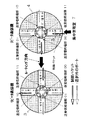
図2は本発明の一実施例によるリピータ通信機の集約方向のデータ転送を説明するための図であり、図3は本発明の一実施例によるリピータ通信機のルーティング方向のデータ転送を説明するための図である。これら図2及び図3において、リピータ通信機3,4は4つの物理ポートを有し、双方向通信が可能となっている。尚、図2及び図3に示したリピータ通信機3,4は全く同じものであり、便宜上、集約方向のデータ転送方向とルーティング方向のデータ転送方向とを説明するために2つの図に分けている。
【0027】
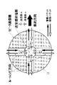
図4は本発明の一実施例によるリピータ通信機の設置後の個別アドレスの取得方法を説明するための図であり、図5は本発明の一実施例によるリピータ通信機の制御パケットのルーティング方法を説明するための図である。これら図4及び図5においては、集約方向における警報発呼を実行したリピータ通信機のアドレスの習得方法と、ルーティング方向における制御パケットを目標のリピータ通信機へ導く方法とを示している。
【0028】
これら図2〜図5を参照して本発明の一実施例によるリピータ通信機の動作について説明する。
【0029】
まず最初に、集約方向のデータ転送について図2を参照して説明する。リピータ通信機3は外部からの警報状態をOFF/ONで検知する。その後、リピータ通信機3の発呼機能によって警報状態を通知する警報パケット5を集約方向用のポート、つまりリピータ通信機3の送受信終端部11に設けられた送信器からポート番号“11”を介して送信する。
【0030】
続いて、次段のリピータ通信機4はそのリピータ機能によって1つまたは複数のリピータ通信機からポート番号“00”,“01”,“10”で受信した1つまたは複数の警報パケットを次のリピータ通信機へ、リピータ通信機4の送受信終端部11に設けられた送信器からポート番号“11”を介してリピート送信する。
【0031】
その際、リピータ通信機4は警報パケットを受信したポート番号を警報パケットに付加した上で次のリピータ通信機へリピート送信する。これらのリピータ通信機は警報パケットに対して常に1つの方向、つまり集約方向にのみ送信され、集中管理室へと転送され続ける。この結果、集中管理室では受信した警報パケットに付加された全てのリピータ通信機のポート番号列によって、どこで警報が発呼されたかを判断することができる。
【0032】
次に、ルーティング方向のデータ転送について図3を参照して説明する。目的のリピータ通信機までのポート番号列を持った制御パケット5はリピータ通信機4に送信される。このリピータ通信機4では受信した制御パケット5に付随しているポート番号列の先頭番号を見て、3つある出力ポートのいずれの番号に該当するのかを判断し、そのポートの方向、つまりルーティング方向にのみ送信される。
【0033】
この動作が次のリピータ通信機3でも繰り返され、最終的にポート番号列のない制御パケットを受信したリピータ通信機がその制御パケットを自分宛ての制御パケットであると判断し、集中管理室7からの制御命令にしたがって動作を行う。場合によっては、命令制御の実行完了を示すパケットを集中管理室7に送信しても良い。
【0034】
上記の図4及び図5を参照してリピータ通信機のアドレスの習得方法と、制御パケットを目標のリピータ通信機へ導く方法とについて説明する。図4にはリピータ通信機の設置後において、集中管理室7が個別アドレスを取得する方法を示している。例えば、リピータ通信機Gのアドレスはリピータ通信機Gから送信されたあるパケットが、中央管理室に到着する経路上の全てのリピータ通信機の受信ポート番号を連続させた数値である。つまり、リピータ通信機FのPort“00”,リピータ通信機CのPort“10”,リピータ通信機AのPort“01”で、“011000”となる。
【0035】
また同様に、リピータ通信機Eのアドレスはリピータ通信機CのPort“00”,リピータ通信機AのPort“01”で、“0100”になる。前二者のアドレスのように、経路長によってアドレス長が異なるため、パケットデータの先頭にはアドレス長を示すサイズデータをアドレスとともに併記する必要がある。
【0036】
図5にはルーティング方向における制御パケットを目標のリピータ通信機へ導く方法を示している。制御を実行させたい目的の制御機器が搭載されたリピータ通信機、例えばリピータ通信機Gに制御パケットを送信する場合には、まずリピータ通信機Aで集中管理室7から送信された制御パケットに付加されているアドレスデータ▲1▼“011000”の上位2ビットからリピート送信する送信ポート番号が“01”であることを判断し、その上位2ビットを削除後、新たなアドレスデータ▲2▼“1000”を持つパケットデータをリピータ通信機Cへ送信する。
【0037】
次に、リピータ通信機Cでは受信したアドレスデータ▲2▼“1000”の上位2ビットから送信ポート番号が“10”であることを判断し、その上位2ビットを削除後、新たなアドレスデータ▲3▼“00”を持つパケットデータをリピータ通信機Fへ送信する。
【0038】
続いて、リピータ通信機Fでは受信したアドレスデータ▲3▼“00”の上位2ビットから送出ポート番号が“00”であることを判断し、その上位2ビットを削除後、新たなアドレスデータ▲4▼“(ナシ)”を持つパケットデータをリピータ通信機Gへ送信する。
【0039】
ここで、各パケットデータの転送過程では、アドレス長を示すサイズデータも各リピータ通信機で書き変えられるため、データサイズを“0”で受け取るリピータ通信機Gはそれが自分宛ての制御パケットであることを判断することができる。
【0040】
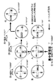
図6は本発明の一実施例によるビル内に設置されたリピータ通信機間の警報パケット転送の様子を示す図であり、図7は本発明の一実施例によるビル内に設置されたリピータ通信機間の制御パケット転送の様子を示す図であり、図8(a)〜(d)は本発明のパケットのフォーマットを示す図である。
【0041】
図9は本発明の一実施例によるリピータ通信機の内部構成を示すブロック図である。図9において、リピータ通信機は送信部1と、受信部2と、送信器TX00,TX01,TX10,TX11と、受信器RX00,RX01,RX10,RX11とから構成されている。
【0042】
送信部1はバッファ(buffer)11〜13と、スイッチ(SW)14と、フレーム終端部15と、フレーム生成部16とから構成されている。受信部2はバッファ(buffer)21と、フレーム終端部22と、フレーム生成部23、スイッチ(SW)24とから構成されている。
【0043】
これら図6〜図9を参照して本発明の一実施例による警報収集・機器制御用通信システムの動作について説明する。まず、ビル内に設置されたリピータ通信機間の警報パケット転送と制御パケット転送との様子を示す図6及び図7を基に、リピータ通信機の内部回路構成を示す図9を交えながら、本発明の一実施例によるリピータ通信機を用いたシステムの動作について説明する。
【0044】
図6に示すように、2階建てのビルに警報機を伴なったリピータ通信機の設置を完了した時点で、各リピータ通信機からの擬似発呼によって、図4の手法に習って、全てのリピータ通信機のアドレスデータを収集する。
【0045】
その中で、例えば2階のある部屋に設置された警報装置Pのアドレスデータは、リピータ通信機“P→Q→R→S→T→U→V”を経由することから、パケットのフォーマットは、「7e」,「a」,「b」,「c」,「d」,「e」,「7e」というような構成をなす。
【0046】
ここで、「7e」はフラグ(1バイト)である(“01111110”)。「a」はリピータ通信機1台のポート数(3ビット:最大8ポート)で、“000”が1ポート、“001”が2ポート、“010”が3ポート、“011”が4ポート、“100”が5ポート、“101”が6ポート、“110”が7ポート、“111”が8ポートをそれぞれ示している。
【0047】
「b」は通過する全リピータ通信機の数(13ビット:最大8192個)であり(“0000000001100”)、「c」は通過する全リピータ通信機のポート番号列であり(“010101011010”)、「d」は警報データ(1バイト)であり(“********”)、「e」はCRC(Cyclic Redundancy Check)である(“********”)。上記の図8(a)に示す構成の場合には4ポートで、ポート番号列cは2ビット単位の構成となる。
【0048】
上述したフレーム生成の過程は、図9に示すリピータ通信機の内部構成のうちの送信部1で決定される。送信部1では受信器RX00,RX01,RX10の3ポートから入力される受信データをそれぞれのバッファ11,12,13に蓄積し、受信タイミングの早い順番に「7e」のフラグで囲まれたパケットデータをフレーム終端部15で終端する。
【0049】
続いて、フレーム生成部16において、フレーム終端部15で終端したパケットデータに当該データパケットが入力されたポート番号“00”,“01”,“10”のいずれかを上記パケットフレーム構成[図8(a)]の「c」部の先頭に追加し、またアドレス長を示す「b」部とCRCを示す「e」部とが修正された後、送信器TX11へと出力される。
【0050】
以上の仕組みによって、全てのリピータ通信機を設置後に全てのアドレスを収集してあれば、警報装置Pの例のように、どこの部屋で警報が発生したかを容易に知ることができる。
【0051】
次に、制御を実行したい警報機のある部屋へ制御パケットを送信する場合、図5の手法に習って、ビルの中にある各リピータ通信機は集中管理室7からの制御パケットを転送する。例えば、集中制御室7から2階のある部屋にある警報装置Pに制御パケットを転送する場合、リピータ通信機“V→U→T→S→R→Q→P”を経由することから、パケットのフォーマットは最初、図8(b)に示すように、「7e」,「a」,「b」,「c」,「f」,「e」,「7e」という構成をなし、最終的に警報装置Pで、図8(c)に示すように、「7e」,「a」,「b」,「f」,「e」,「7e」という構成をなす。
【0052】
ここで、「f」は制御データ(1バイト)である(“********”)。上記の図8(b)及び図8(c)に示す構成の場合は4ポートで、ポート番号列cは2ビット単位の構成となる。
【0053】
上記の図8(c)に示す構成で明らかなように、最後に本パケットを受取る警報装置Pに併設されたリピータ通信機には、図8(a)に示す構成に設けられている通過する全リピータ通信機のポート番号列「c」がない。
【0054】
上述したフレーム生成の過程は、図9に示すリピータ通信機の内部構成のうちの受信部2で決定される。受信部2では受信器RX11のポートから入力される受信データをバッファ21に蓄積し、「7e」のフラグで囲まれたパケットデータをフレーム終端部22で終端し、通過する全リピータ通信機のポート番号列「c」部の先頭のポート番号を削除する。
【0055】
次に、フレーム生成部23において、ポート番号を一部削除したフレーム終端データを基に、アドレス長を示す「b」部とCRCを示す「e」部とが修正し直された後、削除したポート番号にしたがって送信器TX00,TX01,TX10のいずれかへと出力される。
【0056】
以上の仕組みによって、制御を実行したい警報機のある部屋へ制御パケットを容易に送信することができる。
【0057】
このように、リピータ通信機を警報収集及び機器制御のためのシステムに用いることによって、各リピータ通信機に個々のアドレスを事前に割り当てる手続きを実施することなく、集中管理室7で受信した警報データが何処のリピータ通信機から発呼された警報データかを容易に判断することができる。
【0058】
また、複数ある通信経路においてどのリピータ通信機へ送出すべき機器制御データかを、個々のリピータ通信機が容易に判断することができるルーティング機能を備えることができる。つまり、上記のリピータ通信機を用いることによって、リピータ通信機の設置工事前に個々のリピータ通信機へアドレスを与える必要が全くなく、また目的のリピータ通信機へ制御データ等を送出する際に、各リピータ通信機にルーティング方向を判断させるためのルーティングテーブルも必要なくなり、上述のような新しい通信方式によって、警報収集及び機器制御のための効率的なシステムを実現することができる。
【0059】
尚、本実施例ではビル内警報制御の通信方式に応用した場合の利便性を示すために使用例の一例について説明したが、使用例はこのような場合に限らず、大型プレス機や小型切削機等の工業用機器内の異常検出/制御、乗用車や航空機等の搬送機器内の異常検出/制御、そしてビニールハウス内の温度管理や家畜小屋の衛生管理等の酪農・農業面での利用等、上述した設置の容易性と構造の単純性とから、大量データの伝送要求が比較的少ないこのような広い分野でその効果を十分に期待することができる。
【0060】
図10は本発明の他の実施例によるビル内に設置された全てのリピータ通信機へのブロードキャストによる制御パケット転送の様子を示す図であり、図11は本発明の他の実施例によるリピータ通信機の内部構成を示すブロック図である。
【0061】
図11において、リピータ通信機は送信部8と、受信部2と、送信器TX000,TX001,……,TX110,TX111と、受信器RX000,RX001,……,RX110,RX111とから構成されている。
【0062】
送信部8はバッファ(buffer)81〜87と、スイッチ(SW)88と、フレーム終端部89と、フレーム生成部90とから構成されている。受信部2はバッファ(buffer)21と、フレーム終端部22と、フレーム生成部23、スイッチ(SW)24とから構成されている。
【0063】
図1では構成を簡潔にするために複数の集約方向用ポートを3つとしているが、図10で用いられているリピータ通信機は7方向からの警報データ等を受信する7つのポートにそれぞれ“000”,“001”,“010”,“011”,“100”,“101”,“110”のポート番号が設けられている。ここで、全部屋の全警報機に制御パケットをブロードキャスト送信する場合、基本的に図5に示す手法に習って、ビルの中にある各リピータ通信機は集中管理室7からのブロードキャスト制御パケットを転送する。
【0064】
この時、集中管理室7からのブロードキャスト制御パケットにある、通過する全リピータ通信機のポート番号列「c」部は”111”である。これは各リピータ通信機が受信した制御パケットがブロードキャスト制御パケットであり、全てのポートからリピート送信されなければならないことを示す。集中管理室7からのブロードキャスト制御パケットのフレームは、図8(d)に示すように、「7e」,「a」,「b」,「c」,「f」,「e」,「7e」という構成をなす。上記の図8(d)に示す構成の場合には8ポートで、ポート番号列「c」は3ビット単位の構成となる。
【0065】
上記の図8(d)に示す構成で明らかなように、ブロードキャスト制御パケットを受取る全ての警報装置に併設されたリピータ通信機には、図8(b)に示す構成に設けられ、通過する全リピータ通信機のポート番号列「c」が13ビット分すべて“0”となっている。
【0066】
上述のリピート送信に関わるフレーム生成の過程は、図11に示すリピータ通信機の内部構成のうちの受信部2で決定される。受信部2では受信器RX111のポートから入力される受信データをバッファ21に蓄積し、「7e」のフラグで囲まれたパケットデータをフレーム終端部22で終端し、通過する全リピータ通信機の数「b」部が全て“0”で、ポート番号列「c」部が“111”であることから、受信パケットがブロードキャストパケットであることを検出し、検出内容をPORT番号25によって、フレーム生成部23とスイッチ24とに伝える。
【0067】
次に、フレーム生成部23では受信パケットがブロードキャストパケットであることから、終端フレームをそのまま再度フレーム化し、スイッチ24で全ての送信器TX000,TX001,TX010,TX011,TX100,TX101,TX110へと出力される。以上の仕組みによって、制御を実行させる全ての警報機のある部屋へ制御パケットを容易に送信することができる。
【0068】
【発明の効果】
以上説明したように本発明によれば、複数の通信機と集中管理部とからなるネットワークにおいて、複数の通信機からの警報データを集中管理部に収集し、集中管理部からの制御データを所望の通信機に伝送する警報収集・機器制御用通信システムにおいて、ネットワーク上への通信機の設置時にその通信機から集中管理部への発呼を行い、集中管理部への発呼データを中継する際にその発呼データを受信したポート番号を当該発呼データのポート番号の累積列に追加することで、集中管理部が発呼データが通過した全ての通信機のポート番号を列として累積記憶し、それらの通信機による経路を示すポート番号の累積列を発呼を行った通信機のアドレスとして記憶管理することによって、通信端末の設置時にアドレスの設定を実施することなく、かつ各通信端末がアドレス管理のためのテーブルを持つことなく、警報データや制御データを効率良くルーティングすることができるという効果がある。
【図面の簡単な説明】
【図1】本発明の一実施例によるリピータ通信機の基本構成を示す図である。
【図2】本発明の一実施例によるリピータ通信機の集約方向のデータ転送を説明するための図である。
【図3】本発明の一実施例によるリピータ通信機のルーティング方向のデータ転送を説明するための図である。
【図4】本発明の一実施例によるリピータ通信機の設置後の個別アドレスの取得方法を説明するための図である。
【図5】本発明の一実施例によるリピータ通信機の制御パケットのルーティング方法を説明するための図である。
【図6】本発明の一実施例によるビル内に設置されたリピータ通信機間の警報パケット転送の様子を示す図である。
【図7】本発明の一実施例によるビル内に設置されたリピータ通信機間の制御パケット転送の様子を示す図である。
【図8】(a)〜(d)は本発明のパケットのフォーマットを示す図である。
【図9】本発明の一実施例によるリピータ通信機の内部構成を示すブロック図である。
【図10】本発明の他の実施例によるビル内に設置された全てのリピータ通信機へのブロードキャストによる制御パケット転送の様子を示す図である。
【図11】本発明の他の実施例によるリピータ通信機の内部構成を示すブロック図である。
【符号の説明】
1,8 送信部
2 受信部
3,4 リピータ通信機
7 集中管理室
11〜13,81〜87,21 バッファ
14,24,88 スイッチ
15,22,89 フレーム終端部
16,23,90 フレーム生成部
TX00,TX01,TX10,TX11,TX000,TX001,……,TX110,TX111 送信器
RX00,RX01,RX10,RX11,RX000,RX001,……,RX110,RX111 受信器[0001]
BACKGROUND OF THE INVENTION
The present invention relates to a communication system and method for alarm collection / device control, and more particularly to a communication method used for alarm collection and device control.
[0002]
[Prior art]
Conventionally, communication systems used for alarm collection and device control are generally built in buildings and factories by LAN (Local Area Network) typified by Ethernet, token ring, and the like. However, in recent years, as the demand for such LAN construction increases, cases of newly laying LANs in old buildings and existing houses are increasing.
[0003]
In addition, the above general LAN, which requires a relatively large capital investment, does not require data transfer as fast as the LAN, and monitors small-capacity data such as alarm data and control data in a centralized management room. There is a demand for the construction of inexpensive communication equipment that can be controlled.
[0004]
In order to respond to this request, for example, a method is provided in which a communication terminal connected to the communication system is provided with a unique address in advance, and a reply is returned as a report of the state of the terminal device only for the target address from the parent device Has been proposed. This technique is disclosed in Japanese Patent Laid-Open No. 04-275798 (first publication).
[0005]
There is also a method in which branches on a network are divided into network use networks using a device called a branch repeater. This method is disclosed in Japanese Patent Application Laid-Open No. 58-081360 (second publication).
[0006]
[Problems to be solved by the invention]
When using the method disclosed in the first publication, the conventional communication system described above has an initial setting procedure for assigning a unique address to each communication terminal from the stage of system installation. For this reason, when the number of communication terminals increases or decreases during operation, it is necessary to provide address management information to both the communication terminal and the parent apparatus in order to perform address assignment.
[0007]
As a result, there is a problem that installation work for communication terminals requires setting the addresses for the required number for each communication terminal, which requires a lot of time and labor.
[0008]
In addition, when the technique disclosed in the second publication is used, each branch repeater has a branch repeater because the branch repeater is used to identify which branch the data transmitted through the network is necessary for. A table is required to remember the destination address that matches or does not match each time.
[0009]
Therefore, if there are inevitably many branches and the number of communication terminals on each branch is large, the number of tables becomes large, and there is a problem of inviting an increase in memory capacity when building with hardware. In other words, the above method is an effective means when assuming relatively large capital investment such as Ethernet or token link, but small-capacity data such as alarm data and control data is monitored in the centralized management room. It can be said that it is not suitable for the construction of inexpensive communication equipment that can be controlled.
[0010]
Therefore, the object of the present invention is to solve the above-mentioned problems, without setting addresses when installing communication terminals, and without having a table for address management in each communication terminal, alarm data and control data. It is an object of the present invention to provide a communication system for alarm collection / device control and a method thereof.
[0011]
[Means for Solving the Problems]
The alarm collection / device control communication system according to the present invention collects alarm data from the plurality of communication devices in the central management unit in a network including a plurality of communication devices and a central management unit. A communication system for alarm collection / device control that transmits control data to a desired communication device,
Means for making a call to the centralized management unit when installed on the network, and a port number of the call data when receiving the call data when relaying the call data to the centralized management unit Each of the plurality of communication devices comprises means for adding to a cumulative row of numbers,
The centralized management unit accumulates and stores as a column the port numbers of all the communication devices through which the call data has passed, and the accumulated column of port numbers indicating the paths by those communication devices is the address of the communication device that made the call As memory management,
The data transmitted from each of the plurality of communication devices has a data format surrounded by a flag, and the number of ports of one communication device and the number of all communication devices that pass through and the number of all communication devices that pass through A port number sequence, one of the control data and one of the alarm data, and a CRC (Cyclic Redundancy Check) are sequentially arranged and configured.
The data length of each port number is a length corresponding to the number of ports..
[0012]
The communication method for alarm collection / device control according to the present invention collects alarm data from the plurality of communication devices in the centralized management unit in a network composed of a plurality of communication devices and a centralized management unit. Is a communication method for alarm collection and device control that transmits control data to a desired communication device, and when the communication device is installed on the network, makes a call from the communication device to the centralized management unit, and When relaying the call data to the centralized management unit, the centralized management unit adds the port number that received the call data to the accumulated column of the port numbers of the call data, so that the centralized management unit passes the call data. And cumulatively store the port numbers of all the communication devices as a column, and store and manage the cumulative column of port numbers indicating the route by those communication devices as the address of the communication device that made the call,The data transmitted from each of the plurality of communication devices has a data format surrounded by a flag, and the number of ports of one communication device and the number of all communication devices that pass through and the number of all communication devices that pass through A port number string, one of the control data and one of the alarm data, and CRC (Cyclic Redundancy Check) are sequentially arranged, and the data length of each port number is a length corresponding to the number of ports..
[0013]
That is, the alarm collection / device control communication system according to the present invention receives alarm data from a remote repeater communication device via a repeater communication device that also serves as an alarm call or device control function, or receives a remote repeater communication device. In a communication system centered on a centralized control room that transmits device control data to a communication device, an alarm from any repeater communication device can be used without performing a procedure to assign individual addresses to each repeater communication device in advance. It is characterized by having a routing function that allows each individual repeater communication device to easily determine whether it is data or device control data to be transmitted to which repeater communication device.
[0014]
More specifically, the repeater communication device according to the present invention is roughly divided into two data transfer directions. One of the data transfer directions is an aggregation direction, which is the direction of data for aggregating alarm data from multi-directional repeater communication devices toward the central control room, and the other of the data transfer directions is a routing direction for centralized management. This is the direction of data for sending control data or the like from a single direction for a room to a plurality of repeater communication devices.
[0015]
When there are three ports in the above-mentioned multi-direction, the repeater communication device assigns port numbers “00”, “01”, and “10” to the three ports that receive alarm data from three directions, respectively. .
[0016]
The port number functions differently in the aggregation direction and the routing direction. First, in the aggregation direction, the input port number of the repeater communication device next to the first repeater communication device that calls out alarm data etc. is stored first, and the input port number of the repeater communication device that is routed one after another is stored in the final direction. Sent to the central control room.
[0017]
As a result, it is possible to determine where an alarm or the like has occurred by pre-corresponding the location of the first repeater communication device with the stored port number sequence.
[0018]
Next, if you want to send control data etc. to the desired repeater communicator in the routing direction, the next repeater communicator receives the centralized control room that you received by sending a list of port numbers that indicate the location you collected in advance. From which of the three ports should be output.
[0019]
When the output port can be determined, the head port number of the received data used to determine the output port is deleted and sent to the next repeater communication device. By repeating this, the repeater communicator that has received the control data whose port number is no longer arranged finally executes its control.
[0020]
Therefore, by using the repeater communication device of the present invention, there is no need to give an address to each repeater communication device in advance, and when sending control data or the like to the target repeater communication device, A table for determining the routing direction is not necessary, and an efficient system for alarm collection and device control can be realized.
[0021]
DETAILED DESCRIPTION OF THE INVENTION
Next, an embodiment of the present invention will be described with reference to the drawings. FIG. 1 is a diagram showing a basic configuration of a repeater communication device according to an embodiment of the present invention. In FIG. 1, the
[0022]
The other of the data transfer directions is a routing direction, which is a direction of data for sending control data or the like from a single direction for the centralized management room to a plurality of repeater communication devices. In FIG. 1, three ports in a plurality of directions are used in order to simplify the configuration. Here, in the
[0023]
The port number functions differently in the aggregation direction and the routing direction. First, in the aggregation direction, the input port number of the repeater communication device next to the first repeater communication device that calls out alarm data etc. is stored first, and the input port number of the repeater communication device that is routed one after another is stored in the final direction. Sent to the central control room. As a result, it is possible to determine where an alarm or the like has occurred by associating the location of the first repeater communication device with the stored port number in advance.
[0024]
Next, if you want to send control data etc. to the desired repeater communicator in the routing direction, the next repeater communicator receives the centralized control room that you received by sending out a list of port numbers that indicate the location you collected in advance. From which of the three ports should be output. When the output port can be determined, the head port number of the received data used to determine the output port is deleted and sent to the next repeater communication device. By repeating this process, the repeater communication device that has finally received control data with no port number sequence executes the control data.
[0025]
Therefore, by using the
[0026]
FIG. 2 is a diagram for explaining data transfer in the aggregation direction of the repeater communication device according to an embodiment of the present invention. FIG. 3 is a diagram for explaining data transfer in the routing direction of the repeater communication device according to the embodiment of the present invention. FIG. 2 and 3, the
[0027]
FIG. 4 is a diagram for explaining a method for obtaining an individual address after installation of a repeater communication device according to an embodiment of the present invention, and FIG. 5 is a control packet routing method for a repeater communication device according to an embodiment of the present invention. It is a figure for demonstrating. 4 and 5 show a method of acquiring an address of a repeater communication device that has executed an alarm call in the aggregation direction, and a method of guiding a control packet in the routing direction to a target repeater communication device.
[0028]
The operation of the repeater communication device according to the embodiment of the present invention will be described with reference to FIGS.
[0029]
First, data transfer in the aggregation direction will be described with reference to FIG. The
[0030]
Subsequently, the
[0031]
At that time, the
[0032]
Next, data transfer in the routing direction will be described with reference to FIG. A control packet 5 having a port number string up to the target repeater communication device is transmitted to the
[0033]
This operation is repeated in the next
[0034]
The method for acquiring the address of the repeater communication device and the method for guiding the control packet to the target repeater communication device will be described with reference to FIGS. FIG. 4 shows a method in which the
[0035]
Similarly, the address of the repeater communication device E is Port “00” of the repeater communication device C, Port “01” of the repeater communication device A, and becomes “0100”. Since the address length differs depending on the path length like the former two addresses, it is necessary to write size data indicating the address length together with the address at the head of the packet data.
[0036]
FIG. 5 shows a method of guiding a control packet in the routing direction to a target repeater communication device. When a control packet is transmitted to a repeater communication device equipped with a target control device for which control is to be executed, for example, the repeater communication device G, the control packet is first added to the control packet transmitted from the
[0037]
Next, the repeater communication device C determines that the transmission port number is “10” from the upper 2 bits of the received address data (2) “1000”, deletes the upper 2 bits, and then creates new address data 3) Packet data having “00” is transmitted to the repeater communication device F.
[0038]
Subsequently, the repeater communication device F determines that the transmission port number is “00” from the upper 2 bits of the received address data (3) “00”, deletes the upper 2 bits, and then creates new address data 4) Transmit the packet data having “(no)” to the repeater communication device G.
[0039]
Here, in the transfer process of each packet data, since the size data indicating the address length can be rewritten by each repeater communication device, the repeater communication device G that receives the data size of “0” is the control packet addressed to itself. Can be judged.
[0040]
FIG. 6 is a diagram showing a state of alarm packet transfer between repeater communication devices installed in a building according to an embodiment of the present invention. FIG. 7 is a diagram showing repeater communication installed in a building according to an embodiment of the present invention. It is a figure which shows the mode of the control packet transfer between machines, and Fig.8 (a)-(d) is a figure which shows the format of the packet of this invention.
[0041]
FIG. 9 is a block diagram showing an internal configuration of a repeater communication device according to an embodiment of the present invention. In FIG. 9, the repeater communicator includes a transmission unit 1, a reception unit 2, transmitters TX00, TX01, TX10, and TX11, and receivers RX00, RX01, RX10, and RX11.
[0042]
The transmission unit 1 includes
[0043]
The operation of the alarm collection / device control communication system according to an embodiment of the present invention will be described with reference to FIGS. First, based on FIG. 6 and FIG. 7 showing the state of alarm packet transfer and control packet transfer between repeater communication devices installed in a building, this FIG. 9 showing the internal circuit configuration of the repeater communication device is used. An operation of a system using a repeater communication device according to an embodiment of the invention will be described.
[0044]
As shown in FIG. 6, when the installation of the repeater communication device with the alarm device in the two-story building is completed, all of the techniques shown in FIG. Collect the address data of the repeater communicator.
[0045]
Among them, for example, the address data of the alarm device P installed in a room on the second floor passes through the repeater communication device “P → Q → R → S → T → U → V”, so the packet format is , “7e”, “a”, “b”, “c”, “d”, “e”, “7e”.
[0046]
Here, “7e” is a flag (1 byte) (“01111110”). “A” is the number of ports of one repeater communication device (3 bits: maximum 8 ports), “000” is 1 port, “001” is 2 ports, “010” is 3 ports, “011” is 4 ports, “100” indicates 5 ports, “101” indicates 6 ports, “110” indicates 7 ports, and “111” indicates 8 ports.
[0047]
“B” is the number of all repeater communication devices that pass through (13 bits: maximum 8192) (“0000000001100”), “c” is the port number string of all the repeater communication devices that pass (“0101010111010”), “D” is alarm data (1 byte) (“*******”), and “e” is a CRC (Cyclic Redundancy Check) (“*********”). In the case of the configuration shown in FIG. 8A, there are 4 ports and the port number string c has a 2-bit unit configuration.
[0048]
The above-described frame generation process is determined by the transmission unit 1 in the internal configuration of the repeater communication device shown in FIG. The transmission unit 1 accumulates reception data input from the three ports RX00, RX01, RX10 in the
[0049]
Subsequently, in the
[0050]
With the above mechanism, as long as all addresses are collected after all repeater communicators are installed, it is possible to easily know in which room the alarm has occurred as in the example of the alarm device P.
[0051]
Next, when transmitting a control packet to a room with an alarm device for which control is to be executed, each repeater communicator in the building transfers a control packet from the
[0052]
Here, “f” is control data (1 byte) (“*******”). In the case of the configuration shown in FIGS. 8B and 8C, there are 4 ports, and the port number string c has a 2-bit unit configuration.
[0053]
As is clear from the configuration shown in FIG. 8C, the repeater communication device provided in the alarm device P that finally receives the packet passes through the repeater communication device provided in the configuration shown in FIG. There is no port number string “c” for all repeater communication devices.
[0054]
The frame generation process described above is determined by the receiving unit 2 in the internal configuration of the repeater communication device shown in FIG. The reception unit 2 accumulates reception data input from the port of the receiver RX11 in the
[0055]
Next, the
[0056]
With the above mechanism, it is possible to easily transmit a control packet to a room with an alarm device to be controlled.
[0057]
As described above, by using the repeater communication device in the system for alarm collection and device control, the alarm data received by the
[0058]
In addition, it is possible to provide a routing function that allows individual repeater communication devices to easily determine which repeater communication device should be sent to which repeater communication data in a plurality of communication paths. In other words, by using the above repeater communicator, there is no need to give an address to each repeater communicator before installation work of the repeater communicator, and when sending control data to the target repeater communicator, A routing table for causing each repeater communicator to determine the routing direction is not necessary, and an efficient system for alarm collection and device control can be realized by the new communication method as described above.
[0059]
In this embodiment, an example of a usage example has been described in order to show convenience when applied to a communication method for alarm control in a building. However, the usage example is not limited to such a case, and a large press or small cutting machine is used. Anomaly detection / control in industrial equipment such as machines, anomaly detection / control in transport equipment such as passenger cars and airplanes, and dairy / agriculture usage such as temperature management in greenhouses and hygiene management of livestock sheds, etc. Due to the ease of installation and the simplicity of the structure described above, the effect can be sufficiently expected in such a wide field where there are relatively few requests for transmission of a large amount of data.
[0060]
FIG. 10 is a diagram showing how control packets are transferred by broadcast to all repeater communication devices installed in a building according to another embodiment of the present invention, and FIG. 11 is a repeater communication according to another embodiment of the present invention. It is a block diagram which shows the internal structure of a machine.
[0061]
In FIG. 11, the repeater communicator includes a transmission unit 8, a reception unit 2, transmitters TX000, TX001,..., TX110, TX111, and receivers RX000, RX001,. .
[0062]
The transmission unit 8 includes buffers 81 to 87, a switch (SW) 88, a
[0063]
In FIG. 1, a plurality of aggregation direction ports are set to three in order to simplify the configuration. However, the repeater communication device used in FIG. 10 has seven ports that receive alarm data and the like from seven directions. Port numbers of “000”, “001”, “010”, “011”, “100”, “101”, “110” are provided. Here, when a control packet is broadcast to all alarm devices in all rooms, each repeater communication device in the building basically transmits a broadcast control packet from the
[0064]
At this time, the port number string “c” part of all the repeater communication devices in the broadcast control packet from the
[0065]
As is clear from the configuration shown in FIG. 8 (d) above, the repeater communication devices provided in all alarm devices that receive broadcast control packets are provided in the configuration shown in FIG. The port number string “c” of the repeater communication device is “0” for all 13 bits.
[0066]
The frame generation process related to the above repeat transmission is determined by the receiving unit 2 in the internal configuration of the repeater communication device shown in FIG. The reception unit 2 accumulates the reception data input from the port of the
[0067]
Next, since the received packet is a broadcast packet in the
[0068]
【The invention's effect】
As described above, according to the present invention, in a network composed of a plurality of communication devices and a centralized management unit, alarm data from a plurality of communication devices is collected in the centralized management unit, and control data from the centralized management unit is desired. In the communication system for alarm collection and device control that is transmitted to other communication devices, when the communication device is installed on the network, the communication device makes a call to the central management unit and relays the call data to the central management unit When the port number that received the call data is added to the accumulated column of port numbers of the call data, the centralized management unit accumulates the port numbers of all the communication devices that have passed the call data as a column. The address is set when the communication terminal is installed by storing and managing the accumulated column of port numbers indicating the route by the communication device as the address of the communication device that made the call. Ku, and without each communication terminal has a table for address management, there is an effect that alarm data and control data can be efficiently routed.
[Brief description of the drawings]
FIG. 1 is a diagram showing a basic configuration of a repeater communication device according to an embodiment of the present invention.
FIG. 2 is a diagram for explaining data transfer in the aggregation direction of a repeater communication device according to an embodiment of the present invention;
FIG. 3 is a diagram for explaining data transfer in a routing direction of a repeater communication device according to an embodiment of the present invention;
FIG. 4 is a diagram for explaining a method for obtaining an individual address after installation of a repeater communication device according to an embodiment of the present invention.
FIG. 5 is a diagram for explaining a control packet routing method of a repeater communication device according to an embodiment of the present invention;
FIG. 6 is a diagram showing how alarm packets are transferred between repeater communication devices installed in a building according to an embodiment of the present invention.
FIG. 7 is a diagram showing how control packets are transferred between repeater communication devices installed in a building according to an embodiment of the present invention.
FIGS. 8A to 8D are diagrams showing packet formats of the present invention.
FIG. 9 is a block diagram showing an internal configuration of a repeater communication device according to an embodiment of the present invention.
FIG. 10 is a diagram showing how control packets are transferred by broadcast to all repeater communication devices installed in a building according to another embodiment of the present invention.
FIG. 11 is a block diagram showing an internal configuration of a repeater communication device according to another embodiment of the present invention.
[Explanation of symbols]
1,8 Transmitter
2 receiver
3,4 repeater communication device
7 Central management room
11-13, 81-87, 21 buffer
14, 24, 88 switches
15, 22, 89 Frame termination
16, 23, 90 frame generator
TX00, TX01, TX10, TX11, TX000, TX001, ..., TX110, TX111 Transmitter
RX00, RX01, RX10, RX11, RX000, RX001, ..., RX110, RX111 Receiver
Claims (8)
前記ネットワーク上への設置時に前記集中管理部への発呼を行う手段と、前記集中管理部への発呼データを中継する際にその発呼データを受信したポート番号を当該発呼データのポート番号の累積列に追加する手段とを前記複数の通信機各々に有し、
前記集中管理部は前記発呼データが通過した全ての通信機のポート番号を列として累積記憶し、それらの通信機による経路を示すポート番号の累積列を前記発呼を行った通信機のアドレスとして記憶管理するようにし、
前記複数の通信機各々から発呼されるデータは、フラグに囲まれたデータフォーマットを持ち、先頭に通信機1台のポート数と通過する全ての通信機の数と通過する全ての通信機のポート番号列と前記制御データ及び前記警報データの一方とCRC(Cyclic Redundancy Check)とを順次整列して構成するようにし、
前記ポート番号各々のデータ長は前記ポート数に応じた長さであることを特徴とする警報収集・機器制御用通信システム。In a network consisting of a plurality of communication devices and a centralized management unit, alarm data collected from the plurality of communication devices is collected in the centralized management unit, and control data from the centralized management unit is transmitted to a desired communication device A communication system for device control,
Means for making a call to the centralized management unit when installed on the network, and a port number of the call data when receiving the call data when relaying the call data to the centralized management unit Means for adding to the cumulative column of numbers in each of the plurality of communication devices,
The centralized management unit accumulates and stores as a column the port numbers of all the communication devices through which the call data has passed, and the accumulated column of port numbers indicating the paths by those communication devices is the address of the communication device that made the call As memory management and
The data transmitted from each of the plurality of communication devices has a data format surrounded by a flag, and the number of ports of one communication device and the number of all communication devices that pass through and the number of all communication devices that pass through A port number sequence, one of the control data and one of the alarm data, and a CRC (Cyclic Redundancy Check) are sequentially arranged and configured.
A communication system for alarm collection / device control, wherein the data length of each port number is a length corresponding to the number of ports .
前記複数の通信機各々から発呼されるデータは、フラグに囲まれたデータフォーマットを持ち、先頭に通信機1台のポート数と通過する全ての通信機の数と通過する全ての通信機のポート番号列と前記制御データ及び前記警報データの一方とCRC(Cyclic Redundancy Check)とを順次整列して構成するようにし、The data transmitted from each of the plurality of communication devices has a data format surrounded by a flag, and the number of ports of one communication device and the number of all communication devices that pass through and the number of all communication devices that pass through A port number sequence, one of the control data and one of the alarm data, and a CRC (Cyclic Redundancy Check) are sequentially arranged and configured.
前記ポート番号各々のデータ長は前記ポート数に応じた長さであることを特徴とする警報収集・機器制御用通信方法。The communication method for alarm collection / device control, wherein the data length of each port number is a length corresponding to the number of ports.
Priority Applications (1)
| Application Number | Priority Date | Filing Date | Title |
|---|---|---|---|
| JP2000203006A JP3662819B2 (en) | 2000-07-05 | 2000-07-05 | Alarm collection / device control communication system and method |
Applications Claiming Priority (1)
| Application Number | Priority Date | Filing Date | Title |
|---|---|---|---|
| JP2000203006A JP3662819B2 (en) | 2000-07-05 | 2000-07-05 | Alarm collection / device control communication system and method |
Publications (2)
| Publication Number | Publication Date |
|---|---|
| JP2002026920A JP2002026920A (en) | 2002-01-25 |
| JP3662819B2 true JP3662819B2 (en) | 2005-06-22 |
Family
ID=18700458
Family Applications (1)
| Application Number | Title | Priority Date | Filing Date |
|---|---|---|---|
| JP2000203006A Expired - Fee Related JP3662819B2 (en) | 2000-07-05 | 2000-07-05 | Alarm collection / device control communication system and method |
Country Status (1)
| Country | Link |
|---|---|
| JP (1) | JP3662819B2 (en) |
Families Citing this family (2)
| Publication number | Priority date | Publication date | Assignee | Title |
|---|---|---|---|---|
| JP4780724B2 (en) * | 2007-05-07 | 2011-09-28 | Necアクセステクニカ株式会社 | Repeater communication device, centralized management terminal and communication system |
| KR100795316B1 (en) * | 2007-05-09 | 2008-01-21 | 금샘나라(주) | Preparing method for functional fermented liquor using sap |
-
2000
- 2000-07-05 JP JP2000203006A patent/JP3662819B2/en not_active Expired - Fee Related
Also Published As
| Publication number | Publication date |
|---|---|
| JP2002026920A (en) | 2002-01-25 |
Similar Documents
| Publication | Publication Date | Title |
|---|---|---|
| US5852405A (en) | Wireless LAN system | |
| JP4765973B2 (en) | Communication route construction method and communication terminal | |
| US20070086362A1 (en) | Network management method and communications network system | |
| EP0936779B1 (en) | Network system | |
| US8509238B2 (en) | Communication network, information processor and address assigning method | |
| KR100836818B1 (en) | Multi-type Air Conditioner Group Supervisory Controlling Method | |
| JP3662819B2 (en) | Alarm collection / device control communication system and method | |
| JPWO2007029337A1 (en) | Ad hoc network equipment that reduces data loss | |
| JPH0936916A (en) | Packet repeating system for radio transmission | |
| JPH11341041A (en) | Relay communication system, its data transfer guarantee monitoring method and communication equipment used for the method | |
| JP2001298466A (en) | Interface link layer device and network setting method | |
| JP6757976B2 (en) | Base stations, control systems, and base station control methods | |
| JP4573459B2 (en) | Wireless terminal device, transmission control device, wireless transmission control method, and program | |
| JPH11215186A (en) | Network system | |
| JP2002305776A (en) | Telemeter system | |
| JP7475387B2 (en) | Wireless Mesh Network System | |
| JP7215483B2 (en) | Communication systems and monitoring equipment | |
| CN113347684B (en) | Internet of things communication method and equipment with multi-stage relay networking capability | |
| JP6957142B2 (en) | Control device, wireless communication device and channel control method | |
| JP2008079116A (en) | Method of setting monitor control line | |
| JP3116217B2 (en) | Network system | |
| CN100375438C (en) | Dynamic route collocating method for network management device based on E1 communication | |
| JPH11187453A (en) | Apparatus and system for data communication | |
| JP3159129B2 (en) | Network monitoring method | |
| JP2001156849A (en) | Communication network system, radio communication terminal, and communication control method |
Legal Events
| Date | Code | Title | Description |
|---|---|---|---|
| RD01 | Notification of change of attorney |
Free format text: JAPANESE INTERMEDIATE CODE: A7421 Effective date: 20050314 |
|
| A61 | First payment of annual fees (during grant procedure) |
Free format text: JAPANESE INTERMEDIATE CODE: A61 Effective date: 20050324 |
|
| R150 | Certificate of patent or registration of utility model |
Free format text: JAPANESE INTERMEDIATE CODE: R150 |
|
| FPAY | Renewal fee payment (event date is renewal date of database) |
Free format text: PAYMENT UNTIL: 20080401 Year of fee payment: 3 |
|
| FPAY | Renewal fee payment (event date is renewal date of database) |
Free format text: PAYMENT UNTIL: 20090401 Year of fee payment: 4 |
|
| FPAY | Renewal fee payment (event date is renewal date of database) |
Free format text: PAYMENT UNTIL: 20100401 Year of fee payment: 5 |
|
| FPAY | Renewal fee payment (event date is renewal date of database) |
Free format text: PAYMENT UNTIL: 20110401 Year of fee payment: 6 |
|
| FPAY | Renewal fee payment (event date is renewal date of database) |
Free format text: PAYMENT UNTIL: 20120401 Year of fee payment: 7 |
|
| FPAY | Renewal fee payment (event date is renewal date of database) |
Free format text: PAYMENT UNTIL: 20120401 Year of fee payment: 7 |
|
| FPAY | Renewal fee payment (event date is renewal date of database) |
Free format text: PAYMENT UNTIL: 20130401 Year of fee payment: 8 |
|
| FPAY | Renewal fee payment (event date is renewal date of database) |
Free format text: PAYMENT UNTIL: 20130401 Year of fee payment: 8 |
|
| FPAY | Renewal fee payment (event date is renewal date of database) |
Free format text: PAYMENT UNTIL: 20140401 Year of fee payment: 9 |
|
| S111 | Request for change of ownership or part of ownership |
Free format text: JAPANESE INTERMEDIATE CODE: R313111 |
|
| R350 | Written notification of registration of transfer |
Free format text: JAPANESE INTERMEDIATE CODE: R350 |
|
| LAPS | Cancellation because of no payment of annual fees |