JP3662481B2 - Panel-shaped material fixture and mounting structure - Google Patents
Panel-shaped material fixture and mounting structure Download PDFInfo
- Publication number
- JP3662481B2 JP3662481B2 JP2000221611A JP2000221611A JP3662481B2 JP 3662481 B2 JP3662481 B2 JP 3662481B2 JP 2000221611 A JP2000221611 A JP 2000221611A JP 2000221611 A JP2000221611 A JP 2000221611A JP 3662481 B2 JP3662481 B2 JP 3662481B2
- Authority
- JP
- Japan
- Prior art keywords
- panel
- rising
- groove
- fixture
- engagement
- Prior art date
- Legal status (The legal status is an assumption and is not a legal conclusion. Google has not performed a legal analysis and makes no representation as to the accuracy of the status listed.)
- Expired - Lifetime
Links
Images


Description
【0001】
【発明の属する技術分野】
本発明は、家屋等の建物の幕板、外装材、外装化粧板材、内壁材等のパネル状材を下地材等の支持材に取り付けるためのパネル状材の取付具および取付構造に関する。
【0002】
【従来の技術】
従来、前記のようなパネル状材を下地材等の鉛直方向に立ち上がる支持材に取り付ける取付構造としては、前記支持材に釘、ねじ等により取付具を取り付けた後、さらにこの取付具にパネル状材を取り付けることにより、前記取付具を介して前記下地材にパネル状材を取り付ける取付構造がよく用いられている。
【0003】
【発明が解決しようとする課題】
しかしながら、前記従来のパネル状材の取付構造においては、パネル状材の取り付けが面倒であったり、支持材に対するパネル状材の取付強度が十分でないという問題があった。
【0004】
本発明は、このような従来の事情に鑑みてなされたもので、本発明の1つの目的は、家屋等の建物の幕板、外装材、外装化粧板材、内壁材等のパネル状材の取り付けを簡単迅速に行うことができるパネル状材の取付具および取付構造を提供することにある。
【0005】
本発明の他の目的は、支持材に対するパネル状材の取付強度を大きくすることができるパネル状材の取付具および取付構造を提供することにある。
【0006】
本発明の他の目的は、支持材に対するパネル状材のガタ止め、緩み止めを図ることができるパネル状材の取付具および取付構造を提供することにある。
【0007】
本発明のさらに他の目的は、以下の説明から明らかになろう。
【0008】
【課題を解決するための手段】
本発明によるパネル状材の取付具は、パネル状材を支持材に取り付けるためのパネル状材の取付具において、前記パネル状材は裏面側にそれぞれ横方向に延びる2本の溝部を設けられており、上側の前記溝部の下側の側壁面および下側の前記溝部の上側の側壁面が該パネル状材の大略厚さ方向に広がっているものであって、
前記支持材に取り付けられる取付具本体部と、比較的に弾性に富む金属板を加工してなる弾性係合部とを有してなり、
前記弾性係合部は、大略パネル状材と平行に広がることとなるようにして前記取付具本体部に取り付けられた基部と、この基部の上端から前記パネル状材の厚さ方向に立ち上が る上側立ち上がり部と、前記基部の下端から前記パネル状材の厚さ方向に立ち上がる下側立ち上がり部と、前記立ち上がり部の一部を、前記支持材から遠い側が切り残されるようにして他方の前記立ち上がり部側に切り起こしてなる弾性を有する係合片と、前記上側および下側立ち上がり部の先端からそれぞれ他方の前記立ち上がり部と反対側に湾曲された湾曲部とを有し、前記弾性係合部のうちの前記基部および前記立ち上がり部で構成される部分は横断面コの字状をなし、前記係合片は切り起こし方向に凹となるように湾曲されており、
前記上側および下側立ち上がり部が前記2本の溝部にそれぞれ侵入し、前記上側および下側立ち上がり部が前記パネル状材の前記2本の溝部間の部分を挟むこととなるようにして前記パネル状材が前記支持材側に押し込まれると、前記係合片が前記パネル状材に押されて弾性変形し、前記係合片の先端部が前記溝部の前記側壁面に押圧されることを特徴とするものである。
【0009】
本発明によるパネル状材の取付構造は、取付具を介してパネル状材を支持材に取り付けるパネル状材の取付構造において、
前記パネル状材は裏面側にそれぞれ横方向に延びる2本の溝部を設けられていて、上側の前記溝部の下側の側壁面および下側の前記溝部の上側の側壁面が該パネル状材の大略厚さ方向に広がっており、
前記取付具は、前記支持材に取り付けられる取付具本体部と、比較的に弾性に富む金属板を加工してなる弾性係合部とを有してなり、
前記弾性係合部は、大略パネル状材と平行に広がることとなるようにして前記取付具本体部に取り付けられた基部と、この基部の上端から前記パネル状材の厚さ方向に立ち上がる上側立ち上がり部と、前記基部の下端から前記パネル状材の厚さ方向に立ち上がる下側立ち上がり部と、前記立ち上がり部の一部を、前記支持材から遠い側が切り残されるようにして他方の前記立ち上がり部側に切り起こしてなる弾性を有する係合片と、前記上側および下側立ち上がり部の先端からそれぞれ他方の前記立ち上がり部と反対側に湾曲された湾曲部とを有し、前記弾性係合部のうちの前記基部および前記立ち上がり部で構成される部分は横断面コの字状をなし、前記係合片は切り起こし方向に凹となるように湾曲されており、
前記上側および下側立ち上がり部が前記2本の溝部にそれぞれ侵入し、前記上側および下側立ち上がり部が前記パネル状材の前記2本の溝部間の部分を挟むこととなるようにして前記パネル状材が前記支持材側に押し込まれることにより、前記係合片が前記パネル状材に押されて弾性変形し、前記係合片の先端部が前記溝部の前記側壁面に押圧されていることを特徴とするものである。
【0010】
本発明においては、まず取付具を支持材に取り付ける。次に、適当な位置関係に合わした状態で、パネル状材を支持材側に押し込んで行く。すると、係合片がパネル状材に押されて弾性変形し、係合片の先端部がパネル状材の大略厚さ方向に広がる各溝部の側壁面に押圧される。ここにおいて、係合片は支持材から遠い側から近い側へ突出するとともに、パネル状材の前記所定の面に対し凹となるように湾曲されているので、パネル状材が支持材から離れる方向に移動されようとすると、係合片の先端部が各溝部の側壁面に一層食い込もうとするので、パネル状材は支持材から離れる方向に移動できない。したがって、パネル状材が取付具を介して支持材に強固に確実に取り付けられる。
【0011】
また、このパネル状材の取付構造においては、パネル状材を支持材側に押し込んで行くだけでパネル状材を支持材に取り付けることができるので、パネル状材の取付作業を簡単迅速に行うことができる。
【0012】
さらに、係合片がパネル状材に弾性的に押圧されるので、支持材に対するパネル状材のガタ止め、緩み止めを図ることができる。
【0013】
【発明の実施の形態】
以下、本発明を図面に示す実施例に基づいて説明する。
【0014】
【実施例】
図1〜11は本発明の第一実施例を示し、このうち図1〜9は本実施例における取付具1、図10および11は本実施例におけるパネル状材2の取付構造を示している。なお、本実施例におけるパネル状材2は、例えば一戸建ての家屋の外壁部において1階と2階との間や2階と3階との間の境界部等に設けられる幕板である。
【0015】
取付具1は、それぞれ元々は別々の部材からなる取付具本体部3と弾性係合部4とをスポット溶接により互いに結合してなる。前記取付具本体部3は、比較的に厚いステンレス鋼板または鋼板等の比較的に強度が大きい金属板をプレス加工により成形してなり、矩形状の平面状部5とこの平面状部5の上端に連続して形成されたパネル状材受け部6とを一体的に有している。前記パネル状材受け部6は、取付具本体部3から表側(後述するように取付具1にパネル状材2が取り付けられたとき、パネル状材2側となる側)に立ち上げられた立ち上がり部6aと、この立ち上がり部6aの先端側に連続して形成され、上方に湾曲された爪状部6bとを有してなる。図2および9等に示されるように、前記取付具本体部3の平面状部5の上下方向中間部には、2個の位置決め突起7が設けられている。
【0016】
前記弾性係合部4は、比較的に薄いバネ性に富んだステンレス鋼板またはバネ鋼板等の比較的に弾性変形し易い金属板をプレス加工により成形してなり、基部8、上側立ち上がり部9、上側湾曲部10、下側立ち上がり部11および下側湾曲部12を一体的に有している(なお、本発明における取付具本体部3および弾性係合部4の構成材料は、前記例示したものに限られることはない。)。前記基部8は細長い矩形状かつ平面状をなしており、この基部8には2個の位置決め穴13が設けられている。図2および9等に示されるように、前記弾性係合部4は、位置決め穴13に位置決め突起7を嵌合されるとともに取付具本体部3の平面状部5の表側に当接された状態で、取付具本体部3に適当点数スポット溶接されている(スポット溶接部は図示していない)。これにより、弾性係合部4は取付具本体部3に、該取付具本体部3の幅方向(横方向)に延びる状態で固定されている。
【0017】
なお、本実施例では、位置決め穴13に位置決め突起7が嵌合することにより、スポット溶接時の取付具本体部3と弾性係合部4との位置合わせを容易に行うことができる。また、本実施例では取付具本体部3に位置決め突起7、弾性係合部4に位置決め穴13が設けられているが、逆に取付具本体部3に位置決め穴13、弾性係合部4に位置決め突起7が設けられてもよい。
【0018】
前記上側立ち上がり部9は基部8の上端から表側へ直角方向に立ち上げられている。前記上側湾曲部10は上側立ち上がり部9の先端から上方に湾曲されている。前記下側立ち上がり部11は基部8の下端から表側へ直角方向に立ち上げられている。したがって、基部8、上側立ち上がり部9および下側立ち上がり部11は、横断面コの字状をなしている。前記下側湾曲部12は下側立ち上がり部11の先端から下方に湾曲されている。
【0019】
前記上側立ち上がり部9には、該上側立ち上がり部9の一部を、該上側立ち上がり部9の先端側が切り残されるようにして下方に切り起こしてなる係合片14が1個形成されている。前記係合片14は切り起こし方向に凹となるように大略円弧状に湾曲されている。前記下側立ち上がり部11には、該下側立ち上がり部11の一部を、該下側立ち上がり部11の先端側が切り残されるようにして上方に切り起こしてなる係合片15と、該下側立ち上がり部11の一部を、該下側立ち上がり部11の先端側が切り残されるようにして下方に切り起こしてなる係合片16とが1個ずつ形成されている。前記係合片15,16もそれぞれ切り起こし方向に凹となるように大略円弧状に湾曲されている。
【0020】
前記取付具本体部3の平面状部5のうちのパネル状材受け部6と弾性係合部4との間の部分には、釘やねじを挿通するための取付穴17が適当数設けられている。また、前記平面状部5の上端付近の部分および下端部付近の部分には、弾性係合部4の板厚と同じ高さ隆起されたリブ18,19がそれぞれ設けられている。
【0021】
本実施例におけるパネル状材2は、前記のように家屋の幕板として使用されるもので、全体に横に細長いパネル状をなしており、図10および11に示されるように、このパネル状材2の裏面側には、それぞれ横方向に延びる溝部20,21,22が設けられている。前記溝部20の奥側には上方に陥入する上方陥入部20aが設けられている。
【0022】
次に、本実施例におけるパネル状材2の取付構造を図10および11を用いて説明する。
【0023】
本実施例では、まず取付穴17を通して下地材等の支持材23に釘24を打ち込んだり、ねじをねじこむことにより、取付具1を、平面状部5の裏面が支持材23に接するようにして、支持材23の所定の位置に取り付ける。
【0024】
次に、パネル状材2の溝部20,21,22にパネル状材受け部6、上側立ち上がり部9、下側立ち上がり部11がそれぞれ侵入するようにして、パネル状材2を支持材23側に押し込んで行く。すると、パネル状材受け部6の爪状部6bが溝部20の上方陥入部20aの壁面に当接し、パネル状材2の重量をしっかり支えるようになる。また、これとともに、係合片14,15,16がパネル状材2に押されて弾性変形し、係合片14,15,16の先端部が溝部21,22の側壁面21a,22a,22bをそれぞれ押圧する。なお、これらの側壁面21a,22a,22bは大略パネル状材2の厚さ方向に広がっている。ここにおいて、係合片14,15,16は支持材23から遠い側が切り残されるようにして切り起こされることにより、支持材23から遠い側から近い側へ突出しており、かつ切り起こし方向に凹となるように湾曲されている(言い換えれば、溝部21,22の側壁面21a,22a,22bに対して凹となるように湾曲されている)ので、パネル状材2が支持材23から離れる方向(図10および11における左方向)に移動されようとすると、係合片14,15,16の先端部が溝部21,22の側壁面21a,22a,22bに一層食い込もうとするので、パネル状材2は支持材23から離れる方向に移動できない。したがって、パネル状材2が取付具1を介して支持材23に確実に強固に取り付けられる。
【0025】
なお、本実施例では、2つの係合片14,15がパネル状材2の溝部21,22間の部分を挟んでいること、および下側立ち上がり部11に互いに逆方向に切り起こされた係合片15,16が設けられており、これらの係合片15,16が溝部22の上下の側壁面22a,22bにそれぞれ押圧されているので、下側立ち上がり部11も全体によじれるように弾性的に湾曲変形することにより、取付具1にパネル状材2がより一層強固に固定される。
【0026】
このパネル状材2の取付構造においては、上述のようにパネル状材2の溝部20,21,22にパネル状材受け部6、上側立ち上がり部9、下側立ち上がり部11がそれぞれ侵入するようにして、パネル状材2を支持材23側に押し込んで行くだけで、パネル状材2を支持材23に取り付けることができるので、パネル状材2の取付作業を簡単迅速に行うことができる。
【0027】
さらに、係合片14,15,16がパネル状材2に弾性的に押圧されるので、支持材23に対するパネル状材2のガタ止め、緩み止めを図ることができる。
【0028】
なお、本実施例において、上側湾曲部10および下側湾曲部12は、パネル状材2を支持材23側に押し込む際、パネル状材2の溝部21,22に上側立ち上がり部9、下側立ち上がり部11がそれぞれ侵入し易くする機能を果たす。
【0029】
図12〜16は本発明に対する参考例を示し、このうち図12〜15は本参考例における取付具1、図16は本参考例におけるパネル状材2の取付構造を示している。なお、本参考例におけるパネル状材2も、家屋の外壁部に設けられる幕板である。
【0030】
本参考例においては、取付具1は、それぞれ別々の部材からなる取付具本体部3と上側弾性係合部24および下側弾性係合部25とをスポット溶接により互いに結合してなる。前記取付具本体部3は、前記第一実施例の場合と同様に、比較的に厚いステンレス鋼板または鋼板等の比較的に強度が大きい金属板をプレス加工により成形してなり、平面状部5とこの平面状部5の上端付近かつ左右両端部に形成された左右一対のパネル状材受け部6とを一体的に有している。各パネル状材受け部6は取付具本体部3から表側に立ち上げられた立ち上がり部6aと、この立ち上がり部6aの先端側に連続して形成され、上方に湾曲された爪状部6bとをそれぞれ有してなる。
【0031】
前記上側および下側弾性係合部24,25は、ともに比較的に薄いバネ性に富んだステンレス鋼板またはバネ鋼板等の比較的に弾性変形し易い金属板をプレス加工により成形してなる。前記上側弾性係合部24は、基部26、上側立ち上がり部27および上側湾曲部28を一体的に有している。前記基部26は細長い矩形状かつ平面状をなしており、取付具本体部3の平面状部5の上端部の表側に当接された状態で適当点数スポット溶接されている(スポット溶接部は図示していない)。これにより、上側弾性係合部24は取付具本体部3の上端部に、該取付具本体部3の幅方向に延びる状態で固定されている。前記上側立ち上がり部27は基部26の上端から直角方向に立ち上げられている。前記上側湾曲部28は上側立ち上がり部27の先端から上方に湾曲されている。前記上側立ち上がり部27には、該上側立ち上がり部27の一部を、該上側立ち上がり部27の先端側が切り残されるようにして下方に切り起こしてなる係合片29が形成されている。前記係合片29は切り起こし方向に凹となるように大略円弧状に湾曲されている。他方、前記下側弾性係合部25は、基部30、下側立ち上がり部31および下側湾曲部32を一体的に有している。前記基部30は細長い矩形状かつ平面状をなしており、取付具本体部3の平面状部5の下端部の表側に当接された状態で適当点数スポット溶接されている(スポット溶接部は図示していない)。これにより、下側弾性係合部25は取付具本体部3の下端部に、該取付具本体部3の幅方向に延びる状態で固定されている。前記下側立ち上がり部31は基部30の下端から直角方向に立ち上げられている。前記下側湾曲部32は下側立ち上がり部31の先端から下方に湾曲されている。前記下側立ち上がり部31には、該下側立ち上がり部31の一部を、該下側立ち上がり部31の先端側が切り残されるようにして上方に切り起こしてなる係合片33が2個形成されている。前記係合片33は、ともに切り起こし方向に凹となるように大略円弧状に湾曲されている。
【0032】
前記取付具本体部3には、前記第一実施例の場合と同様に釘24やねじを挿通するための取付穴17が設けられている。また、前記取付具本体部3には、前記第一実施例の場合と同様に上側および下側弾性係合部25の板厚と同じ高さ隆起されたリブ18,19が設けられている。
【0033】
本参考例におけるパネル状材2は、前記のように家屋の幕板として使用されるもので、全体に横に細長いパネル状をなしており、図16に示されるように、このパネル状材2の裏面側には、横方向に延びる溝部20が設けられている。この溝部20は前記第一実施例における溝部20と同様の横断面形状をなしている。
【0034】
次に、本参考例におけるパネル状材2の取付構造を図16を用いて説明する。本参考例においても、まず取付穴17を通して支持材23に釘24を打ち込んだり、ねじをねじこむことにより、取付具1を支持材23の所定の位置に取り付ける。
【0035】
次に、パネル状材2の溝部20にパネル状材受け部6が侵入するとともにパネル状材2が上側立ち上がり部27と下側立ち上がり部31との間に侵入するようにして、パネル状材2を支持材23側に押し込んで行く。すると、パネル状材受け部6の爪状部6bが溝部20の上方陥入部20aの壁面に当接し、パネル状材2の重量をしっかり支えるようになるとともに、係合片29,33が弾性変形し、係合片29,33の先端部がパネル状材2の上下の外端面(これらの外端面はパネル状材2の厚さ方向に広がっている)を押圧する。ここにおいて、係合片29,33は、支持材23から遠い側が切り残されるようにして切り起こされることにより、支持材23から遠い側から近い側へ突出しており、かつ切り起こし方向に凹となるように湾曲されている(言い換えれば、パネル状材2の上下の外端面に対して凹となるように湾曲されている)ので、パネル状材2が支持材23から離れる方向(図16における左方向)に移動されようとすると、係合片29,33の先端部がパネル状材2の上下の外端面に一層食い込もうとするので、パネル状材2は支持材23から離れる方向に移動できない。したがって、パネル状材2が取付具1を介して支持材23に確実に強固に取り付けられる。
【0036】
本参考例においても、パネル状材2を支持材23側に押し込んで行くだけで、パネル状材2を支持材23に取り付けることができるので、パネル状材2の取付作業を簡単迅速に行うことができる。
【0037】
さらに、係合片29,33がパネル状材2に弾性的に押圧されるので、支持材23に対するパネル状材2のガタ止め、緩み止めを図ることができる。
【0038】
また、本参考例では、上側および下側弾性係合部24,25を侵入させるための溝部をパネル状材2の裏面側に設ける必要がない。
【0039】
なお、本参考例においても、取付具本体部3並びに上側および下側弾性係合部24,25の構成材料は、前記例示したものに限られることはない。
【0040】
また、前記実施例においては、パネル状材2の裏面に設けられた溝部20に侵入してパネル状材2の重量を支えるパネル状材受け部6が設けられているが、本発明においては必ずしもこのようなパネル状材受け部を設けなくてもよい。また、同等の機能を果たすパネル状材受け部が、パネル状材の裏側に設けられた溝部ではない場所でパネル状材を支持するようにしてもよい。
【0041】
また、本発明においては、弾性係合部およびパネル状材受け部の形状は、前記実施例の弾性係合部4,24,25およびパネル状材受け部6ような形状に限定されるものではない。
【0042】
また、前記実施例においては、取付具本体部3と弾性係合部4とを別々の部材とし、これをスポット溶接して互いに結合しているが、スポット溶接以外の手段で取付具本体部と弾性係合部とを互いに結合してもよいし、両者を同一部材から一体的に形成してもよい。
【0043】
また、前記実施例は、パネル状材2が家屋の階上階下の境界部に取り付けられる幕板である場合の例であるが、本発明は、他の種の幕板、外装材、外装化粧板材、内壁材等の他の種のパネル状材を支持材に取り付けるパネル状材の取付具および取付構造にも適用できるものである。
【0044】
【発明の効果】
以上のように本発明は、
(a)パネル状材の取り付けを簡単迅速に行うことができる、
(b)支持材に対するパネル状材の取付強度を大きくすることができる、
(c)支持材に対するパネル状材のガタ止め、緩み止めを図ることができる、
等の優れた効果を得られるものである。
【図面の簡単な説明】
【図1】 本発明の第一実施例における取付具を示す斜視図である。
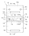
【図2】 前記取付具を示す正面図である。
【図3】 前記取付具を示す側面図である。
【図4】 前記取付具を示す平面図である。
【図5】 前記取付具を示す底面図である。
【図6】 前記取付具を示す背面図である。
【図7】 図1のVII−VII線における断面図である。
【図8】 前記取付具の弾性係合部を示す拡大断面図である。
【図9】 図2のIX−IX線における拡大断面図である。
【図10】 前記第一実施例におけるパネル状材の取付構造を示す断面図である。
【図11】 前記パネル状材の取付構造の一部を示す拡大断面図である。
【図12】 本発明に対する参考例における取付具を示す正面図である。
【図13】 図12のXIII−XIII線における断面図である。
【図14】 前記参考例の取付具の上側弾性係合部付近を示す拡大断面図である。
【図15】 前記参考例の取付具の下側弾性係合部付近を示す拡大断面図である。
【図16】 前記参考例におけるパネル状材の取付構造を示す断面図である。
【符号の説明】
1 取付具
2 パネル状材
3 取付具本体部
4 弾性係合部
6 パネル状材受け部
7 位置決め突起
8 基部
9 上側立ち上がり部
10 上側湾曲部
11 下側立ち上がり部
12 下側湾曲部
13 位置決め穴
14,15,16 係合片
20,21,22 溝部
23 支持材
24 上側弾性係合部
25 下側弾性係合部
27 上側立ち上がり部
29 係合片
31 下側立ち上がり部
33 係合片[0001]
BACKGROUND OF THE INVENTION
The present invention relates to a panel-like material fixture and attachment structure for attaching panel-like materials such as curtains, exterior materials, exterior decorative plate materials, and inner wall materials of buildings such as houses to support materials such as base materials.
[0002]
[Prior art]
Conventionally, as a mounting structure for attaching the panel-like material as described above to a support material that rises in the vertical direction, such as a base material, after attaching the fixture to the support material with nails, screws, etc., the panel-like material is further attached to the fixture. An attachment structure in which a panel-like material is attached to the base material via the attachment by attaching a material is often used.
[0003]
[Problems to be solved by the invention]
However, in the conventional panel-shaped material mounting structure, there is a problem that the panel-shaped material is troublesome to mount, and that the panel-shaped material is not sufficiently attached to the support material.
[0004]
The present invention has been made in view of such conventional circumstances, and one object of the present invention is to attach panel-like materials such as curtain plates, exterior materials, exterior decorative plate materials, and inner wall materials of buildings such as houses. It is an object of the present invention to provide a panel-like material fixture and a mounting structure capable of simply and quickly.
[0005]
Another object of the present invention is to provide a panel-shaped material fixture and a mounting structure capable of increasing the mounting strength of the panel-shaped material with respect to a support material.
[0006]
Another object of the present invention is to provide a panel-shaped material fixture and a mounting structure capable of preventing looseness and loosening of the panel-shaped material with respect to the support material.
[0007]
Still other objects of the present invention will become apparent from the following description.
[0008]
[Means for Solving the Problems]
A panel-like material fixture according to the present invention is a panel-like material fixture for attaching a panel-like material to a support material, wherein the panel-like material is provided with two grooves extending laterally on the back side. The lower side wall surface of the upper groove portion and the upper side wall surface of the lower groove portion are spread in the thickness direction of the panel-like material,
A fixture main body attached to the support material, and an elastic engagement part formed by processing a relatively elastic metal plate;
The elastic engagement portion is substantially extended in parallel with the panel-shaped material, and a base portion attached to the fixture main body portion, and rises in the thickness direction of the panel-shaped material from the upper end of the base portion. that the upper rising portion, and a lower rising portion which rises from the lower end of the base portion in a thickness direction of the panel-like member, a portion of the rising portion, the other so as to be left far side is cut from the support member has an engagement piece having an elastic formed by cutting and raising the rising portion, and a curved portion, respectively from the front end of the upper and lower rising portion is curved on the side opposite to the other of the rising portion, the elastic engagement Of the portion, the portion constituted by the base and the rising portion has a U-shaped cross section, and the engagement piece is curved so as to be concave in the cut and raised direction,
The upper and lower rising portions penetrate into the two groove portions, respectively, and the upper and lower rising portions sandwich the portion between the two groove portions of the panel-like material. When the material is pushed into the support material side, the engagement piece is pushed by the panel-like material and elastically deformed, and the front end portion of the engagement piece is pushed against the side wall surface of the groove portion. To do.
[0009]
The panel-shaped material mounting structure according to the present invention is a panel-shaped material mounting structure in which the panel-shaped material is attached to the support material via a fixture.
The panel-like material is provided with two groove portions extending in the lateral direction on the back surface side, and the lower side wall surface of the upper groove portion and the upper side wall surface of the lower groove portion are formed of the panel-like material. It spreads roughly in the thickness direction,
The fixture includes a fixture main body portion attached to the support member, and an elastic engagement portion formed by processing a relatively elastic metal plate.
The elastic engagement portion extends substantially parallel to the panel-like material, and has a base portion attached to the fixture main body portion, and an upper rising that rises from the upper end of the base portion in the thickness direction of the panel-like material. parts and, a lower rising portion which rises from the lower end of the base portion in a thickness direction of the panel-like member, a portion of the rising portion, the other of the rising portion as the side farther from the support member is left off to an engagement piece having an elastic formed by cutting and bending, having said upper and a curved portion that is curved on the side opposite to the respective the front end of the lower rising portion other of said rising portion, of the elastic engagement portion The portion constituted by the base and the rising portion of the base has a U-shaped cross section, and the engagement piece is curved so as to be concave in the cut and raised direction,
The upper and lower rising portions penetrate into the two groove portions, respectively, and the upper and lower rising portions sandwich the portion between the two groove portions of the panel-like material. When the material is pushed into the support material side, the engagement piece is pushed and elastically deformed by the panel-like material, and the front end portion of the engagement piece is pressed against the side wall surface of the groove portion. It is a feature.
[0010]
In the present invention, the fixture is first attached to the support material. Next, the panel-like material is pushed into the support material side in a state of matching with an appropriate positional relationship. Then, the engagement piece is pressed by the panel-like material and elastically deformed, and the tip end portion of the engagement piece is pressed against the side wall surface of each groove portion extending in the generally thickness direction of the panel-like material. Here, since the engagement piece protrudes from the side far from the support material to the near side and is curved so as to be concave with respect to the predetermined surface of the panel material, the direction in which the panel material is separated from the support material When it is going to be moved, the front end portion of the engagement piece tends to bite into the side wall surface of each groove portion, so that the panel-like material cannot move in the direction away from the support material. Therefore, the panel-like material is firmly and securely attached to the support material via the fixture.
[0011]
Also, in this panel-like material mounting structure, the panel-like material can be attached to the support material simply by pushing the panel-like material into the support material side, so the panel-like material can be easily and quickly attached. Can do.
[0012]
Furthermore, since the engagement piece is elastically pressed against the panel-shaped material, it is possible to prevent the panel-shaped material from being loosened or loosened against the support material.
[0013]
DETAILED DESCRIPTION OF THE INVENTION
Hereinafter, the present invention will be described based on embodiments shown in the drawings.
[0014]
【Example】
1 to 11 show a first embodiment of the present invention, in which FIGS. 1 to 9 show a
[0015]
The
[0016]
The
[0017]
In the present embodiment, the
[0018]
The upper rising
[0019]
The upper rising
[0020]
An appropriate number of mounting
[0021]
The panel-
[0022]
Next, the attachment structure of the panel-shaped
[0023]
In this embodiment, first, a
[0024]
Next, the panel-like
[0025]
In the present embodiment, the two
[0026]
In the mounting structure of the panel-shaped
[0027]
Furthermore, since the
[0028]
In the present embodiment, the upper
[0029]
12 to 16 show a reference example for the present invention, among which FIGS. 12 to 15 show a
[0030]
In the present reference example, the
[0031]
The upper and lower
[0032]
As in the case of the first embodiment, the
[0033]
The panel-
[0034]
Next, the mounting structure of the panel-
[0035]
Next, the panel-like
[0036]
Also in this reference example, the panel-
[0037]
Furthermore, since the
[0038]
Further, in this reference example, it is not necessary to provide a groove for allowing the upper and lower
[0039]
Also in this reference example, the constituent materials of the fixture
[0040]
The front in you施例, but the panel-shaped
[0041]
In the present invention, the shape of the portion receiving the elastic engagement portion and the panel-like member is limited to the
[0042]
Also, before you施例, and a
[0043]
The front you施例is panel-
[0044]
【The invention's effect】
As described above, the present invention
(A) The panel-like material can be easily and quickly attached.
(B) The mounting strength of the panel-like material to the support material can be increased.
(C) The panel-like material can be prevented from rattling and loosening against the support material.
It is possible to obtain excellent effects such as.
[Brief description of the drawings]
FIG. 1 is a perspective view showing a fixture in a first embodiment of the present invention.
FIG. 2 is a front view showing the fixture.
FIG. 3 is a side view showing the fixture.
FIG. 4 is a plan view showing the fixture.
FIG. 5 is a bottom view showing the fixture.
FIG. 6 is a rear view showing the fixture.
7 is a cross-sectional view taken along line VII-VII in FIG.
FIG. 8 is an enlarged cross-sectional view showing an elastic engagement portion of the fixture.
FIG. 9 is an enlarged cross-sectional view taken along line IX-IX in FIG.
FIG. 10 is a cross-sectional view showing a panel-shaped material mounting structure in the first embodiment.
FIG. 11 is an enlarged cross-sectional view showing a part of the panel-shaped material mounting structure.
FIG. 12 is a front view showing a fixture in a reference example for the present invention.
13 is a cross-sectional view taken along line XIII-XIII in FIG.
FIG. 14 is an enlarged cross-sectional view showing the vicinity of an upper elastic engagement portion of the fixture of the reference example.
FIG. 15 is an enlarged cross-sectional view showing the vicinity of a lower elastic engagement portion of the fixture of the reference example.
FIG. 16 is a cross-sectional view showing a panel-shaped material mounting structure in the reference example.
[Explanation of symbols]
DESCRIPTION OF
Claims (6)
前記支持材に取り付けられる取付具本体部と、比較的に弾性に富む金属板を加工してなる弾性係合部とを有してなり、
前記弾性係合部は、大略パネル状材と平行に広がることとなるようにして前記取付具本体部に取り付けられた基部と、この基部の上端から前記パネル状材の厚さ方向に立ち上がる上側立ち上がり部と、前記基部の下端から前記パネル状材の厚さ方向に立ち上がる下側立ち上がり部と、前記立ち上がり部の一部を、前記支持材から遠い側が切り残されるようにして他方の前記立ち上がり部側に切り起こしてなる弾性を有する係合片と、前記上側および下側立ち上がり部の先端からそれぞれ他方の前記立ち上がり部と反対側に湾曲された湾曲部とを有し、前記弾性係合部のうちの前記基部および前記立ち上がり部で構成される部分は横断面コの字状をなし、前記係合片は切り起こし方向に凹となるように湾曲されており、
前記上側および下側立ち上がり部が前記2本の溝部にそれぞれ侵入し、前記上側および下側立ち上がり部が前記パネル状材の前記2本の溝部間の部分を挟むこととなるようにして前記パネル状材が前記支持材側に押し込まれると、前記係合片が前記パネル状材に押されて弾性変形し、前記係合片の先端部が前記溝部の前記側壁面に押圧されることを特徴とするパネル状材の取付具。In the panel-shaped material fixture for mounting the panel-shaped material to the support material, the panel-shaped material is provided with two groove portions extending in the lateral direction on the back side, and the lower side of the upper groove portion. The wall surface and the upper side wall surface of the lower groove portion are spread in the thickness direction of the panel-shaped material,
A fixture main body attached to the support material, and an elastic engagement part formed by processing a relatively elastic metal plate;
The elastic engagement portion extends substantially parallel to the panel-like material, and has a base portion attached to the fixture main body portion, and an upper rising that rises from the upper end of the base portion in the thickness direction of the panel-like material. parts and, a lower rising portion which rises from the lower end of the base portion in a thickness direction of the panel-like member, a portion of the rising portion, the other of the rising portion as the side farther from the support member is left off to an engagement piece having an elastic formed by cutting and bending, having said upper and a curved portion that is curved on the side opposite to the respective the front end of the lower rising portion other of said rising portion, of the elastic engagement portion The portion constituted by the base and the rising portion of the base has a U-shaped cross section, and the engagement piece is curved so as to be concave in the cut and raised direction,
The upper and lower rising portions penetrate into the two groove portions, respectively, and the upper and lower rising portions sandwich the portion between the two groove portions of the panel-like material. When the material is pushed into the support material side, the engagement piece is pushed by the panel-like material and elastically deformed, and the front end portion of the engagement piece is pushed against the side wall surface of the groove portion. Panel-like material fixture.
この係合片の先端部が前記パネル状材の下側の前記溝部の、前記パネル状材の大略厚さ方向に広がっている下側の側壁面に押圧される請求項1記載のパネル状材の取付具。A further part of the lower rising portion is further provided with an engagement piece having elasticity formed by cutting and raising downward so that the side far from the support material is left uncut.
The panel-like material according to claim 1 , wherein a tip end portion of the engagement piece is pressed against a lower side wall surface of the groove portion on the lower side of the panel-like material and extending in a generally thickness direction of the panel-like material. Fittings.
前記パネル状材は裏面側にそれぞれ横方向に延びる2本の溝部を設けられていて、上側の前記溝部の下側の側壁面および下側の前記溝部の上側の側壁面が該パネル状材の大略厚さ方向に広がっており、
前記取付具は、前記支持材に取り付けられる取付具本体部と、比較的に弾性に富む金属板を加工してなる弾性係合部とを有してなり、
前記弾性係合部は、大略パネル状材と平行に広がることとなるようにして前記取付具本体部に取り付けられた基部と、この基部の上端から前記パネル状材の厚さ方向に立ち上がる上側立ち上がり部と、前記基部の下端から前記パネル状材の厚さ方向に立ち上がる下側立ち上がり部と、前記立ち上がり部の一部を、前記支持材から遠い側が切り残されるようにして他方の前記立ち上がり部側に切り起こしてなる弾性を有する係合片と、前記上側および下側立ち上がり部の先端からそれぞれ他方の前記立ち上がり部と反対側に湾曲された湾曲部とを有し、前記弾性係合部のうちの前記基部および前記立ち上がり部で構成される部分は横断面コの字状をなし、前記係合片は切り起こし方向に凹となるように湾曲されており、
前記上側および下側立ち上がり部が前記2本の溝部にそれぞれ侵入し、前記上側および下側立ち上がり部が前記パネル状材の前記2本の溝部間の部分を挟むこととなるようにして前記パネル状材が前記支持材側に押し込まれることにより、前記係合片が前記パネル状材に押されて弾性変形し、前記係合片の先端部が前記溝部の前記側壁面に押圧されていることを特徴とするパネル状材の取付構造。In the mounting structure of the panel-like material that attaches the panel-like material to the support material via the fixture,
The panel-like material is provided with two groove portions extending in the lateral direction on the back surface side, and the lower side wall surface of the upper groove portion and the upper side wall surface of the lower groove portion are formed of the panel-like material. It spreads roughly in the thickness direction,
The fixture includes a fixture main body portion attached to the support member, and an elastic engagement portion formed by processing a relatively elastic metal plate.
The elastic engagement portion extends substantially parallel to the panel-like material, and has a base portion attached to the fixture main body portion, and an upper rising that rises from the upper end of the base portion in the thickness direction of the panel-like material. parts and, a lower rising portion which rises from the lower end of the base portion in a thickness direction of the panel-like member, a portion of the rising portion, the other of the rising portion as the side farther from the support member is left off to an engagement piece having an elastic formed by cutting and bending, having said upper and a curved portion that is curved on the side opposite to the respective the front end of the lower rising portion other of said rising portion, of the elastic engagement portion The portion constituted by the base and the rising portion of the base has a U-shaped cross section, and the engagement piece is curved so as to be concave in the cut and raised direction,
The upper and lower rising portions penetrate into the two groove portions, respectively, and the upper and lower rising portions sandwich the portion between the two groove portions of the panel-like material. When the material is pushed into the support material side, the engagement piece is pushed and elastically deformed by the panel-like material, and the front end portion of the engagement piece is pressed against the side wall surface of the groove portion. A mounting structure for the panel material.
この係合片の先端部が前記パネル状材の下側の前記溝部の、前記パネル状材の大略厚さ方向に広がっている下側の側壁面に押圧されている請求項4記載のパネル状材の取付構造。The elastic engagement portion, a portion of the lower rising part, so as to leave cut side farther from the support member, further comprising a engaging piece having elasticity formed by cutting and bending downward,
The panel-like shape according to claim 4, wherein a tip end portion of the engagement piece is pressed against a lower side wall surface of the groove portion on the lower side of the panel-like material and extending in a generally thickness direction of the panel-like material. Material mounting structure.
Priority Applications (1)
| Application Number | Priority Date | Filing Date | Title |
|---|---|---|---|
| JP2000221611A JP3662481B2 (en) | 2000-07-24 | 2000-07-24 | Panel-shaped material fixture and mounting structure |
Applications Claiming Priority (1)
| Application Number | Priority Date | Filing Date | Title |
|---|---|---|---|
| JP2000221611A JP3662481B2 (en) | 2000-07-24 | 2000-07-24 | Panel-shaped material fixture and mounting structure |
Publications (2)
| Publication Number | Publication Date |
|---|---|
| JP2002038694A JP2002038694A (en) | 2002-02-06 |
| JP3662481B2 true JP3662481B2 (en) | 2005-06-22 |
Family
ID=18715981
Family Applications (1)
| Application Number | Title | Priority Date | Filing Date |
|---|---|---|---|
| JP2000221611A Expired - Lifetime JP3662481B2 (en) | 2000-07-24 | 2000-07-24 | Panel-shaped material fixture and mounting structure |
Country Status (1)
| Country | Link |
|---|---|
| JP (1) | JP3662481B2 (en) |
-
2000
- 2000-07-24 JP JP2000221611A patent/JP3662481B2/en not_active Expired - Lifetime
Also Published As
| Publication number | Publication date |
|---|---|
| JP2002038694A (en) | 2002-02-06 |
Similar Documents
| Publication | Publication Date | Title |
|---|---|---|
| JP3490674B2 (en) | Exterior wall construction structure | |
| US6637172B2 (en) | Clip for attachment to flanges of structural steel | |
| JP2001336269A (en) | Fastening fitting | |
| JP3662481B2 (en) | Panel-shaped material fixture and mounting structure | |
| JP2003147937A (en) | Fittings of panel-like material for wall | |
| JP3420933B2 (en) | Panel mounting bracket | |
| JP2003293573A (en) | Decorated material mounting implement and decorated material mounting structure using the same | |
| JP2503755Y2 (en) | Joint cover fitting | |
| JPH0715953Y2 (en) | Steel base material stopper | |
| JP4132352B2 (en) | Panel-shaped material fixture, mounting structure and mounting method | |
| JPH0645532Y2 (en) | Field fittings | |
| JP4729190B2 (en) | Gutter support | |
| JP4359338B2 (en) | Fitting | |
| CA2106801C (en) | Electrical box assembly with mounting bracket | |
| JPH075148Y2 (en) | Scraper | |
| JP2001098741A (en) | Metal fitting for mounting outer decorative board | |
| JP2548317Y2 (en) | Eaves back ceiling panel | |
| JP2001020498A (en) | Metal fittings for architectural decoration board and fitting structure using the metal fittings | |
| JP2005054424A (en) | Fixture and mounting method | |
| JPH053765Y2 (en) | ||
| US20070194195A1 (en) | Support bracket and kit of parts for a support assembly | |
| JPH08302847A (en) | Heat insulating material fixture consisting of elastic metallic thin plate | |
| JP4267169B2 (en) | Steel field edge connection structure and steel field edge connection method | |
| JP2002147008A (en) | Installing structure of modesty panel, fitting therefor, and modesty panel | |
| JP3189682U (en) | Tile mounting material |
Legal Events
| Date | Code | Title | Description |
|---|---|---|---|
| A131 | Notification of reasons for refusal |
Free format text: JAPANESE INTERMEDIATE CODE: A131 Effective date: 20040928 |
|
| A521 | Written amendment |
Free format text: JAPANESE INTERMEDIATE CODE: A523 Effective date: 20041112 |
|
| A131 | Notification of reasons for refusal |
Free format text: JAPANESE INTERMEDIATE CODE: A131 Effective date: 20041214 |
|
| A521 | Written amendment |
Free format text: JAPANESE INTERMEDIATE CODE: A523 Effective date: 20050126 |
|
| TRDD | Decision of grant or rejection written | ||
| A01 | Written decision to grant a patent or to grant a registration (utility model) |
Free format text: JAPANESE INTERMEDIATE CODE: A01 Effective date: 20050228 |
|
| A61 | First payment of annual fees (during grant procedure) |
Free format text: JAPANESE INTERMEDIATE CODE: A61 Effective date: 20050323 |
|
| R150 | Certificate of patent or registration of utility model |
Free format text: JAPANESE INTERMEDIATE CODE: R150 Ref document number: 3662481 Country of ref document: JP Free format text: JAPANESE INTERMEDIATE CODE: R150 |
|
| FPAY | Renewal fee payment (event date is renewal date of database) |
Free format text: PAYMENT UNTIL: 20080401 Year of fee payment: 3 |
|
| FPAY | Renewal fee payment (event date is renewal date of database) |
Free format text: PAYMENT UNTIL: 20110401 Year of fee payment: 6 |
|
| R250 | Receipt of annual fees |
Free format text: JAPANESE INTERMEDIATE CODE: R250 |
|
| FPAY | Renewal fee payment (event date is renewal date of database) |
Free format text: PAYMENT UNTIL: 20140401 Year of fee payment: 9 |
|
| R250 | Receipt of annual fees |
Free format text: JAPANESE INTERMEDIATE CODE: R250 |
|
| R250 | Receipt of annual fees |
Free format text: JAPANESE INTERMEDIATE CODE: R250 |
|
| R250 | Receipt of annual fees |
Free format text: JAPANESE INTERMEDIATE CODE: R250 |
|
| R250 | Receipt of annual fees |
Free format text: JAPANESE INTERMEDIATE CODE: R250 |
|
| R250 | Receipt of annual fees |
Free format text: JAPANESE INTERMEDIATE CODE: R250 |
|
| R250 | Receipt of annual fees |
Free format text: JAPANESE INTERMEDIATE CODE: R250 |
|
| R250 | Receipt of annual fees |
Free format text: JAPANESE INTERMEDIATE CODE: R250 |
|
| R250 | Receipt of annual fees |
Free format text: JAPANESE INTERMEDIATE CODE: R250 |
|
| EXPY | Cancellation because of completion of term |