JP3662425B2 - Liquid filled container - Google Patents
Liquid filled container Download PDFInfo
- Publication number
- JP3662425B2 JP3662425B2 JP27574498A JP27574498A JP3662425B2 JP 3662425 B2 JP3662425 B2 JP 3662425B2 JP 27574498 A JP27574498 A JP 27574498A JP 27574498 A JP27574498 A JP 27574498A JP 3662425 B2 JP3662425 B2 JP 3662425B2
- Authority
- JP
- Japan
- Prior art keywords
- liquid
- container
- opening
- container body
- conduit
- Prior art date
- Legal status (The legal status is an assumption and is not a legal conclusion. Google has not performed a legal analysis and makes no representation as to the accuracy of the status listed.)
- Expired - Lifetime
Links
Images
Landscapes
- Bag Frames (AREA)
Description
【0001】
【発明の属する技術分野】
本発明は、液体の充填を効率よく行うとともに、使用目的に応じた液量を注出できる液体充填容器に関する。
【0002】
【従来の技術】
この種の液体充填容器として、フレキシブルフィルムで作った容器本体と、口部および導管部を有し容器本体の開口部に固着された取出装置とを有する構造のものは知られている。容器本体としては、充填される液体の性質に応じて、ガゼットパウチ、スタンディングパウチ、フラットパウチ等の形態のものが使用されている。
たとえば、実用新案登録公報第12546773号には、フレキシブルフィルムで作った容器本体と、口部および導管部を有し容器本体の開口部に固着された取出装置とを有し、容器本体に設けた取出装置の導管部の下端を閉じ、導管部の容器本体の両面側でかつ封着部分に近い部位に開口を設けた液体充填容器が記載されている。
【0003】
上記液体充填容器は、取出装置の口部に連なる導管部の壁面に開口を設けるとともに導管部の下端面を閉じているので、手で持ってそのまま傾けることで充填された液体を導管部の開口から口部を通して外部に注出することができ、容器の開口に対応した部位を指で押圧することで導管部に設けた開口を開閉制御することで注出量を調節することができる。
【0004】
【発明が解決しようとする課題】
しかしながら、上記液体充填容器は、取出装置の口部に連なる導管部の下端面を閉じた構造となっているので、充填ノズルを通して液体を液体充填容器の内部に充填しようとする際、充填される液体に対して導管部の下端面が抵抗となり、液体の充填速度を低下させたり、充填される液体に泡立ちを生じさせてしまうという問題点がある。
【0005】
本発明は上記した点に鑑みてなされたもので、液体の充填を効率よく行うとともに、使用目的に応じた液量を注出することができる液体充填容器を提供することを目的とする。
【0006】
【課題を解決するための手段】
本発明の液体充填容器は、フレキシブルフィルムで作った容器本体と、口部および導管部を有し容器本体の開口部に固着された取出装置とを有し、取出装置の導管部の下端を先窄まり状に偏平とした狭搾部分とし、狭搾部分は、指の腹に対応した凹曲面の偏平部を有し、偏平部に導管内部に連通する開口を設けて構成される。
【0007】
【発明の実施の形態】
以下本発明の実施の形態を図面を参照して説明する。
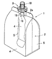
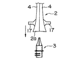
図1において符号1は液体充填容器を示し、この液体充填容器1は、たとえば食用油や洗剤を収容するのに利用される。
上記液体充填容器1は、図1に示すように、上方開口のガセット形容器本体2と、このガセット形容器本体2の開口部2aに固着された取出装置3とから構成されている。
【0008】
上記ガセット形容器本体2は、両面部分4,4と、これら両面部分4,4の間に折り込み端が内方に位置するように配置されたガセット部分5,5を有する。ガセット形容器本体2の両面部分4,4およびガセット部分5,5は、ガセット形容器本体2がフレキシブル性を具有するように積層プラスチックフィルム6によって形成されている。
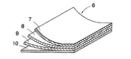
【0009】
上記積層プラスチックフィルム6は、図2に示すように、ポリエステルフィルム7、アルミホイル8、延伸ナイロンフィルム9およびポリエチレンフィルム10を積層することで形成される。
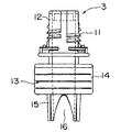
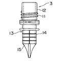
【0010】
上記取出装置3は、図3および図4に示すように、ねじ部11を設けた口部12と、この口部10に一体に連接される導管部13とを有する。導管部13は、ガセット形容器本体2に接着される接合部分14とこの接合部分14より下方に延びる狭搾部分15を有する。狭搾部分15は、接合部分14から下端方向に先窄まり状に偏平とした形状をなしている。狭搾部分15の偏平面は、指の腹に対応した凹曲面であり、凹曲面に開口16が形成されている。この開口16は、狭搾部分15の下端を略U形に切り欠くことて形成されるが、狭搾部分15の強度を高めるために、狭搾部分15の下端に橋絡部を設けることもできる。
【0011】
上記取出装置3をガセット形容器本体2に装着するには、図5に示すように、取出装置3を狭搾部分15が上側に位置するように配置し、その取出装置3の上方にガセット形容器本体2を開口端2aが下側に位置するように配置する。そして、ガセット形容器本体2の両面部分4,4の開口端側をバキュームパッド17,17で互いに離れる方向に引っ張ることで広口の開口を形成し、ガセット形容器本体2を矢印で示す方向に移動し、広口の開口に取出装置3を挿入することで行う。
なお、図1において、符号18は口部12のねじ部11に螺着されるキャップである。
【0012】
液体充填容器1に洗剤のような液体を充填するには、図示しない充填ノズルを取出装置3の口部12に装着し、液体を充填ノズルを通して液体充填容器の内部に導入することで行う。この場合、導管部13の狭搾部分15が、下端方向に先窄まり状に偏平とした形状をなし、狭搾部分15の凹曲面に開口16が形成されているので、口部12から導管部13に導かれる液体は、狭搾部分15の凹曲面に沿ってなだらかに流れ、開口16から液体充填容器1に充填される。そのため、液体は、導管部13の狭搾部分15において抵抗を受けることがほとんどなく、従来のもののように、充填速度を低下させたり、液体に泡立ちが生じさせたりすることがない。
【0013】
液体充填容器1に充填された液体を取り出すには、キャップ18を口部12から取り外し、液体充填容器1を手で持って傾け、液体を開口16から導管部13を通して口部10から注ぎ出すことで行なう。液体の注ぎ出し量は、容器本体2の両面の導管部13の狭搾部分15に設けた開口16に対応した部位を押圧することで狭搾部分15に設けた開口16の開閉を制御することで調節することができる。
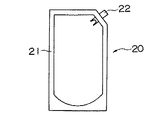
【0014】
図6は本発明による液体充填容器の他の実施の形態を示す。図6に示す液体充填容器20は、容器本体21と取出装置22とから構成されている。容器本体21は、両面部分と底部分とを有するスタンディング形容器である。上記液体充填容器20は、食用油を収容するのに適している。上記液体充填容器20において、取出装置22の構成は図1に示す液体充填容器1の取出装置3と同じである。
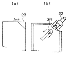
【0015】
上記取出装置22をスタンディング形容器本体21に装着するには、図7(a)に示すように、スタンディング形容器本体21の開口端の隅部23を図示しない切断具によりカットし、図7(b)に示すように、スタンディング形容器本体21のカットした部分に近い部位をバキュームパッド24,24で互いに離れる方向に引っ張ることで広口の開口を形成し、取出装置22を矢印で示す方向に動かして、取出装置22をスタンディング形容器本体21の開口に挿入し、取出装置22をスタンディング形容器本体21にヒートシール加工することで行う。
【0016】
液体充填容器20に封入された食用油を取り出すには、キャップ18を口部12から取り外し、液体充填容器1を手で持って傾け、液体を開口16から導管部13を通して口部10から注ぎ出すことで行なうが、容器本体21の両面の導管部13の狭搾部分15に設けた開口16に対応した部位を押圧することで狭搾部分15に設けた開口16の開閉を制御することで食用油の注ぎ出し量を調節できる。そのため、従来のもののように、食用油を充填した容器を手で持って傾ける使用始めに、容器から多量の油がフライパンに注ぎ出されることがなく、フライパンに注ぎ出される油が下部の火により引火する危険性を防ぐことができる。
【0017】
【発明の効果】
以上述べたように、本発明によれば、取出装置の導管部の下端を先窄まり状に偏平とした狭搾部分とし、狭搾部分は、指の腹に対応した凹曲面の偏平部を有し、偏平部に導管内部に連通する開口を設けたことで、液体を液体充填容器に充填する際の液体の泡立ちの発生を防ぐことができる。
【図面の簡単な説明】
【図1】本発明による液体充填容器の一部を破砕して示す斜視図。
【図2】本発明による液体充填容器の容器本体を構成するフレキシブルフィルムの一部を示す図。
【図3】 本発明による液体充填容器の取出装置の正面図。
【図4】本発明による液体充填容器の取出装置の側面図。
【図5】図1に示す液体充填容器の取出装置を容器本体に取付ける段階を示す図。
【図6】本発明による液体充填容器の他の実施の形態を示す図。
【図7】図6に示す液体充填容器の取出装置を容器本体に取付ける段階を示す図。
【符号の説明】
1 液体充填容器
2 容器本体
3 取出装置
12 口部
13 導管部
15 狭搾部
16 開口[0001]
BACKGROUND OF THE INVENTION
The present invention relates to a liquid filling container capable of efficiently filling a liquid and dispensing a liquid amount according to the purpose of use.
[0002]
[Prior art]
As this type of liquid-filled container, there is known a structure having a container body made of a flexible film and a take-out device having a mouth part and a conduit part and fixed to the opening of the container body. As a container main body, the thing of forms, such as a gusset pouch, a standing pouch, a flat pouch, is used according to the property of the liquid with which it is filled.
For example, Utility Model Registration Publication No. 125546773 has a container body made of a flexible film, and a take-out device fixed to the opening of the container body having a mouth portion and a conduit portion, and provided in the container body. A liquid-filled container is described in which the lower end of the conduit portion of the take-out device is closed, and openings are provided on the both sides of the container body of the conduit portion and close to the sealing portion.
[0003]
The liquid filling container is provided with an opening in the wall surface of the conduit portion connected to the mouth portion of the take-out device and the lower end surface of the conduit portion is closed, so that the liquid filled by inclining as it is held by hand is opened in the conduit portion. It is possible to pour out to the outside through the mouth portion, and the amount of pour can be adjusted by controlling opening and closing of the opening provided in the conduit portion by pressing a portion corresponding to the opening of the container with a finger.
[0004]
[Problems to be solved by the invention]
However, since the liquid filling container has a structure in which the lower end surface of the conduit portion connected to the mouth portion of the take-out device is closed, the liquid filling container is filled when trying to fill the liquid into the liquid filling container through the filling nozzle. There is a problem in that the lower end surface of the conduit portion becomes a resistance against the liquid, and the filling speed of the liquid is reduced, or bubbles are generated in the filled liquid.
[0005]
The present invention has been made in view of the above points, and an object of the present invention is to provide a liquid-filled container capable of efficiently filling a liquid and dispensing a liquid amount according to the purpose of use.
[0006]
[Means for Solving the Problems]
The liquid-filled container of the present invention has a container body made of a flexible film, and a take-out device that has a mouth and a conduit and is fixed to the opening of the container body. The squeezed flattened portion is a squeezed portion, and the squeezed portion has a concave curved flat portion corresponding to the belly of the finger and is provided with an opening communicating with the inside of the conduit in the flat portion.
[0007]
DETAILED DESCRIPTION OF THE INVENTION
Embodiments of the present invention will be described below with reference to the drawings.
In FIG. 1,
As shown in FIG. 1, the liquid-filled
[0008]
The gusset-
[0009]
The laminated
[0010]
As shown in FIGS. 3 and 4, the take-out
[0011]
In order to mount the take-out
In FIG. 1,
[0012]
In order to fill the
[0013]
In order to take out the liquid filled in the
[0014]
FIG. 6 shows another embodiment of the liquid filling container according to the present invention. The
[0015]
To attach the take-out
[0016]
In order to take out the cooking oil enclosed in the
[0017]
【The invention's effect】
As described above, according to the present invention, the lower end of the conduit portion of the extraction device is a narrowed portion that is flattened in a tapered shape, and the narrowed portion is a flat portion of a concave curved surface corresponding to the belly of the finger. And by providing an opening communicating with the inside of the conduit in the flat portion, it is possible to prevent the occurrence of bubbling of the liquid when the liquid is filled in the liquid filling container.
[Brief description of the drawings]
FIG. 1 is a perspective view showing a part of a liquid filling container according to the present invention in a crushed state.
FIG. 2 is a view showing a part of a flexible film constituting a container body of a liquid filling container according to the present invention.
FIG. 3 is a front view of the liquid filling container take-out device according to the present invention.
FIG. 4 is a side view of a liquid filling container take-out device according to the present invention.
FIG. 5 is a view showing a stage of attaching the liquid filling container take-out device shown in FIG. 1 to the container main body.
FIG. 6 is a view showing another embodiment of the liquid filling container according to the present invention.
7 is a view showing a stage of attaching the liquid filling container take-out device shown in FIG. 6 to the container main body.
[Explanation of symbols]
DESCRIPTION OF
Claims (3)
Priority Applications (1)
| Application Number | Priority Date | Filing Date | Title |
|---|---|---|---|
| JP27574498A JP3662425B2 (en) | 1998-09-29 | 1998-09-29 | Liquid filled container |
Applications Claiming Priority (1)
| Application Number | Priority Date | Filing Date | Title |
|---|---|---|---|
| JP27574498A JP3662425B2 (en) | 1998-09-29 | 1998-09-29 | Liquid filled container |
Publications (2)
| Publication Number | Publication Date |
|---|---|
| JP2000103438A JP2000103438A (en) | 2000-04-11 |
| JP3662425B2 true JP3662425B2 (en) | 2005-06-22 |
Family
ID=17559800
Family Applications (1)
| Application Number | Title | Priority Date | Filing Date |
|---|---|---|---|
| JP27574498A Expired - Lifetime JP3662425B2 (en) | 1998-09-29 | 1998-09-29 | Liquid filled container |
Country Status (1)
| Country | Link |
|---|---|
| JP (1) | JP3662425B2 (en) |
Cited By (1)
| Publication number | Priority date | Publication date | Assignee | Title |
|---|---|---|---|---|
| JP2011140329A (en) * | 2010-01-07 | 2011-07-21 | Toppan Printing Co Ltd | Baglike container |
Families Citing this family (6)
| Publication number | Priority date | Publication date | Assignee | Title |
|---|---|---|---|---|
| JP3604685B1 (en) | 2003-10-20 | 2004-12-22 | 株式会社細川洋行 | Packaging container |
| JP4476785B2 (en) * | 2004-11-10 | 2010-06-09 | 株式会社細川洋行 | Packaging container |
| JP4361497B2 (en) * | 2005-01-21 | 2009-11-11 | 株式会社細川洋行 | High viscosity food and beverage packaging container and high viscosity food and beverage packaging |
| JP4915089B2 (en) * | 2005-12-07 | 2012-04-11 | 大日本印刷株式会社 | Spout |
| JP5374693B2 (en) * | 2009-01-30 | 2013-12-25 | 株式会社フジシール | Spout and pouch with spout |
| JP6802088B2 (en) * | 2017-02-28 | 2020-12-16 | 花王株式会社 | Bag container with spout |
Family Cites Families (4)
| Publication number | Priority date | Publication date | Assignee | Title |
|---|---|---|---|---|
| JP2546773Y2 (en) * | 1991-11-15 | 1997-09-03 | 株式会社細川洋行 | Liquid refill container |
| JP2731758B2 (en) * | 1995-04-20 | 1998-03-25 | 日本キム株式会社 | Flow control container |
| JPH10236488A (en) * | 1997-02-20 | 1998-09-08 | Daiwa Gravure Co Ltd | Liquid removal device |
| JP2934611B2 (en) * | 1997-04-16 | 1999-08-16 | 日本キム株式会社 | Container |
-
1998
- 1998-09-29 JP JP27574498A patent/JP3662425B2/en not_active Expired - Lifetime
Cited By (1)
| Publication number | Priority date | Publication date | Assignee | Title |
|---|---|---|---|---|
| JP2011140329A (en) * | 2010-01-07 | 2011-07-21 | Toppan Printing Co Ltd | Baglike container |
Also Published As
| Publication number | Publication date |
|---|---|
| JP2000103438A (en) | 2000-04-11 |
Similar Documents
| Publication | Publication Date | Title |
|---|---|---|
| US6076967A (en) | Fillable disposable drink bag | |
| RU2001850C1 (en) | Package for fluid media | |
| JP2004515423A (en) | container | |
| ITMI941761A1 (en) | HOUSING OF CONTAINER CONTAINING A SINGLE FLEXIBLE INTERNAL CONTAINER WHOSE CONTENT CAN BE DELIVERED THROUGH | |
| JP3662425B2 (en) | Liquid filled container | |
| JP2745388B2 (en) | Liquid container | |
| JP2004513031A (en) | Liquid container | |
| JP3077751B2 (en) | Refill bag | |
| JP2546773Y2 (en) | Liquid refill container | |
| JP3745021B2 (en) | Easy-to-refill liquid dispensing container | |
| JPH10119992A (en) | Bag | |
| JP3789571B2 (en) | Bag body with excellent pouring properties | |
| JPH10291549A (en) | Storing body | |
| JP2003191967A (en) | Inner bag for bag-in-box | |
| JPH11314644A (en) | Simple self-supporting bag with faucet | |
| JP3737561B2 (en) | container | |
| JP3841875B2 (en) | Inner lid for liquid dispensing container with handling function | |
| JP3054641U (en) | Structure of packaging bag with measuring section | |
| JPH0356503Y2 (en) | ||
| JP3722385B2 (en) | Easy refill packaging bag | |
| JP6135849B2 (en) | Pouch container | |
| JP2001233360A (en) | Flexible bag | |
| JPS6330699Y2 (en) | ||
| JPH0589246U (en) | Freestanding bag with handle | |
| JP4135234B2 (en) | Storage stand for flexible bags with liquid |
Legal Events
| Date | Code | Title | Description |
|---|---|---|---|
| A977 | Report on retrieval |
Free format text: JAPANESE INTERMEDIATE CODE: A971007 Effective date: 20040707 |
|
| A131 | Notification of reasons for refusal |
Free format text: JAPANESE INTERMEDIATE CODE: A131 Effective date: 20040713 |
|
| A521 | Written amendment |
Free format text: JAPANESE INTERMEDIATE CODE: A523 Effective date: 20040909 |
|
| TRDD | Decision of grant or rejection written | ||
| A01 | Written decision to grant a patent or to grant a registration (utility model) |
Free format text: JAPANESE INTERMEDIATE CODE: A01 Effective date: 20050225 |
|
| A61 | First payment of annual fees (during grant procedure) |
Free format text: JAPANESE INTERMEDIATE CODE: A61 Effective date: 20050323 |
|
| R150 | Certificate of patent or registration of utility model |
Free format text: JAPANESE INTERMEDIATE CODE: R150 |
|
| FPAY | Renewal fee payment (event date is renewal date of database) |
Free format text: PAYMENT UNTIL: 20080401 Year of fee payment: 3 |
|
| FPAY | Renewal fee payment (event date is renewal date of database) |
Free format text: PAYMENT UNTIL: 20110401 Year of fee payment: 6 |
|
| FPAY | Renewal fee payment (event date is renewal date of database) |
Free format text: PAYMENT UNTIL: 20120401 Year of fee payment: 7 |
|
| FPAY | Renewal fee payment (event date is renewal date of database) |
Free format text: PAYMENT UNTIL: 20130401 Year of fee payment: 8 |
|
| FPAY | Renewal fee payment (event date is renewal date of database) |
Free format text: PAYMENT UNTIL: 20130401 Year of fee payment: 8 |
|
| FPAY | Renewal fee payment (event date is renewal date of database) |
Free format text: PAYMENT UNTIL: 20140401 Year of fee payment: 9 |
|
| R250 | Receipt of annual fees |
Free format text: JAPANESE INTERMEDIATE CODE: R250 |
|
| R250 | Receipt of annual fees |
Free format text: JAPANESE INTERMEDIATE CODE: R250 |
|
| R250 | Receipt of annual fees |
Free format text: JAPANESE INTERMEDIATE CODE: R250 |
|
| R250 | Receipt of annual fees |
Free format text: JAPANESE INTERMEDIATE CODE: R250 |
|
| R250 | Receipt of annual fees |
Free format text: JAPANESE INTERMEDIATE CODE: R250 |
|
| EXPY | Cancellation because of completion of term |