JP3661985B2 - Thermal printer device - Google Patents
Thermal printer device Download PDFInfo
- Publication number
- JP3661985B2 JP3661985B2 JP28294399A JP28294399A JP3661985B2 JP 3661985 B2 JP3661985 B2 JP 3661985B2 JP 28294399 A JP28294399 A JP 28294399A JP 28294399 A JP28294399 A JP 28294399A JP 3661985 B2 JP3661985 B2 JP 3661985B2
- Authority
- JP
- Japan
- Prior art keywords
- print information
- thermal
- macro
- micro
- head
- Prior art date
- Legal status (The legal status is an assumption and is not a legal conclusion. Google has not performed a legal analysis and makes no representation as to the accuracy of the status listed.)
- Expired - Lifetime
Links
Images

Landscapes
- Electronic Switches (AREA)
Description
【0001】
【発明の属する技術分野】
本発明は、白抜き文字でも良好な印字品質を得ることができるサーマルプリンタ装置に関する。
【0002】
【従来の技術】
サーマルプリンタは、サーマルヘッドを加熱することにより印字を得るという特性上、印字を行うとサーマルヘッドが蓄熱される。このサーマルヘッドの蓄熱により、印字データがない部分まで黒く印字されてしまうことがあり、印字品質が損ねるという問題がある。
【0003】
従来より、このような問題を解決するために、該当ドットや隣接ドットの過去の印字情報を参照し、サーマルヘッドの印字のためのエネルギーを制御することにより印字品質の劣化を補正してきた。また、マクロ的に見ると、サーマルヘッドの蓄熱状態をサーミスタにより監視し、その情報に基づいてサーマルヘッドに供給するエネルギーを制御するようにしている。
【0004】
また従来、サーマルプリンタで印字される印字内容は、文字やバーコードのような印字やベタの印字等が主流であった。しかし、近年、サーマルヘッドで印字される印字内容は、多種類に亘っているのが実情である。例えば、製品に貼る銘板ラベルのようにべた印字の中に微小な白抜き文字を形成するといったことか要求されてきている。
【0005】
【発明が解決しようとする課題】
サーマルプリンタの印字速度が遅い場合や印字内容が文字等のように印字率の少ないものであれば、過去数ラインの印字情報に基づいてサーマルヘッドのエルネギーを制御すればよかった。
【0006】
しかし、べた印字の中に微小な白抜き文字を2ms/ライン以上の高速印字により形成しようとした場合、従来のように過去数ラインの印字情報に基づいてサーマルヘッドを制御するだけでは、白抜き文字がつぶれてしまったりしていた。また、白抜き文字がつぶれないようにサーマルヘッドに供給するエネルギーを制御すると、印字開始時にべた印字すべき部分にかすれが発生してしまうという問題があった。
【0007】
そこで、過去の多くの印字情報に基づいて、サーマルヘッドに供給するエネルギーを制御しようとすると、メモリが多く必要になってしまい、ハードウェアが大規模なものになってしまうという問題があった。
【0008】
また、ヘッドサーミスタの情報を印字エネルギーに反映させる方法では、2ms/ライン以上といった高速印字になると、サーミスタが反応する前に白抜き文字に印字つぶれが発生して、インクリボンの熱皺が発生したりするといったような問題が発生する。
【0009】
本発明は上記の点に鑑みてされたもので、その目的は、べた印字の中の白抜き文字でも良好な印字品質を得ることができるサーマルプリンタ装置を提供することにある。
【0011】
【課題を解決するための手段】
請求項1記載の発明は、発熱素子を複数配置したラインサーマルヘッドに通電し、その通電により発生した熱によって、インクリボンのインクを用紙に溶融または昇華させるサーマルプリンタにおいて、隣接素子も含めた過去数ラインのミクロ印字情報及び該当素子の過去数百ライン以上のマクロ印字情報を記憶する履歴メモリと、この履歴メモリから読み出されたミクロ印字情報及びマクロ印字情報を入力し、上記サーマルヘッドの通電時間を示す通電レベルを出力する熱履歴補正テーブルと、この熱履歴補正テーブルから出力される通電レベルに応じて上記サーマルヘッドの該当素子の通電時間を制御するヘッド制御部とを具備し、上記熱履歴補正テーブルは、隣接ドットを含めた過去の印字パターンに基づいて上記通電レベルを出力するミクロ印字情報補正テーブルを複数持ち、マクロ印字情報により上記複数のミクロ印字情報補正テーブルのうちの一つが選択されることを特徴とする。
【0012】
請求項2記載の発明は、請求項1記載のマクロ印字情報は、該当ドット毎に履歴メモリより読み出され、該当ドットがオンのときマクロ印字情報は+1され、所定ラインだけオフした場合には−1されるアップダウンカウンタにより更新されることを特徴とする。
【0013】
請求項3記載の発明は、請求項2記載のアップダウンカウンタは、印字スピードに応じてカウント値を変化するタイミングが変化されることを特徴とする。
【0015】
請求項4記載の発明は、請求項1記載のミクロ印字情報正テーブルは印字スピードに応じて選択されることを特徴とする。
【0017】
請求項5記載の発明は、請求項1記載のミクロ印字情報には、該当ドットの未来印字情報も含んでいることを特徴とする。
【0018】
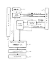
【発明の実施の形態】
以下図面を参照して本発明の第1の実施の形態について説明する。図1はサーマルプリンタ装置のシステム構成を示すブロック図である。図において、11は本サーマルプリンタ装置を統括して制御するコントローラである。このコントローラ11は例えば、マイクロプロセッサにより構成される。
【0019】
12は後述するサーマルヘッドで印字する印字データを記憶している画像メモリである。このサーマルヘッドは1ラインに2560ドットを印字可能なようにそのドット数と同数の発熱素子を列状に配設している。この画像メモリ12には、ビットマップデータとして印字データが記憶されている。
【0020】
この画像メモリ12に記憶されている画像データはコントローラ11の制御により所定のタイミングで読み出されてミクロレジスタ13に格納される。
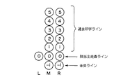
【0021】
このミクロレジスタ13は図2に示すような構成を有する。つまり、該当副走査ラインの印字情報を記憶するMシフトレジスタ、該当副走査ラインに隣接する右ラインの印字情報を記憶するRシフトレジスタ、該当副走査ラインに隣接する左ラインの印字情報を記憶するLシフトレジスタを備えている。
【0022】
M(0)は現在印字している該当主走査ライン上にあるドットの印字データであり、このデータが”1”の場合には発熱素子に通電することを意味し、このデータが”0”の場合には発熱素子に通電しないことを意味する。
【0023】
M(−1)は次に印字する主走査ライン上にあるドットの印字データが記憶される。M(1)は該当主走査ラインの1つ前に印字したラインの印字データ、M(2)はさらに1つ前に印字したラインの印字データ、M(3)はさらに1つ前に印字したラインの印字データ、M(4)はさらに1つ前に印字されたラインの印字データ、M(5)はさらに1つ前に印字されたラインの印字データが記憶される。
【0024】
また、R(−1),R(0)〜R(5)は、前述したM(−1)〜M(5)と同様の印字情報を該当副走査ラインの右に隣接する副走査ラインについて記憶している。
【0025】
さらに、L(−1)〜L(5)は、前述したM(−1)〜M(5)と同様の印字情報を該当副走査ラインの左に隣接する副走査ラインについて記憶している。
【0026】
また、R(−1)〜R(5)に記憶されていた情報は、コントローラ11から出力される所定のタイミング信号によりM(−1)〜M(5)にシフトされる。さらに、M(0)に記憶されていた情報は、コントローラ11から出力される所定のタイミング信号によりL(0)にシフトされる。
【0027】
このミクロレジスタ13のR(−1)〜R(4)の6ビットのミクロ印字情報は履歴メモリ14に出力される。さらに、この履歴メモリ14に記憶されている6ビットのミクロ印字情報はR(0)〜R(5)に記憶される。
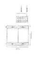
【0028】
履歴メモリ14は1ライン2560ドットに対してそれぞれ6ビットのミクロ印字情報と10ビットのマクロ印字情報を記憶している。つまり、2560×16ビットの記憶容量を有する。この履歴メモリ14のビット1〜5の印字情報は過去5ラインの印字情報である。
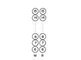
【0029】
また、15はマクロ印字情報を記憶するマクロレジスタである。このマクロレジスタ15は該当副走査ラインの10ビットのマクロ印字情報M(6)〜M(15)の10ビットのマクロ印字情報を記憶するMマクロレジスタ、該当副走査ラインの右に隣接するラインの10ビットのマクロ印字情報R(6)〜R(15)を記憶するRマクロレジスタとから構成されている。
【0030】
また、マクロレジスタ15のマクロ印字情報M(6)〜M(15)は前述した履歴メモリ14のビット6〜15に出力される。
【0031】
履歴メモリ14に記憶されているマクロ印字情報のビット6〜15は、10ビットのアップダウンカウンタ16にラッチされる。このアップダウンカウンタ16にはミクロレジスタ13からミクロ印字情報R(0)〜R(5)が入力されている。さらに、このアップダウンカウンタ16にはコントローラ11から印字速度情報Vが入力されている。
【0032】
アップダウンカウンタ16は、入力された印字速度情報が高速モードのとき、現主走査ラインR(0)が”1”であれば、+1され、R(0)〜R(5)が全て”0”、つまり現走査ラインを含めた過去6ドットすべてが”0”であれば、−1される。
【0033】
一方、アップダウンカウンタ16は、入力された印字速度情報が低速モードのとき、現主走査ラインR(0)が”1”であれば、+1され、R(0)〜R(3)が全て”0”、つまり現走査ラインを含めた過去4ドットがすべて”0”であれば、−1される。
【0034】
そして、このアップダウンカウンタ16で更新されたマクロ印字情報は前述したマクロレジスタM(6)〜M(15)にラッチされる。
【0035】
このように、アップダウンカウンタ16に印字速度情報Vを入力することにより、印字スピードによりサーマルヘッドの冷やし方を変化させている。
【0036】
ミクロレジスタ13のM(−1)〜M(5),L(0),R(0)は熱履歴補正テーブル17の下位アドレス0〜8に、マクロレジスタ15の上位の印字情報M(14),M(15)は、熱履歴補正テーブル17の上位アドレス9,10にそれぞれ入力される。この熱履歴補正テーブル17は4ビットのヘッド通電レベルをヘッドコントローラ18に出力する。
【0037】
熱履歴補正テーブル17は、アドレス11ビット×データ16ビットの構成をしている。つまり、熱履歴補正テーブル17には、マクロ情報M(14),M(15)の2ビットに対応したミクロ補正テーブルが4枚記憶されている。具体的には、マクロ情報M(14),M(15)が”00”であれば、該当ドットの過去の蓄熱が少ないと判断し、ヘッド通電エネルギーレベルの高いミクロ補正テーブルが選択される。また、マクロ情報M(14),M(15)が”01”→”10”→”11”となるにしたがって、該当ドットの蓄熱の程度が多いと判断され、それに伴なったミクロ補正テーブルが選択される。
【0038】
各ミクロ補正テーブルは、隣接ドットを含めた過去の印字パターンに基づいて、ヘッド通電レベル0〜15をヘッドコントローラ18に出力する。つまり、4ビットの通電レベル信号をヘッドコントローラ18に出力する。
【0039】
ヘッドコントローラ18は入力されるヘッド通電レベルに応じた通電時間だけラインサーマルヘッド19を構成する発熱素子に通電する制御を行う。
【0040】
次に、上記のように構成された本発明の第1の実施の形態の動作について説明する。まず、画像メモリ12から読み出された1ビットの画像データは、コントローラ1により所定のタイミングで読み出され、ミクロレジスタ13のR(−1)にラッチされる。このタイミングに同期して、履歴メモリ14から該当ドットM(0)に右側に隣接するRラインの過去の16ビットの印字情報が読み出される。
【0041】
この印字情報のうち、ビット0〜5はミクロレジスタ13のR(0)〜R(5)にラッチされる。
【0042】
この印字情報のうち、ビット6〜15の10ビットのマクロ印字情報は、10ビットのアップダウンカウンタ16にラッチされる。
【0043】
アップダウンカウンタ16は、入力された印字速度情報が高速モードのとき、現主走査ラインR(0)が”1”であれば、+1され、R(0)〜R(5)が全て”0”、つまり現走査ラインを含めた過去6ドットすべてが”0”であれば、−1される。
【0044】
一方、アップダウンカウンタ16は、入力された印字速度情報が低速モードのとき、現主走査ラインR(0)が”1”であれば、+1され、R(0)〜R(3)が全て”0”、つまり現走査ラインを含めた過去4ドットがすべて”0”であれば、−1される。
【0045】
そして、このアップダウンカウンタ16で更新されたマクロ印字情報は前述したマクロレジスタM(6)〜M(15)にラッチされる。
【0046】
このように、アップダウンカウンタ16に印字速度情報Vを入力することにより、印字スピードによりサーマルヘッドの冷やし方を変化させている。
【0047】
また、ミクロレジスタ13のR(−1)〜R(5)及びマクロレジスタ14のR(6)〜R(15)に印字情報がラッチされるタイミングで、それまでR(−1)〜R(15)に格納されていた印字情報は、該当副走査ラインレジスタM(−1)〜M(15)にシフトされる。また、M(0)に入っていた情報は、隣接する左レジスタL(0)にシフトされる。
【0048】
ミクロレジスタ13にラッチされた印字情報R(−1)〜R(4)は、履歴メモリ14のビット0〜5のデータとして、マクロレジスタ15にラッチされた印字情報R(6)〜R(15)は履歴メモリ14のビット6〜15のデータとして所定アドレスに書き込まれる。
【0049】
ミクロレジスタ13のM(−1)〜M(5),L(0),R(0)は熱履歴補正テーブル17の下位アドレス0〜8に、マクロレジスタ15の上位の印字情報M(14),M(15)は、熱履歴補正テーブル17の上位アドレス9,10にそれぞれ入力される。この熱履歴補正テーブル17は4ビットのヘッド通電レベルをヘッドコントローラ18に出力する。
【0050】
マクロ情報M(14),M(15)が”00”であれば、該当ドットの過去の蓄熱が少ないと判断し、ヘッド通電エネルギーレベルの高いミクロ補正テーブルが選択される。また、マクロ情報M(14),M(15)が”01”→”10”→”11”となるにしたがって、該当ドットの蓄熱の程度が多いと判断され、それに伴なったミクロ補正テーブルが選択される。
【0051】
各ミクロ補正テーブルは、隣接ドットを含めた過去の印字パターンに基づいて、ヘッド通電レベル0〜15をヘッドコントローラ18に出力する。つまり、4ビットの通電レベル信号をヘッドコントローラ18に出力する。
【0052】
ヘッドコントローラ18は入力されるヘッド通電レベルに応じた通電時間だけラインサーマルヘッド19を構成する発熱素子に通電する制御を行う。
【0053】
そして、次の画像データが画像メモリ12から送られてくると、以上述べた動作が繰り返し行われ、ラインサーマルヘッド19の発熱素子数分、つまり2560回繰り返すことによって1ラインのデータ変換処理が終了する。
【0054】
そして、熱履歴補正テーブル17から出力された通電レベルは、ヘッドコントローラ18によりラインサーマルヘッド19に転送される。このラインサーマルヘッド19は、所定のラインだけ上記した動作が繰り返され、印刷画像が形成される。
【0055】
このように、過去5ラインの印字情報であるミクロ印字情報及び過去数百ラインのマクロ印字情報の両方に基づいてヘッド通電レベルを決定しているので、べた印字の中の白抜き文字でも良好な印字品質を得ることができる。
【0056】
次に、本発明の第2の実施の形態について図5〜図7を参照して説明する。図5のサーマルプリンタ装置のシステム構成を示す図は、図1のシステム構成図のマクロレジスタ15と熱履歴補正テーブル17との間にマクロ情報を熱履歴補正テーブル17の上位アドレスにアドレス変換部21を設けたものである。
【0057】
つまり、図1においては、マクロレジスタ15の上位2ビットM(14),M(15)が熱履歴補正テーブル17の上位アドレスとして出力されていたが、図5においては、マクロレジスタ15から出力されるM(6)〜M(15)の10ビットのマクロ印字情報を印字モードが高速モードのときと低速モードのときとで切り換えて熱履歴補正テーブル17の2ビットの上位アドレスに変換している。
【0058】
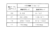
具体的には、高速印字モードでは、マクロ情報が0〜63の場合に熱履歴補正テーブル17の上位アドレスは”00”とされ、マクロ情報が64〜255の場合に熱履歴補正テーブル17の上位アドレスは”01”とされ、マクロ情報が256〜1022の場合に熱履歴補正テーブル17の上位アドレスは”10”とされ、マクロ情報が1023以上の場合に熱履歴補正テーブル17の上位アドレスは”11”とされる。
【0059】
また、低速印字モードでは、マクロ情報が0〜127の場合に熱履歴補正テーブル17の上位アドレスは”00”とされ、マクロ情報が128〜511の場合に熱履歴補正テーブル17の上位アドレスは”01”とされ、マクロ情報が512〜1022の場合に熱履歴補正テーブル17の上位アドレスは”10”とされ、マクロ情報が1023以上の場合に熱履歴補正テーブル17の上位アドレスは”11”とされる。
【0060】
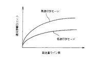
これは、高速印字モードと低速印字モードとでは、サーマルヘッド19が蓄熱していく状態は線形ではなく図7に示すように非線形であるためである。
【0061】
このように、アドレス変換部21を設けることにより、実際のヘッドの蓄熱状態に即して、熱履歴補正テーブル17の上位2ビットのアドレスに変化することができる。つまり、実際のヘッドの蓄熱状態に即したヘッド通電レベルをヘッドコントローラ18に出力することができるので、印字速度が高速モードでも低速モードでも良好な印字品質を保つことができる。
【0062】
なお、上記した第1及び第2の実施の形態において、アップダウンカウンタ16は、高速モードにおいては過去6ドットのすべてが”0”であれば、−1され、
低速モードにおいては過去4ドットのすべてが”0”であれば、−1されていたが、過去すべてが”0”でなくとも所定ドットが”0”であっても良い。
【0063】
なお、上記した第1及び第2の実施の形態において、熱履歴補正テーブル17はROM(リード・オンリ・メモリ)により構成しても良いが、RAM(ランダム・アクセス・メモリ)により構成して、テーブル17の書き換えを可能とするようにしても良い。このように、テーブル17の書き換えを可能とすることにより、印字速度や使用用紙、インクリボン等により、テーブル17の内容を書き替えることにより、より的確な補正結果を得ることができる。
【0064】
さらに、第2の実施の形態において、アドレス変換部21をRAMで構成することにより、印字速度に応じて的確な熱履歴制御を行うことができる。
【0065】
【発明の効果】
以上詳述したように本発明によれば、多くの過去の印字情報をマクロ印字情報として記憶しておき、しかも過去数ラインの微小領域の情報においてもミクロ印字情報としてサーマルヘッドの通電時間に反映されるため、通常の微小文字等の印字品質のみでなく、べた印字の中の白抜き文字等でも印字品質を向上させることができる。さらに、印字速度が高速モードでも低速モードでも良好な印字品質を保つことができる。
【図面の簡単な説明】
【図1】本発明の第1の実施の形態に係わるサーマルプリンタ装置のシステム構成図。
【図2】同実施の形態に係わるミクロレジスタの構成を示す図。
【図3】同実施の形態に係わるマクロレジスタの構成を示す図。
【図4】同実施の形態に係わる履歴メモリの構成を示す図。
【図5】本発明の第2の実施の形態に係わるサーマルプリンタ装置のシステム構成図。
【図6】同実施の形態に係わるアドレス変換部の機能を説明するための図。
【図7】同実施の形態に係わる高速印字モードと低速印字モードでのヘッド蓄熱状態を説明するための図。
【符号の説明】
11…コントローラ、
12…画像メモリ、
13…ミクロレジスタ、
14…履歴メモリ、
15…マクロレジスタ、
16…アップダウンカウンタ、
17…熱履歴補正テーブル、
18…ヘッドコントローラ、
19…サーマルヘッド。
21…熱履歴補正テーブル。[0001]
BACKGROUND OF THE INVENTION
The present invention relates Rusa over Mar printer device can be white text obtaining good print quality.
[0002]
[Prior art]
The thermal printer stores heat when the printing is performed due to the characteristic that printing is performed by heating the thermal head. Due to the thermal storage of the thermal head, black portions may be printed up to a portion where there is no print data, resulting in a problem that print quality is impaired.
[0003]
Conventionally, in order to solve such a problem, the print quality deterioration has been corrected by referring to past print information of the corresponding dot and adjacent dots and controlling the energy for printing of the thermal head. From a macro perspective, the thermal storage state of the thermal head is monitored by a thermistor, and the energy supplied to the thermal head is controlled based on the information.
[0004]
Conventionally, the printing contents printed by a thermal printer have mainly been printing such as characters and barcodes or solid printing. However, in recent years, the actual situation is that there are many kinds of print contents printed by the thermal head. For example, it has been required to form minute white letters in solid prints such as nameplate labels attached to products.
[0005]
[Problems to be solved by the invention]
If the printing speed of the thermal printer is slow, or if the printing content is low, such as characters, the thermal head energy should be controlled based on the past line of printing information.
[0006]
However, when trying to form minute white characters in solid print by high-speed printing of 2 ms / line or more, it is necessary to control the thermal head based on the print information of the past several lines as in the past. The characters were crushed. Further, if the energy supplied to the thermal head is controlled so that the outline characters are not crushed, there is a problem that blurring occurs in a portion to be printed at the start of printing.
[0007]
Therefore, when trying to control the energy supplied to the thermal head based on a lot of past printing information, there is a problem that a large amount of memory is required and the hardware becomes large-scale.
[0008]
In addition, in the method of reflecting the information of the head thermistor on the printing energy, when printing is performed at a high speed of 2 ms / line or more, the printout of the white character is generated before the thermistor reacts, and the ink ribbon is heated. Problems occur.
[0009]
The present invention has been made in view of the above, and its object is to provide a salicylate over circle printer also possible to obtain a good printing quality with white text in the solid printing.
[0011]
[Means for Solving the Problems]
According to the first aspect of the present invention, in a thermal printer that energizes a line thermal head in which a plurality of heating elements are arranged, and melts or sublimates ink ribbon ink on a sheet by heat generated by the energization, the past includes adjacent elements. A history memory for storing micro print information of several lines and macro print information of past several hundred lines or more of the corresponding element, and micro print information and macro print information read from the history memory are input, and the thermal head is energized. A thermal history correction table that outputs an energization level indicating time, and a head control unit that controls an energization time of a corresponding element of the thermal head according to the energization level output from the thermal history correction table. history correction table, based on past printing pattern including adjacent dots to output the energization level Having a plurality of micro-print information correction table, the macro print information, characterized in that one of the plurality of micro-print information correction table is selected.
[0012]
According to a second aspect of the invention, the macro print information according to
[0013]
According to a third aspect of the invention, up-down counter according to
[0015]
The invention described in
[0017]
The invention according to
[0018]
DETAILED DESCRIPTION OF THE INVENTION
Hereinafter, a first embodiment of the present invention will be described with reference to the drawings. FIG. 1 is a block diagram showing the system configuration of the thermal printer apparatus. In the figure,
[0019]
An
[0020]
The image data stored in the
[0021]
The
[0022]
M (0) is the print data of the dot on the main scanning line currently printed. If this data is “1”, it means that the heating element is energized, and this data is “0”. In this case, it means that the heating element is not energized.
[0023]
M (-1) stores print data of dots on the main scanning line to be printed next. M (1) is the print data of the line printed immediately before the corresponding main scanning line, M (2) is the print data of the line printed one more time before, and M (3) is printed one more time before. Line print data, M (4) stores the print data of the line printed one more time before, and M (5) stores the print data of the line printed one more time before.
[0024]
In addition, R (-1) and R (0) to R (5) indicate the same print information as M (-1) to M (5) described above for the sub-scanning line adjacent to the right of the corresponding sub-scanning line. I remember it.
[0025]
Further, L (−1) to L (5) store the same print information as M (−1) to M (5) described above for the sub scanning line adjacent to the left of the corresponding sub scanning line.
[0026]
Further, the information stored in R (−1) to R (5) is shifted to M (−1) to M (5) by a predetermined timing signal output from the
[0027]
The 6-bit micro print information of R (−1) to R (4) of the
[0028]
The
[0029]
A
[0030]
Further, the macro print information M (6) to M (15) of the
[0031]
Bits 6 to 15 of the macro print information stored in the
[0032]
The up / down
[0033]
On the other hand, when the input printing speed information is in the low speed mode, the up / down
[0034]
The macro print information updated by the up / down
[0035]
In this way, by inputting the printing speed information V to the up / down
[0036]
M micro register 13 (-1) ~M (5) , L (0), R (0) to the lower address 0-8 of the thermal history correction table 17, the print information of the upper McHenry Rorejisuta 15 M (14) , M (15) are input to the
[0037]
The thermal history correction table 17 has an address of 11 bits × data of 16 bits. That is, four micro correction tables corresponding to 2 bits of the macro information M (14) and M (15) are stored in the thermal history correction table 17. Specifically, if the macro information M (14), M (15) is “00”, it is determined that the past dot has little heat storage, and a micro correction table having a high head energization energy level is selected. Further, as the macro information M (14), M (15) is changed from “01” → “10” → “11”, it is determined that the degree of heat storage of the corresponding dot is large, and the micro correction table associated therewith is determined. Selected.
[0038]
Each micro correction table outputs head
[0039]
The head controller 18 performs control to energize the heating elements constituting the line thermal head 19 for the energization time corresponding to the input head energization level.
[0040]
Next, the operation of the first embodiment of the present invention configured as described above will be described. First, image data of 1 bit read from the
[0041]
Of this print information,
[0042]
Among the print information, 10-bit macro print information of bits 6 to 15 is latched by the 10-bit up / down
[0043]
The up / down
[0044]
On the other hand, when the input printing speed information is in the low speed mode, the up / down
[0045]
The macro print information updated by the up / down
[0046]
In this way, by inputting the printing speed information V to the up / down
[0047]
At the timing when the print information is latched in R (-1) to R (5) of the
[0048]
The print information R (-1) to R (4) latched in the
[0049]
M micro register 13 (-1) ~M (5) , L (0), R (0) to the lower address 0-8 of the thermal history correction table 17, the print information of the upper McHenry Rorejisuta 15 M (14) , M (15) are input to the
[0050]
If the macro information M (14), M (15) is “00”, it is determined that the past heat storage of the corresponding dot is small, and a micro correction table having a high head energization energy level is selected. Further, as the macro information M (14), M (15) is changed from “01” → “10” → “11”, it is determined that the degree of heat storage of the corresponding dot is large, and the micro correction table associated therewith is determined. Selected.
[0051]
Each micro correction table outputs head
[0052]
The head controller 18 performs control to energize the heating elements constituting the line thermal head 19 for the energization time corresponding to the input head energization level.
[0053]
When the next image data is sent from the
[0054]
The energization level output from the thermal history correction table 17 is transferred to the line thermal head 19 by the head controller 18. The line thermal head 19 repeats the above-described operation for a predetermined line to form a printed image.
[0055]
As described above, since the head energization level is determined based on both the micro print information which is the print information of the past five lines and the macro print information of the past several hundred lines, the white characters in the solid print are also good. Print quality can be obtained.
[0056]
Next, a second embodiment of the present invention will be described with reference to FIGS. Figure to higher addresses converter 21 of the thermal history correction table 17 macro information between the
[0057]
That is, in FIG. 1, the upper 2 bits M McHenry Rorejisuta 15 (14), but M (15) has been output as the upper address of the thermal history correction table 17, in Figure 5, is output from the macro Rorejisuta 15 M (6) to M (15) 10-bit macro print information is switched between when the print mode is the high-speed mode and when the print mode is the low-speed mode, and converted into the 2-bit upper address of the thermal history correction table 17 .
[0058]
Specifically, in the high-speed printing mode, when the macro information is 0 to 63, the upper address of the thermal history correction table 17 is “00”, and when the macro information is 64 to 255, the upper address of the thermal history correction table 17 is set. When the macro information is 256 to 1022, the upper address of the thermal history correction table 17 is “10”, and when the macro information is 1023 or more, the upper address of the thermal history correction table 17 is “01”. 11 ".
[0059]
In the low-speed printing mode, when the macro information is 0 to 127, the upper address of the thermal history correction table 17 is “00”, and when the macro information is 128 to 511, the upper address of the thermal history correction table 17 is “ When the macro information is 512 to 1022, the upper address of the thermal history correction table 17 is “10”, and when the macro information is 1023 or more, the upper address of the thermal history correction table 17 is “11”. Is done.
[0060]
This is because in the high-speed printing mode and the low-speed printing mode, the state in which the thermal head 19 stores heat is not linear but nonlinear as shown in FIG.
[0061]
Thus, by providing the address converter 21 can be in line with the heat storage state of the actual head, it changes the upper two bits of the add-less thermal history correction table 17. That is, since the head energization level corresponding to the actual heat storage state of the head can be output to the head controller 18, good print quality can be maintained regardless of whether the print speed is the high speed mode or the low speed mode.
[0062]
In the first and second embodiments described above, the up / down
In the low-speed mode, if all of the past four dots are “0”, it is set to −1. However, the predetermined dot may be “0” even if all the past are not “0”.
[0063]
In the first and second embodiments described above, the thermal history correction table 17 may be composed of ROM (read only memory), but is composed of RAM (random access memory). The table 17 may be rewritten. Thus, by making the table 17 rewritable, a more accurate correction result can be obtained by rewriting the contents of the table 17 with the printing speed, paper used, ink ribbon, or the like.
[0064]
Furthermore, in the second embodiment, by configuring the address conversion unit 21 with a RAM, accurate thermal history control can be performed according to the printing speed.
[0065]
【The invention's effect】
As described above in detail, according to the present invention, a large amount of past print information is stored as macro print information, and the information on the micro area of the past several lines is reflected in the energization time of the thermal head as micro print information. Therefore, the print quality can be improved not only for the normal print quality of minute characters but also for the white characters in the solid print. Furthermore, good print quality can be maintained regardless of whether the print speed is the high speed mode or the low speed mode.
[Brief description of the drawings]
FIG. 1 is a system configuration diagram of a thermal printer apparatus according to a first embodiment of the present invention.
FIG. 2 is a diagram showing a configuration of a micro register according to the embodiment.
FIG. 3 is a view showing a configuration of a macro register according to the embodiment;
FIG. 4 is a diagram showing a configuration of a history memory according to the embodiment.
FIG. 5 is a system configuration diagram of a thermal printer apparatus according to a second embodiment of the present invention.
FIG. 6 is a diagram for explaining a function of an address conversion unit according to the embodiment;
FIG. 7 is a view for explaining a head heat storage state in a high-speed printing mode and a low-speed printing mode according to the embodiment.
[Explanation of symbols]
11 ... Controller,
12 ... Image memory,
13 ... Micro register,
14 ... history memory,
15: Macro register,
16: Up / down counter,
17 ... heat history correction table,
18 ... Head controller,
19 ... Thermal head.
21 ... Thermal history correction table.
Claims (5)
隣接素子も含めた過去数ラインのミクロ印字情報及び該当素子の過去数百ライン以上のマクロ印字情報を記憶する履歴メモリと、
この履歴メモリから読み出されたミクロ印字情報及びマクロ印字情報を入力し、上記サーマルヘッドの通電時間を示す通電レベルを出力する熱履歴補正テーブルと、
この熱履歴補正テーブルから出力される通電レベルに応じて上記サーマルヘッドの該当素子の通電時間を制御するヘッド制御部とを具備し、
上記熱履歴補正テーブルは、隣接ドットを含めた過去の印字パターンに基づいて上記通電レベルを出力するミクロ印字情報補正テーブルを複数持ち、マクロ印字情報により上記複数のミクロ印字情報補正テーブルのうちの一つが選択されることを特徴とするサーマルプリンタ装置。In a thermal printer that energizes a line thermal head in which a plurality of heating elements are arranged, and melts or sublimates ink ribbon ink on paper by the heat generated by the energization,
A history memory that stores micro print information of past several lines including adjacent elements and macro print information of past hundreds of lines of the corresponding element;
A thermal history correction table for inputting the micro print information and the macro print information read from the history memory and outputting an energization level indicating the energization time of the thermal head;
A head control unit that controls the energization time of the corresponding element of the thermal head according to the energization level output from the thermal history correction table;
The thermal history correction table has a plurality of micro print information correction tables for outputting the energization level based on past print patterns including adjacent dots, and one of the plurality of micro print information correction tables based on the macro print information. A thermal printer device characterized in that one is selected.
Priority Applications (1)
| Application Number | Priority Date | Filing Date | Title |
|---|---|---|---|
| JP28294399A JP3661985B2 (en) | 1999-10-04 | 1999-10-04 | Thermal printer device |
Applications Claiming Priority (1)
| Application Number | Priority Date | Filing Date | Title |
|---|---|---|---|
| JP28294399A JP3661985B2 (en) | 1999-10-04 | 1999-10-04 | Thermal printer device |
Publications (2)
| Publication Number | Publication Date |
|---|---|
| JP2001096779A JP2001096779A (en) | 2001-04-10 |
| JP3661985B2 true JP3661985B2 (en) | 2005-06-22 |
Family
ID=17659133
Family Applications (1)
| Application Number | Title | Priority Date | Filing Date |
|---|---|---|---|
| JP28294399A Expired - Lifetime JP3661985B2 (en) | 1999-10-04 | 1999-10-04 | Thermal printer device |
Country Status (1)
| Country | Link |
|---|---|
| JP (1) | JP3661985B2 (en) |
Families Citing this family (1)
| Publication number | Priority date | Publication date | Assignee | Title |
|---|---|---|---|---|
| JP2014008771A (en) * | 2012-07-03 | 2014-01-20 | Toshiba Tec Corp | Thermal printer and program therefor |
-
1999
- 1999-10-04 JP JP28294399A patent/JP3661985B2/en not_active Expired - Lifetime
Also Published As
| Publication number | Publication date |
|---|---|
| JP2001096779A (en) | 2001-04-10 |
Similar Documents
| Publication | Publication Date | Title |
|---|---|---|
| US4777536A (en) | Thermal printing device | |
| US4816843A (en) | Method of controlling a thermal head | |
| JP3661985B2 (en) | Thermal printer device | |
| US5382965A (en) | Wax transfer type thermal printing method and thermal printer | |
| JPS6268367A (en) | Thermosensitive recorder | |
| EP0903931B1 (en) | Thermal recording apparatus | |
| JP3020732B2 (en) | Thermal printing method and thermal printer | |
| JPH0332262B2 (en) | ||
| JP2854329B2 (en) | Image recording method and apparatus | |
| US5103245A (en) | Recording apparatus having heat-generating elements driven in view of past recording | |
| JP2899050B2 (en) | Thermal transfer recording device | |
| JPH0616764Y2 (en) | Dot matrix printer | |
| JP2570363B2 (en) | How to energize the thermal head in a thermal printer | |
| JP2002292918A (en) | Method for checking appropriate tone of thermal printer | |
| JPH04220358A (en) | Thermal printer | |
| JPH08132674A (en) | Print controlling method | |
| JPH06143649A (en) | Signal processing circuit for thermal transfer printer | |
| JPH06255159A (en) | Image recording method and its apparatus | |
| JPH04339668A (en) | Line thermal printer | |
| JPH11309894A (en) | Printer | |
| JP3852201B2 (en) | Thermal recording device | |
| JPS63252751A (en) | Printing control apparatus | |
| JPH0790648B2 (en) | Thermal transfer printer | |
| JPS5833481A (en) | Printing system of thermal printer | |
| JPH1016265A (en) | Printer |
Legal Events
| Date | Code | Title | Description |
|---|---|---|---|
| A977 | Report on retrieval |
Free format text: JAPANESE INTERMEDIATE CODE: A971007 Effective date: 20041201 |
|
| A131 | Notification of reasons for refusal |
Free format text: JAPANESE INTERMEDIATE CODE: A131 Effective date: 20041207 |
|
| A521 | Written amendment |
Free format text: JAPANESE INTERMEDIATE CODE: A523 Effective date: 20050204 |
|
| TRDD | Decision of grant or rejection written | ||
| A01 | Written decision to grant a patent or to grant a registration (utility model) |
Free format text: JAPANESE INTERMEDIATE CODE: A01 Effective date: 20050315 |
|
| A61 | First payment of annual fees (during grant procedure) |
Free format text: JAPANESE INTERMEDIATE CODE: A61 Effective date: 20050318 |
|
| R150 | Certificate of patent or registration of utility model |
Ref document number: 3661985 Country of ref document: JP Free format text: JAPANESE INTERMEDIATE CODE: R150 Free format text: JAPANESE INTERMEDIATE CODE: R150 |
|
| FPAY | Renewal fee payment (event date is renewal date of database) |
Free format text: PAYMENT UNTIL: 20080401 Year of fee payment: 3 |
|
| FPAY | Renewal fee payment (event date is renewal date of database) |
Free format text: PAYMENT UNTIL: 20090401 Year of fee payment: 4 |
|
| FPAY | Renewal fee payment (event date is renewal date of database) |
Free format text: PAYMENT UNTIL: 20100401 Year of fee payment: 5 |
|
| FPAY | Renewal fee payment (event date is renewal date of database) |
Free format text: PAYMENT UNTIL: 20100401 Year of fee payment: 5 |
|
| FPAY | Renewal fee payment (event date is renewal date of database) |
Free format text: PAYMENT UNTIL: 20110401 Year of fee payment: 6 |
|
| FPAY | Renewal fee payment (event date is renewal date of database) |
Free format text: PAYMENT UNTIL: 20120401 Year of fee payment: 7 |
|
| FPAY | Renewal fee payment (event date is renewal date of database) |
Free format text: PAYMENT UNTIL: 20130401 Year of fee payment: 8 |
|
| FPAY | Renewal fee payment (event date is renewal date of database) |
Free format text: PAYMENT UNTIL: 20130401 Year of fee payment: 8 |
|
| FPAY | Renewal fee payment (event date is renewal date of database) |
Free format text: PAYMENT UNTIL: 20140401 Year of fee payment: 9 |
|
| EXPY | Cancellation because of completion of term |