JP3660977B2 - Two-way orifice check valve device for hydraulic circuit - Google Patents
Two-way orifice check valve device for hydraulic circuit Download PDFInfo
- Publication number
- JP3660977B2 JP3660977B2 JP2002358193A JP2002358193A JP3660977B2 JP 3660977 B2 JP3660977 B2 JP 3660977B2 JP 2002358193 A JP2002358193 A JP 2002358193A JP 2002358193 A JP2002358193 A JP 2002358193A JP 3660977 B2 JP3660977 B2 JP 3660977B2
- Authority
- JP
- Japan
- Prior art keywords
- pressure chamber
- orifice
- hydraulic circuit
- pressure
- check valve
- Prior art date
- Legal status (The legal status is an assumption and is not a legal conclusion. Google has not performed a legal analysis and makes no representation as to the accuracy of the status listed.)
- Expired - Fee Related
Links
Images


Classifications
-
- F—MECHANICAL ENGINEERING; LIGHTING; HEATING; WEAPONS; BLASTING
- F16—ENGINEERING ELEMENTS AND UNITS; GENERAL MEASURES FOR PRODUCING AND MAINTAINING EFFECTIVE FUNCTIONING OF MACHINES OR INSTALLATIONS; THERMAL INSULATION IN GENERAL
- F16K—VALVES; TAPS; COCKS; ACTUATING-FLOATS; DEVICES FOR VENTING OR AERATING
- F16K15/00—Check valves
-
- F—MECHANICAL ENGINEERING; LIGHTING; HEATING; WEAPONS; BLASTING
- F16—ENGINEERING ELEMENTS AND UNITS; GENERAL MEASURES FOR PRODUCING AND MAINTAINING EFFECTIVE FUNCTIONING OF MACHINES OR INSTALLATIONS; THERMAL INSULATION IN GENERAL
- F16K—VALVES; TAPS; COCKS; ACTUATING-FLOATS; DEVICES FOR VENTING OR AERATING
- F16K17/00—Safety valves; Equalising valves, e.g. pressure relief valves
- F16K17/02—Safety valves; Equalising valves, e.g. pressure relief valves opening on surplus pressure on one side; closing on insufficient pressure on one side
- F16K17/04—Safety valves; Equalising valves, e.g. pressure relief valves opening on surplus pressure on one side; closing on insufficient pressure on one side spring-loaded
- F16K17/08—Safety valves; Equalising valves, e.g. pressure relief valves opening on surplus pressure on one side; closing on insufficient pressure on one side spring-loaded with special arrangements for providing a large discharge passage
-
- F—MECHANICAL ENGINEERING; LIGHTING; HEATING; WEAPONS; BLASTING
- F16—ENGINEERING ELEMENTS AND UNITS; GENERAL MEASURES FOR PRODUCING AND MAINTAINING EFFECTIVE FUNCTIONING OF MACHINES OR INSTALLATIONS; THERMAL INSULATION IN GENERAL
- F16K—VALVES; TAPS; COCKS; ACTUATING-FLOATS; DEVICES FOR VENTING OR AERATING
- F16K15/00—Check valves
- F16K15/02—Check valves with guided rigid valve members
- F16K15/04—Check valves with guided rigid valve members shaped as balls
-
- F—MECHANICAL ENGINEERING; LIGHTING; HEATING; WEAPONS; BLASTING
- F16—ENGINEERING ELEMENTS AND UNITS; GENERAL MEASURES FOR PRODUCING AND MAINTAINING EFFECTIVE FUNCTIONING OF MACHINES OR INSTALLATIONS; THERMAL INSULATION IN GENERAL
- F16K—VALVES; TAPS; COCKS; ACTUATING-FLOATS; DEVICES FOR VENTING OR AERATING
- F16K17/00—Safety valves; Equalising valves, e.g. pressure relief valves
- F16K17/02—Safety valves; Equalising valves, e.g. pressure relief valves opening on surplus pressure on one side; closing on insufficient pressure on one side
- F16K17/04—Safety valves; Equalising valves, e.g. pressure relief valves opening on surplus pressure on one side; closing on insufficient pressure on one side spring-loaded
- F16K17/10—Safety valves; Equalising valves, e.g. pressure relief valves opening on surplus pressure on one side; closing on insufficient pressure on one side spring-loaded with auxiliary valve for fluid operation of the main valve
-
- Y—GENERAL TAGGING OF NEW TECHNOLOGICAL DEVELOPMENTS; GENERAL TAGGING OF CROSS-SECTIONAL TECHNOLOGIES SPANNING OVER SEVERAL SECTIONS OF THE IPC; TECHNICAL SUBJECTS COVERED BY FORMER USPC CROSS-REFERENCE ART COLLECTIONS [XRACs] AND DIGESTS
- Y10—TECHNICAL SUBJECTS COVERED BY FORMER USPC
- Y10T—TECHNICAL SUBJECTS COVERED BY FORMER US CLASSIFICATION
- Y10T137/00—Fluid handling
- Y10T137/7722—Line condition change responsive valves
- Y10T137/7771—Bi-directional flow valves
-
- Y—GENERAL TAGGING OF NEW TECHNOLOGICAL DEVELOPMENTS; GENERAL TAGGING OF CROSS-SECTIONAL TECHNOLOGIES SPANNING OVER SEVERAL SECTIONS OF THE IPC; TECHNICAL SUBJECTS COVERED BY FORMER USPC CROSS-REFERENCE ART COLLECTIONS [XRACs] AND DIGESTS
- Y10—TECHNICAL SUBJECTS COVERED BY FORMER USPC
- Y10T—TECHNICAL SUBJECTS COVERED BY FORMER US CLASSIFICATION
- Y10T137/00—Fluid handling
- Y10T137/7722—Line condition change responsive valves
- Y10T137/7837—Direct response valves [i.e., check valve type]
- Y10T137/7847—With leak passage
-
- Y—GENERAL TAGGING OF NEW TECHNOLOGICAL DEVELOPMENTS; GENERAL TAGGING OF CROSS-SECTIONAL TECHNOLOGIES SPANNING OVER SEVERAL SECTIONS OF THE IPC; TECHNICAL SUBJECTS COVERED BY FORMER USPC CROSS-REFERENCE ART COLLECTIONS [XRACs] AND DIGESTS
- Y10—TECHNICAL SUBJECTS COVERED BY FORMER USPC
- Y10T—TECHNICAL SUBJECTS COVERED BY FORMER US CLASSIFICATION
- Y10T137/00—Fluid handling
- Y10T137/8593—Systems
- Y10T137/87917—Flow path with serial valves and/or closures
Landscapes
- Engineering & Computer Science (AREA)
- General Engineering & Computer Science (AREA)
- Mechanical Engineering (AREA)
- Hydraulic Clutches, Magnetic Clutches, Fluid Clutches, And Fluid Joints (AREA)
- Check Valves (AREA)
- Control Of Transmission Device (AREA)
- Safety Valves (AREA)
- Fluid-Pressure Circuits (AREA)
Description
【0001】
【発明の属する技術分野】
本発明は、油圧回路用ツーウェイオリフィスチェックバルブ装置に関し、より詳しくは、クラッチと同じ摩擦要素の作動を制御する油圧回路にあって、クラッチの締結、及び解放時の制御圧を安定させるための油圧回路の構成を単純化する油圧回路用ツーウェイオリフィスチェックバルブ装置に関する。
【0002】
【従来の技術】
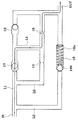
一般に、油圧を利用してクラッチと同じ摩擦要素の作動を制御する油圧回路は、摩擦要素の急激な締結を防止するための要素を備えているが、それは、図1に示すように、制御圧が流入する流入管路(IN)から制御圧が摩擦要素へ供給される流出管路(OUT)の間の2つのチェックバルブ10、12と2つのオリフィス14、16、及び1つの圧力バルブ18とから構成されている。
【0003】
即ち、流入管路(IN)からチェックバルブ10、12が位置する第1管路(L1)と、圧力バルブ18が位置する第2管路(L2)とがそれぞれ分岐して、第1管路(L1)からはオリフィス14、16が位置する第3管路(L3)が分岐し、第1管路(L1)と第2管路(L2)及び第3管路(L3)はそれぞれ流出管路(OUT)で1つに合流する。
【0004】
さらに、第1管路(L1)と第3管路(L3)との間には2つの管路を流通可能にする第4管路(L4)が配設されている。
そして、第1チェックバルブ10と第2チェックバルブ12は第1管路L1上に相互反対方向に配置される。
さらに、第1オリフィス14と第2オリフィスは第3管路L3上に離隔して順次配置される。
【0005】
一方、圧力バルブ18は、第2管路(L2)上に配置され、背面がリターンスプリング18aを介して弾発支持される金属球18bを備えた構造を有する。
上記のように構成される摩擦要素の作動を制御する油圧回路で、制御圧を媒介にクラッチと同様の該当摩擦要素を締結する場合には、図1に示すように、油圧回路の流入管路(IN)を通じて流入する制御圧が第1管路(L1)上の第1チェックバルブ10を通り第4管路(L4)へ流入し、その第4管路(L4)へ流入した制御圧は第2オリフィス16を経て油圧回路の流出管路(OUT)を通って該当摩擦要素に供給される。
【0006】
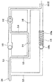
そして、クラッチと同様の該当摩擦要素を解放する場合には、図2に示すように、油圧回路の流出管路(OUT)を通って流入した制御圧が第1管路(L1)上の第2チェックバルブ12を通り再び第4管路(L4)を通って第3管路(L3)へ流入し、その第3管路(L3)へ流入した制御圧は第1オリフィス14を通り再び第1管路(L1)を通って流入管路(IN)へ排出される。
【0007】
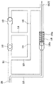
さらに、上記の構成を有する油圧回路に大きな制御圧が作用してクラッチと同様の該当摩擦要素を迅速に締結させる場合には、図3に示したように、流入管路(IN)へ流入した制御圧が第2管路(L2)へ流入して、その第2管路(L2)へ流入した制御圧は圧力バルブ18を通り流出管路(OUT)を通って該当摩擦要素に迅速に供給される。
この時、圧力バルブ18は、大きな制御圧によって金属球18bがリターンスプリング18aを収縮する。
【0008】
しかし、上記のような油圧回路には、2つのチェックバルブ10、12と2つのオリフィス14、16及び1つの圧力バルブ18をそれぞれ個別に設けるための3つの管路(L1、L2、L3)と、この内2つの管路の間を連結する1つの管路(L4)をそれぞれ備える必要があるため、油圧回路が複雑となるほか、それを製造するにも多くの費用がかかるという短所がある。
【先行技術文献】
【特許文献1】
特開平7−323994
【特許文献2】
特開2000−062488
【0009】
【発明が解決しようとする課題】
本発明の目的は、摩擦要素の締結、及び解放をそれぞれ制御する油圧回路の構成を単純化し、摩擦要素の締結、及び解放時の正常な機能が確保できると共に、製造費用が低減できる油圧回路用ツーウェイオリフィスチェックバルブ装置を提供することにある。
【0010】
【課題を解決するための手段】
上記目的を達成するため本発明は、流入管路上に形成された第1圧力室内に移動が可能に設けられた本体部と、該本体部の両端にそれぞれ形成された第1オリフィスと第2オリフィス、前記第1オリフィスと前記第2オリフィスとの間を連通する交通通路、前記本体部の外周面と前記第1圧力室との間に流動通路を形成するように前記本体部に形成された複数個の突出部及び前記突出部との間に前記交通通路と連通する貫通通路とを備えるオリフィスチェックバルブと、前記第1圧力室と接する位置に流出管路と連通するように形成された第2圧力室と、前記第2圧力室内で背面がリターンスプリングを介して弾発支持されると共に内部に流動通路を備えたバルブ体とからなる圧力バルブと、を含んで構成することを特徴とする
【0011】
【発明の実施の形態】
以下、本発明の実施例を添付図によって詳述する。
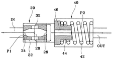
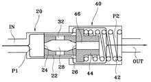
図4は、本発明によるツーウェイオリフィスチェックバルブを備えた油圧回路の構成図であり、制御圧が流入する流入管路(IN)から制御圧が摩擦要素へ供給される流出管路(OUT)との間に、制御圧の変動を減らすと共に制御圧の作用方向を決定するオリフィスとチェックバルブの役割を同時にするオリフィスチェックバルブ20と、急激な制御圧の流入時にそれを通過させて該当摩擦要素の急速な締結を可能にする圧力バルブ40を一体化して備えている。
【0012】
ここで、オリフィスチェックバルブ20は図4または図5にそれぞれ示したように、流入管路(IN)上に形成された第1圧力室(P1)内で移動が可能に形成されたシリンダ形状の本体部22と、その本体部22の前/後段にそれぞれ形成された第1オリフィス24と第2オリフィス26、本体部22の内部の第1オリフィス24と第2オリフィス26との間を流通可能にする通路28、本体部22の外周面に放射状に突出して第1圧力室(P1)との間に複数個の流動通路を形成する複数個の突出部30及び、その突出部30の間に本体部22を貫通して交通通路28と連通する貫通通路32を備える。
【0013】
そして、圧力バルブ40は第1圧力室(P1)と接する部位に形成された第2圧力室(P2)内で背面がリターンスプリング42を介して弾発支持されるバルブ体44からなるが、そのバルブ44には中央に貫通した流動通路46を形成している。
さらに、第1圧力室(P1)の断面積は第2圧力室(P2)の断面積より小さく形成され、オリフィスチェックバルブ20の本体部22の断面積も圧力バルブ40のバルブ44の断面積より小さく形成されている。
【0014】
これによって、第1圧力室(P1)内に移動可能に設けられた本体部22は第2圧力室(P2)内へ流入できると共に、第2圧力室(P2)内にリターンスプリング42を介して弾発支持されたバルブ体44を加圧できるようになっている。
また、圧力バルブ40のバルブ体44の断面積は第2圧力室(P2)の断面積より小さく形成されている。
これによって、第2圧力室(P2)内でバルブ体44の外周面と第2圧力室(P2)との間の空間へ制御圧の移動が可能になる。
【0015】
次に、本発明の作動について述べる。
先に、摩擦要素の作動を制御する油圧回路で制御圧を媒介にクラッチと同様の該当摩擦要素を締結する場合には、図6に示したように、油圧回路の流入管路(IN)を通って第1圧力室(P1)内に流入した制御圧が本体部22の外周面に形成された突出部30の間と第1圧力室(P1)の内周面の間の空間を通って貫通通路32を経て本体部22内へ流入し、その本体部22内に流入した制御圧は第2オリフィス26を通り第2圧力室(P2)へ流入する。その第2圧力室(P2)内へ流入した制御圧は圧力バルブ40のバルブ体44に中央から形成された流動通路46を通り油圧回路の流出管路(OUT)を通じて該当摩擦要素に供給される。
【0016】
この時、第1圧力室(P1)内本体部22は制御圧によって右側に押されバルブ体44に接するようになり、そのバルブ体44は背面がリターンスプリング42を介して弾発支持されており、そのバルブ体44の移動を阻止する。
そして、クラッチと同様の該当摩擦要素を解放する場合には、図7に示したように、油圧回路の流出管路(OUT)を通って第2圧力室(P2)へ流入した制御圧がバルブ体44の中央に形成された流動通路46を通り第1圧力室(P1)内へ流入する。その第1圧力室(P1)内へ流入した制御圧は本体部22の外周面に形成された突出部30間の溝部と第1圧力室P1の内周面の間を通り、貫通路32を経て本体部22内へ流入し、その本体部22内に流入した制御圧は第1オリフィス24を通り油圧回路の流入管路(IN)へ排出される。
【0017】
この時、第1圧力室(P1)内の本体部22は制御圧によって左側へ押され、第2圧力室(P2)内のバルブ体44は第1圧力室(P1)と第2圧力室(P2)との間の断面積の差によって第1圧力室(P1)内に流入できないようになる。
【0018】
さらに、上記油圧回路に大きい制御圧が作用してクラッチと同様の該当摩擦要素を迅速に締結させる場合には、図8に示すように、流入管路(IN)を通って第1圧力室(P1)内に流入した制御圧が本体部22の外周面に形成された突出部30の間の溝部を通り第2圧力室(P2)へ直接流入する。この第2圧力室(P2)へ流入する制御圧はバルブ体44と第2圧力室P2の外周面との間の空間を通じて流出管路(OUT)を経て該当摩擦要素に迅速に供給される。
【0019】
この時、第1圧力室(P1)内の本体部22は、大きい制御圧によって一部が第2圧力室(P2)の内部に向って右側に押され背面がリターンスプリング42を介して弾発支持されたバルブ体44を右側に押すが、それによって、本体部22と第1圧力室(P1)の間の空間と、バルブ体44と第2圧力室(P2)との間の空間が相互に開通状態になる。
【0020】
【発明の効果】
本発明により、クラッチと同様の摩擦要素の締結、及び解放をそれぞれ制御すると共に制御圧の変動時にそれを吸収して摩擦要素の締結時のショックを防止する油圧回路の構成を、単一の管路上に順次配置してオリフィスとチェックバルブの役割を同時にするオリフィスチェックバルブ20と、急激な制御圧の流入時にそれを通過させて該当摩擦要素の急速な締結を可能にする圧力バルブ40とから構成することによって、構造の単純化を図り油圧回路が占める容積を減らし、製造にかかる費用も減らすことができる。
【図面の簡単な説明】
【図1】従来のクラッチ締結、及び解除のための制御用油圧回路であり、クラッチの締結時の制御圧の経路を示した状態図である。
【図2】図1に示した油圧回路でクラッチ解放時の制御圧経路を示した状態図である。
【図3】図1に示した油圧回路でクラッチの締結時の高い制御圧の経路を示した状態図である。
【図4】本発明によるツーウェイオリフィスチェックバルブを備えた油圧回路の構成を示した図面である。
【図5】図4に示したオリフィスチェックバルブを示した斜視図である。
【図6】図5に示した油圧回路でクラッチ締結時の制御圧経路を示した状態図である。
【図7】図5に示した油圧回路でクラッチ解放時の制御圧経路を示した状態図である。
【図8】図5に示した油圧回路でクラッチの締結時の高い制御圧の経路を示した状態図である。
【符号の説明】
20 オリフィスチェックバルブ
22 本体部
24 第1オリフィス
26 第2オリフィス
28 交通通路
30 突出部
32 貫通通路
40 圧力バルブ
42 リターンスプリング
44 バルブ体
46 流動通路[0001]
BACKGROUND OF THE INVENTION
The present invention relates to a two-way orifice check valve device for a hydraulic circuit, and more particularly to a hydraulic circuit that controls the operation of the same friction element as a clutch, and a hydraulic pressure for stabilizing the control pressure when the clutch is engaged and released. The present invention relates to a two-way orifice check valve device for a hydraulic circuit that simplifies the circuit configuration.
[0002]
[Prior art]
In general, a hydraulic circuit that uses hydraulic pressure to control the operation of the same friction element as a clutch includes an element for preventing sudden engagement of the friction element, as shown in FIG. Two
[0003]
That is, the first pipe line (L1) where the
[0004]
Furthermore, the 4th pipe line (L4) which can distribute | circulate two pipe lines is arrange | positioned between the 1st pipe line (L1) and the 3rd pipe line (L3).
The
Further, the
[0005]
On the other hand, the
In the hydraulic circuit for controlling the operation of the friction element configured as described above, in the case where the corresponding friction element similar to the clutch is engaged through the control pressure, as shown in FIG. The control pressure flowing in through (IN) flows into the fourth pipe (L4) through the
[0006]
When the corresponding friction element similar to the clutch is released, as shown in FIG. 2, the control pressure that has flowed in through the outflow line (OUT) of the hydraulic circuit is changed to the first level on the first line (L1). 2 After passing through the
[0007]
Further, when a large control pressure acts on the hydraulic circuit having the above-described configuration and the corresponding friction element similar to the clutch is quickly engaged, as shown in FIG. 3, the fluid flows into the inflow conduit (IN). The control pressure flows into the second pipe (L2), and the control pressure that flows into the second pipe (L2) passes through the
At this time, in the
[0008]
However, in the hydraulic circuit as described above, there are three pipe lines (L1, L2, L3) for individually providing two
[Prior art documents]
[Patent Document 1]
JP-A-7-323994
[Patent Document 2]
JP2000-062488
[0009]
[Problems to be solved by the invention]
An object of the present invention is for a hydraulic circuit that simplifies the configuration of a hydraulic circuit that controls the engagement and disengagement of friction elements, and that can ensure normal functions during the engagement and disengagement of friction elements and can reduce manufacturing costs. The object is to provide a two-way orifice check valve device.
[0010]
[Means for Solving the Problems]
In order to achieve the above object, the present invention provides a main body portion movably provided in a first pressure chamber formed on an inflow conduit, and a first orifice and a second orifice respectively formed at both ends of the main body portion. A plurality of passages formed in the main body so as to form a flow passage between the first orifice and the second orifice, and a flow passage between the outer peripheral surface of the main body and the first pressure chamber. An orifice check valve having a plurality of protrusions and a through passage communicating with the traffic passage between the protrusions, and a second formed so as to communicate with the outflow pipe at a position in contact with the first pressure chamber. A pressure valve including a pressure chamber and a valve body having a back surface elastically supported through a return spring and provided with a flow passage in the second pressure chamber; 0011
DETAILED DESCRIPTION OF THE INVENTION
Hereinafter, embodiments of the present invention will be described in detail with reference to the accompanying drawings.
FIG. 4 is a block diagram of a hydraulic circuit including a two-way orifice check valve according to the present invention, and an outflow line (OUT) through which control pressure is supplied to a friction element from an inflow line (IN) into which the control pressure flows. In the meantime, an
[0012]
Here, as shown in FIG. 4 or FIG. 5, the
[0013]
The
Furthermore, the cross-sectional area of the first pressure chamber (P1) is smaller than the cross-sectional area of the second pressure chamber (P2), and the cross-sectional area of the
[0014]
As a result, the
Moreover, the cross-sectional area of the
Thereby, the control pressure can be moved to the space between the outer peripheral surface of the
[0015]
Next, the operation of the present invention will be described.
First, when the corresponding friction element similar to the clutch is engaged through the control pressure in the hydraulic circuit that controls the operation of the friction element, the inflow conduit (IN) of the hydraulic circuit is connected as shown in FIG. The control pressure that has flowed into the first pressure chamber (P1) passes through the space between the
[0016]
At this time, the
When the corresponding friction element similar to the clutch is released, as shown in FIG. 7, the control pressure flowing into the second pressure chamber (P2) through the outflow pipe (OUT) of the hydraulic circuit is changed to the valve. It flows into the first pressure chamber (P1) through the
[0017]
At this time, the
[0018]
Further, when a large control pressure acts on the hydraulic circuit and the corresponding friction element similar to the clutch is quickly engaged, the first pressure chamber (IN) passes through the inflow conduit (IN) as shown in FIG. The control pressure that has flowed into P1) flows directly into the second pressure chamber (P2) through the groove between the
[0019]
At this time, a part of the
[0020]
【The invention's effect】
According to the present invention, the configuration of a hydraulic circuit that controls the engagement and disengagement of the friction element similar to the clutch and absorbs the fluctuation when the control pressure fluctuates to prevent the shock at the time of engagement of the friction element is realized by a single pipe. An
[Brief description of the drawings]
FIG. 1 is a conventional control hydraulic circuit for engaging and releasing a clutch, and is a state diagram showing a path of control pressure when the clutch is engaged.
FIG. 2 is a state diagram showing a control pressure path when a clutch is released in the hydraulic circuit shown in FIG. 1;
3 is a state diagram showing a path of a high control pressure when a clutch is engaged in the hydraulic circuit shown in FIG.
FIG. 4 is a diagram illustrating a configuration of a hydraulic circuit including a two-way orifice check valve according to the present invention.
5 is a perspective view showing the orifice check valve shown in FIG. 4. FIG.
6 is a state diagram showing a control pressure path when a clutch is engaged in the hydraulic circuit shown in FIG. 5. FIG.
7 is a state diagram showing a control pressure path when the clutch is released in the hydraulic circuit shown in FIG. 5;
8 is a state diagram showing a path of high control pressure when the clutch is engaged in the hydraulic circuit shown in FIG.
[Explanation of symbols]
20
Claims (4)
前記第1圧力室と接する位置に流出管路と連通するように形成された第2圧力室と、前記第2圧力室内で背面がリターンスプリングを介して弾発支持されると共に内部に流動通路を備えたバルブ体とからなる圧力バルブと、
を含んで構成されることを特徴とする油圧回路用ツーウェイオリフィスチェックバルブ装置。A main body portion movably provided in a first pressure chamber formed on the inflow conduit, a first orifice and a second orifice formed at both ends of the main body portion, the first orifice and the second orifice, respectively. A plurality of protrusions formed on the main body portion and the protrusion portions so as to form a flow passage between an outer peripheral surface of the main body portion and the first pressure chamber. An orifice check valve having a through passage communicating with the traffic passage in between,
A second pressure chamber formed so as to communicate with an outflow pipe at a position in contact with the first pressure chamber, and a back surface is elastically supported via a return spring in the second pressure chamber, and a flow passage is provided therein. A pressure valve comprising a valve body provided with,
A two-way orifice check valve device for a hydraulic circuit, comprising:
Applications Claiming Priority (1)
| Application Number | Priority Date | Filing Date | Title |
|---|---|---|---|
| KR10-2002-0036941A KR100440332B1 (en) | 2002-06-28 | 2002-06-28 | two way orifice check valve device for hydraulic circuit |
Publications (2)
| Publication Number | Publication Date |
|---|---|
| JP2004036874A JP2004036874A (en) | 2004-02-05 |
| JP3660977B2 true JP3660977B2 (en) | 2005-06-15 |
Family
ID=29774972
Family Applications (1)
| Application Number | Title | Priority Date | Filing Date |
|---|---|---|---|
| JP2002358193A Expired - Fee Related JP3660977B2 (en) | 2002-06-28 | 2002-12-10 | Two-way orifice check valve device for hydraulic circuit |
Country Status (3)
| Country | Link |
|---|---|
| US (1) | US6742540B2 (en) |
| JP (1) | JP3660977B2 (en) |
| KR (1) | KR100440332B1 (en) |
Families Citing this family (17)
| Publication number | Priority date | Publication date | Assignee | Title |
|---|---|---|---|---|
| US7036625B2 (en) * | 2002-11-08 | 2006-05-02 | Nmhg Oregon, Inc. | Integrated hydraulic control system |
| US7114518B2 (en) * | 2004-10-14 | 2006-10-03 | Tuthill Corporation | Flow regulating valve |
| GB2428763B (en) * | 2005-07-26 | 2010-06-09 | Ford Global Tech Llc | Pressure controlled clutch peak torque limiter |
| US7318357B1 (en) | 2005-09-15 | 2008-01-15 | Joseph Jude Troccoli | Machine and method for allowing different fluid or gas flow rates in different directions in a conduit |
| WO2008156206A1 (en) * | 2007-06-20 | 2008-12-24 | International Flower Developments Proprietary Limited | Rose containing flavone and malvidin, and method for production thereof |
| US20100287668A1 (en) * | 2007-06-20 | 2010-11-11 | International Flower Developments Proprietary Limi ted | Rose containing flavone and delphinidin, and method for production thereof |
| FR2917803B1 (en) | 2007-06-22 | 2009-09-18 | Peugeot Citroen Automobiles Sa | CLOSURE SYSTEM OF SEALING |
| DE102007052665A1 (en) * | 2007-11-05 | 2009-05-07 | Robert Bosch Gmbh | Fuel overflow valve for a fuel injector and fuel injector with fuel spill valve |
| US8240329B1 (en) | 2008-11-14 | 2012-08-14 | Robust Systems Solutions, LLC | Fluid control valve |
| KR101114532B1 (en) | 2010-04-29 | 2012-02-27 | (주)모토닉 | Fuel valve |
| EP2679279B1 (en) * | 2012-06-28 | 2018-07-25 | Zodiac Aerotechnics | Oxygen breathing device and method for maintaining an emergency oxygen system |
| CA2820302C (en) * | 2012-06-28 | 2019-04-02 | Intertechnique | Oxygen breathing device and method for maintaining an emergency oxygen system |
| KR101323726B1 (en) * | 2012-12-07 | 2013-10-30 | 맥스파워(주) | Snubber for protecting nuclear power plant measuring instrument |
| US9382954B2 (en) * | 2014-05-22 | 2016-07-05 | Gm Global Technology Operations, Llc | Temperature compensated torque limiting valve |
| DE102014212501A1 (en) * | 2014-06-27 | 2015-12-31 | Robert Bosch Gmbh | Valve of a piston pump with a two-part closing body |
| CN108167486B (en) * | 2017-12-27 | 2019-07-19 | 温州泳恒科技有限公司 | The hot water water supply device saved water and energy |
| JP7311896B2 (en) * | 2018-02-28 | 2023-07-20 | 株式会社テイエルブイ | shock absorber |
Family Cites Families (22)
| Publication number | Priority date | Publication date | Assignee | Title |
|---|---|---|---|---|
| US2502525A (en) * | 1944-07-05 | 1950-04-04 | Phillips Petroleum Co | Controlled cycle relief valve |
| US2555334A (en) * | 1949-05-06 | 1951-06-05 | Robert A Green | Hydraulic surge-inhibitor valve |
| JPS5180724U (en) * | 1974-12-20 | 1976-06-26 | ||
| US4138929A (en) * | 1977-10-17 | 1979-02-13 | Caterpillar Tractor Co. | Pressure responsive check valve |
| GB1586925A (en) | 1978-02-09 | 1981-03-25 | Stothert & Pitt Ltd | Control system for self-propelled road rollers |
| US4561460A (en) * | 1985-01-31 | 1985-12-31 | General Motors Corporation | Dual orifice control |
| US4704947A (en) * | 1985-10-21 | 1987-11-10 | Versa Technologies, Inc. | Bidirectional fluid flow valve |
| US4821622A (en) | 1986-12-22 | 1989-04-18 | Deere & Company | Extension and retraction sequencing circuit |
| WO1988007636A1 (en) * | 1987-03-25 | 1988-10-06 | Kabushiki Kaisha Komatsu Seisakusho | Hydraulic clutch pressure control apparatus |
| JPH0457637A (en) * | 1990-06-22 | 1992-02-25 | Kosumetsuku:Kk | Pressurized oil supply/discharge circuit equipped with residual pressure holding function and residual pressure holding valve device used in this circuit |
| US5207243A (en) | 1992-07-06 | 1993-05-04 | Sarro Claude A | Two-way piston check valve |
| US5311901A (en) * | 1993-06-01 | 1994-05-17 | Ostrom Charles R | Pressure interrupter device |
| US5590936A (en) | 1994-12-23 | 1997-01-07 | General Motors Corporation | Hydraulic ABS modulator |
| KR0151470B1 (en) * | 1995-12-27 | 1998-11-02 | 정몽원 | Airconditioner |
| KR100255133B1 (en) * | 1996-08-29 | 2000-10-02 | 정몽규 | Check valve having bilateral way |
| US6146311A (en) | 1999-07-06 | 2000-11-14 | General Motors Corporation | Automatic transmission hydraulic circuit |
| US6205875B1 (en) * | 1999-08-31 | 2001-03-27 | Case Corporation | Flow restrictor assembly in transmission clutch control system |
| JP4663867B2 (en) * | 1999-11-09 | 2011-04-06 | ティッセンクルップ プレスタ シュテアーテク ゲゼルシヤフト ミツト ベシュレンクテル ハフツング | Hydraulic servo-Steering damper for servo steering system- |
| US6216729B1 (en) | 2000-05-08 | 2001-04-17 | Parsons & Whittemore, Inc. | Bidirectional check valve for hydraulic system |
| KR20020005952A (en) * | 2000-07-10 | 2002-01-18 | 아더 엘. 슈와츠 | Bidirectional check valve for hydraulic system |
| DE60125193T2 (en) | 2000-08-31 | 2007-09-20 | Entegris, Inc., Chaska | MODULAR ARRANGEMENT OF TWO-WAY CHECK VALVE |
| US6557822B1 (en) | 2000-11-21 | 2003-05-06 | Caterpillar Inc. | Dynamically stable flow amplifying poppet valve |
-
2002
- 2002-06-28 KR KR10-2002-0036941A patent/KR100440332B1/en not_active IP Right Cessation
- 2002-12-10 JP JP2002358193A patent/JP3660977B2/en not_active Expired - Fee Related
- 2002-12-18 US US10/326,016 patent/US6742540B2/en not_active Expired - Fee Related
Also Published As
| Publication number | Publication date |
|---|---|
| US6742540B2 (en) | 2004-06-01 |
| US20040000341A1 (en) | 2004-01-01 |
| KR100440332B1 (en) | 2004-07-15 |
| JP2004036874A (en) | 2004-02-05 |
| KR20040001652A (en) | 2004-01-07 |
Similar Documents
| Publication | Publication Date | Title |
|---|---|---|
| JP3660977B2 (en) | Two-way orifice check valve device for hydraulic circuit | |
| CN101290037B (en) | Damping force adjustable fluid pressure shock absorber | |
| CA2629390A1 (en) | Flow switchable check valve | |
| JP3471814B2 (en) | Directional control valve with shunt valve | |
| JP2007162929A (en) | Manual valve of hydraulic pressure control system for automatic transmission | |
| US6964163B2 (en) | Dual check-relief valve | |
| US6810912B2 (en) | Spool valve with decreased fluid force acting on spool | |
| JPH01295083A (en) | Pressure limiting valve | |
| JP3703265B2 (en) | Hydraulic control device | |
| WO1986003564A1 (en) | A fluid system with selective differential pressure control | |
| JP5419087B2 (en) | Hydraulic system for supplying hydraulic fluid to the consumer | |
| CN214577994U (en) | Load-sensitive multi-way valve reversing linkage | |
| JP4719450B2 (en) | Hydraulic control device and hydraulic circuit | |
| JP7336836B2 (en) | Flow control valve and working machine | |
| KR200153385Y1 (en) | Pressure control valve for hydraulic control | |
| JP3558374B2 (en) | Valve system | |
| JPH0557443B2 (en) | ||
| KR200380300Y1 (en) | Variable orifice and hydraulic circuit comprising the same | |
| JP2006029548A (en) | Two-way relief valve for vehicle motor | |
| JP2942570B2 (en) | Counter balance valve | |
| JPS62194007A (en) | Fluid control device | |
| JPS6128529Y2 (en) | ||
| JP3860944B2 (en) | Damping hydraulic damper | |
| JP2001263515A (en) | Valve structure | |
| JP3333064B2 (en) | Valve system |
Legal Events
| Date | Code | Title | Description |
|---|---|---|---|
| TRDD | Decision of grant or rejection written | ||
| A01 | Written decision to grant a patent or to grant a registration (utility model) |
Free format text: JAPANESE INTERMEDIATE CODE: A01 Effective date: 20050125 |
|
| A61 | First payment of annual fees (during grant procedure) |
Free format text: JAPANESE INTERMEDIATE CODE: A61 Effective date: 20050223 |
|
| R150 | Certificate of patent or registration of utility model |
Free format text: JAPANESE INTERMEDIATE CODE: R150 |
|
| FPAY | Renewal fee payment (event date is renewal date of database) |
Free format text: PAYMENT UNTIL: 20090401 Year of fee payment: 4 |
|
| FPAY | Renewal fee payment (event date is renewal date of database) |
Free format text: PAYMENT UNTIL: 20100401 Year of fee payment: 5 |
|
| FPAY | Renewal fee payment (event date is renewal date of database) |
Free format text: PAYMENT UNTIL: 20110401 Year of fee payment: 6 |
|
| FPAY | Renewal fee payment (event date is renewal date of database) |
Free format text: PAYMENT UNTIL: 20120401 Year of fee payment: 7 |
|
| FPAY | Renewal fee payment (event date is renewal date of database) |
Free format text: PAYMENT UNTIL: 20120401 Year of fee payment: 7 |
|
| FPAY | Renewal fee payment (event date is renewal date of database) |
Free format text: PAYMENT UNTIL: 20130401 Year of fee payment: 8 |
|
| FPAY | Renewal fee payment (event date is renewal date of database) |
Free format text: PAYMENT UNTIL: 20140401 Year of fee payment: 9 |
|
| LAPS | Cancellation because of no payment of annual fees |